
To reduce the risk of injury, the user must read and understand the Operator’s
Manual before using this product. Save these instructions for future reference.
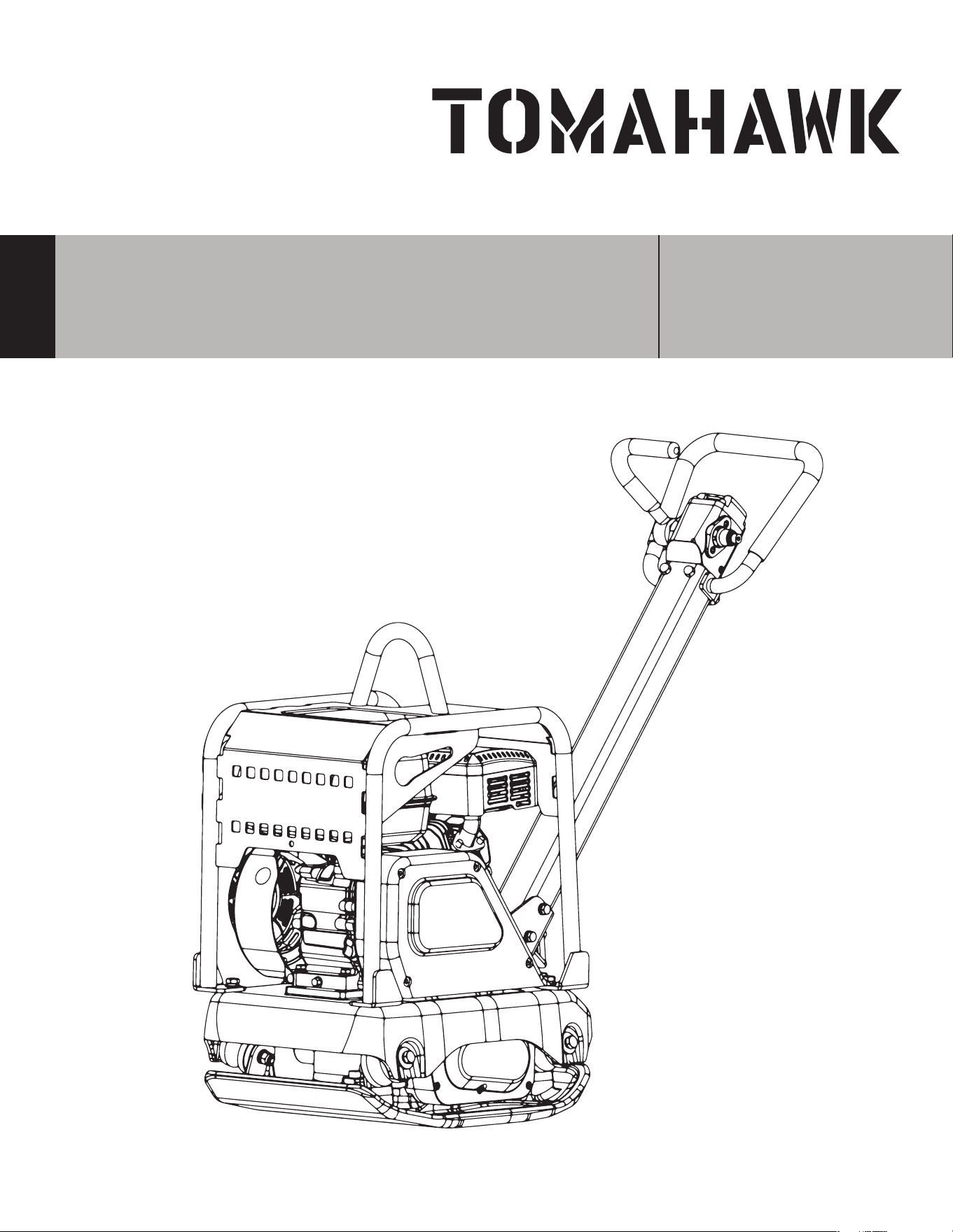
Operation Manual
REVERSE HYDRAULIC
PLATE COMPACTOR
MODEL NUMBER: TPC100H

2
Table of Contents
1. SAFETY INFORMATION
1.1 Laws Pertaining to Spark Arresters
1.2 Operating Safety
1.3 Safety While Using Combustion Engines
1.4 Service Safety
2. PRODUCT DETAILS
2.1 Compactor Description
2.2 Specifications
2.3 Compactor Components
3. OPERATION
3.1 Recommended Fuel
3.2 Before Starting
3.3 Starting the Engine
3.4 Stopping the Engine
3.5 Application
3.6 Operation
4. MAINTENANCE
4.1 Periodic Maintenance
4.2 Cleaning the Plate
4.5 Spark Plug
4.6 Engine Oil
4.7 Air Filter
4.8 Cleaning Sediment Cup
4.9 Carburetor Adjustment
4.10 Hyrdaulic Oil
5. TROUBLESHOOTING
6. STORAGE
7. EQUIPMENT WARRANTY
8. COMPACTION TIPS
4
5
5
6
6
7
7
7
8
11
11
11
11
12
12
12
13
13
13
14
14
15
15
16
17
18
18
19
20

3
Register Your Equipment
Thank you for purchasing TOMAHAWK equipment! Your product is covered by the
TOMAHAWK Warranty policy, but in order to activate your warranty, we need you to register
your product. In addition to activating your equipment warranty, product registration will
grant you access to important product updates, streamlined customer service and more.
INCLUDED WITH YOUR REGISTRATION
☑ Equipment Warranty Activation
☑ Product Updates
☑ Streamlined Customer Service
☑ Excusive Discounts and Sales
STEPS TO REGISTER YOUR EQUIPMENT
1. Visit www.tomahawk-power.com
2. Choose “Product Registration” at the bottom of the page
3. Enter your equipment’s serial number to get started
4. Provide all required information
5. Submit Registration
Equipment Resources
Tomahawk Customer Service doesn’t stop at checkout. We understand to keep a job-site
running smoothly - the proper equipment, spare parts, instruction manuals, and more are
needed at the drop of a hat. Visit www.tomahawk-power.com to gain access to the incredible
resources below.
How To Video Library
More of a visual person? Visit our Video Library for equipment
assembly instructions, troubleshooting tips, and more!
Found on each product listing or the Service Videos Page
Manual and Assembly Guide Library
Visit our Manual Library if you are looking for a lost
operations manual or a particular spare part?
Found on each product listing or the Tomahawk Manuals Page
Service Requests
In need of a quick fix or a service center referral? Submit a
Service Request and a Tomahawk Technician will respond
shortly to get you the help you need.
Choose “Service Request” at the bottom of www.tomahawk-power.com

4
This manual provides information and procedures to safely operate and maintain this
equipment. For your own safety and protection from injury, carefully read, understand and
observe the safety instructions described in this manual.
Keep this manual or a copy of it with the equipment. If you lose this manual or need an
additional copy, please contact Tomahawk Power LLC or visit www.tomahawk-power.com
This equipment is built with user safety in mind; however, it can present hazards if
improperly operated and serviced. Follow operating instructions carefully. If you have
questions about operating or servicing this equipment, contact Tomahawk Power.
The information contained in this manual is based on equipment’s production at the time of
publication. Tomahawk Power reserves the right to change any portion of this information
without notice.
No part of this publication may be reproduced in any form or by any means, electronic or
mechanical, including photocopying, without express written permission from
Tomahawk Power.
Any type of reproduction or distribution not authorized by Tomahawk Power represents an
infringement of valid copyrights and will be prosecuted. We expressly reserve the right to
make technical modifications, even without due notice, which aim at improving our
machines or their safety standards.
1. SAFETY INFORMATION
This manual contains DANGER, WARNING, CAUTION, and NOTE callouts which must be
followed to reduce the possibility of personal injury, damage to the equipment, or improp-
er service.
This is the safety alert symbol. It is used to alert you to potential personal injury
hazards. Obey all safety messages that follow this symbol to avoid possible injury
or death.
DANGER indicates an imminently hazardous situation which, if not avoided, will
result in death or serious injury.
WARNING indicates a potentially hazardous situation which, if not avoided, could
result in death or serious injury.
CAUTION indicates a potentially hazardous situation which, if not avoided, may
result in minor or moderate injury.
DANGER
WARNING
CAUTION

5
CAUTION: Used without the safety alert symbol, CAUTION indicates a potentially
hazardous situation which, if not avoided, may result in property damage.
1.1 Laws Pertaining to Spark Arresters
Notice: State Health Safety Codes and Public Resources Codes specify that in certain
locations spark arresters be used on internal combustion engines that use hydrocarbon
fuels. A spark arrester is a device designed to prevent accidental discharge of sparks or
flames from the engine exhaust. Spark arresters are qualified and rated by the United
States Forest Service for this purpose.
In order to comply with local laws regarding spark arresters, consult the engine distributor
or the local Health and Safety Administrator.
1.2 Operating Safety
Familiarity and proper training are required for the safe operation of equipment!
Equipment operated improperly or by untrained personnel can be dangerous! Read
the operating instructions contained in both this manual and the engine manual and
familiarize yourself with the location and proper use of all controls. Inexperienced
operators should receive instruction from someone familiar with the equipment before
being allowed to operate the machine.
1.2.1 NEVER allow anyone to operate this equipment without proper training. People
operating this equipment must be familiar with the risks and hazards associated with it.
1.2.2 NEVER touch the engine or muler while the engine is on or immediately aer it has
been turned o. These areas get hot and may cause burns.
1.2.3 NEVER use accessories or attachments that are not recommended by Tomahawk
Power. Damage to equipment and injury to the user may result.
1.2.4 NEVER leave machine running unattended.
1.2.5 ALWAYS be sure operator is familiar with proper safety precautions and operation
techniques before using machine.
1.2.6 ALWAYS wear approved safety goggles or safety glasses with side shields, or when
needed, a face shield. Use a dust mask in dusty work conditions. Also use non-skid safety
shoes, hardhat, gloves, dust collection systems, and hearing protection when appropriate.
This applies to all persons in the work area.
1.2.7 ALWAYS close fuel valve on engines equipped with one when machine is not being
operated.
1.2.8 ALWAYS store equipment properly when it is not being used. Equipment should be
stored in a clean, dry location out of the reach of children.
WARNING

6
1.2.9 ALWAYS operate machine with all safety devices and guards in place and in working
order. DO NOT modify or remove safety devices. DO NOT operate machine if any safety
devices or guards are missing or inoperative.
1.2.10 ALWAYS read, understand, and follow procedures in Operator's Manual before
attempting to operate equipment.
1.3 Safety While Using Combustion Engines
Internal combustion engines present special hazards during operation and fueling!
Read and follow warning instructions in engine owner's manual and safety guidelines
below. Failure to follow warnings and DANGER safety guidelines could result in severe
injury or death.
1.3.1 DO NOT run machine indoors or in an enclosed area such as a deep trenches unless
there is adequate ventilation, through such items as exhaust fans or hoses are provided.
Gasoline exhaust from the engine contains poisonous carbon monoxide gas; exposure to
carbon monoxide can cause loss of consciousness and may lead to death.
1.3.2 DO NOT smoke while operating machine.
1.3.3 DO NOT smoke when refueling engine.
1.3.4 DO NOT refuel hot or running engine.
1.3.5 DO NOT refuel engine near open flame.
1.3.6 DO NOT spill fuel when refueling engine.
1.3.7 DO NOT run engine near open flames.
1.3.8 ALWAYS refill fuel tank in well-ventilated area.
1.3.9 ALWAYS replace fuel tank cap aer refueling.
1.3.10 ALWAYS check fuel lines and fuel tank for leaks and cracks before starting engine.
1.3.11 DO NOT run machine if fuel leaks are present or fuel lines are loose.
1.4 Service Safety
Poorly maintained equipment can become a safety hazard! In order for the
equipment to operate safely and properly over a long period of time, periodic
maintenance and occasional repairs are necessary.
1.4.1 DO NOT attempt to clean or service machine while it is running. Rotating parts can
cause severe injury.
1.4.2 DO NOT crank a flooded engine with the spark plug removed on gasoline-powered
engines. Fuel trapped in the cylinder will squirt out the spark plug opening.
DANGER
WARNING

7
1.4.3 DO NOT test for spark on gasoline-powered engines, if engine is flooded or the smell of
gasoline is present. A stray spark could ignite fumes.
1.4.4 DO NOT use gasoline or other types of fuels or flammable solvents to clean parts,
especially in enclosed areas. Fumes from fuels and solvents can become explosive.
1.4.5 ALWAYS keep area around muler free of debris such as leaves, paper, cartons, etc. A
hot muler could ignite them, starting a fire.
1.4.6 ALWAYS replace worn or damaged components with spare parts designed and
recommended by Tomahawk Power.
1.4.7 ALWAYS disconnect spark plug on machines equipped with gasoline engines, before
servicing, to avoid accidental start-up.
1.4.8 ALWAYS keep machine clean and labels legible. Replace all missing and hard-to-read
labels. Labels provide important operating instructions and warn of dangers and hazards.
1.4.9 ALWAYS check for damaged parts before each use. Carefully check that the equipment
will operate properly and perform its intended function. Replace damaged or worn parts
immediately. Never operate the screed with a damaged part.
1.4.10 ALWAYS inspect the machine prior to placing in storage and before re-use. Store the
machine in a dry, secure place out of the reach of children when not in use.
1.4.11 ALWAYS use only accessories that are recommended by the manufacturer for use
with the machine. Accessories that may be suitable for one machine may create a risk of
injury when used with the machine.
2. PRODUCT DETAILS
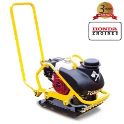
2.1 Compactor Description
Powered by a 5.5HP Honda Engine, the TPC100H reverse plate compactor is perfect for
retaining walls, asphalt, and more. Designed with a 18.8 in. x 13.7 in. plate. Operating at 16.5
Kn, the TPC100H compacts cohesive and granular soils up to 16.3 inches!
2.2 Specifications
Model TPC100H
Engine Honda GX160
Horsepower 5.5 HP
Travel Speed 64 ft per min
Noise Level 82 dB
Centrifugal Force 16.5 Kn
Frequency 6000 vpm
Compaction Depth 16.3 in.
Plate Size (LxW) 18.8 x 13.7 in
Weight
Oil Type
Hydraulic Oil Type
210 lbs
SAE 10W-30
Shell Tellus Oil #32 or Equivalent

8
2.3 Compactor Components

9
1. Hydraulic Pump (Oil Reservoir): Regulates hydraulic oil flow produced by the direction
of the control lever.
2. Liing Bale: When liing of the compactor is required either by forkli, crane, etc., tie
rope or chain around this liing spot.
3. Vibrating Plate: A flat, open plate made of durable cast iron construction used in the
compacting of soil.
4. Front Cover: Open to access engine and other components.
5. Engine: This plate compactor uses a 4-sroke series gasoline engine. Refer to the
owner’s manual for engine information.
6. Direction Control Lever: Push the lever forward to move compactor in a forward direction.
Pull the lever backwards to move compactor in backwards direction. Placing the lever in the
middle (midway) will cause the compactor not to move (neutral).
7. Throttle Lever: Controls speed of the plate compactor. Place straight vertically to start,
push fully counterclockwise for full throttle and fully clockwise to stop plate compactor.
8. Handle Bar: When operating the compactor, this handle is to be in the downward position.
When the compactor is to be stored, move the handle bar to the upright position.
9. Vibration Case Oil Filter: Used to add oil to the vibration case.
10. Breather Plug: Allow pressure to escape to the air in the form of a gas from heat.
11. Hand Grip: When operating the compactor use this hand grip to maneuver the compactor.
12. Rubber Cover: Li this rubber cover to gain access to the fuel tank.
10
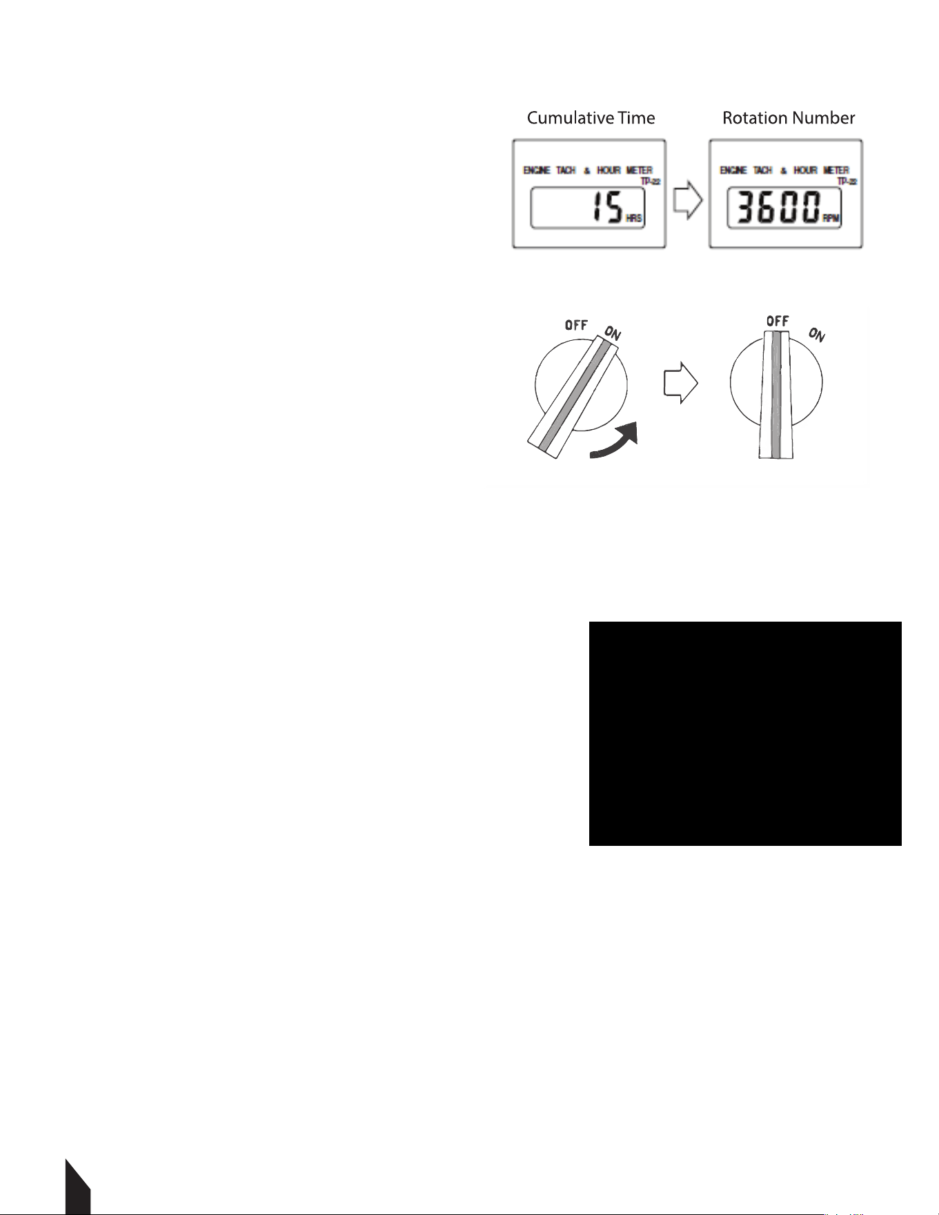
13. Hour/Tachometer: Displays the cumulative
time that the machine has been in use. During
operation it displays the rpm reading.
14. Engine ON-OFF Switch: Used to turn the
engine on or o.
15. Handle Bar Height Adjuster: Adjusts the handle bar to the desired height by loosening the
wing nut and turning the grip clockwise to raise the handle bar and counterclockwise to lower
the handle bar.
2.4 Understanding The Control Lever
The direction control lever allows the machine to be
moved either backward or forward. When the direction
control lever is pushed forward, the machine moves forward.
When pulled backward, the machine moves backward.

11
- Oil level and fuel levels
- V-Belt tension
- Handles / Control Lever
- Tightness of external fasteners
- Condition of fuel lines
- Condition of air filter
A
B
D
C
3. OPERATION
3.1 Recommended Fuel
The engine requires regular grade unleaded gasoline, 87 octane or higher. Use only fresh,
clean gasoline. Gasoline containing water or dirt will damage fuel system. Consult engine
owner's manual for complete fuel specifications.
3.2 Before Starting
Read and understand safety and operating instructions at beginning of this manual.
3.2.2 Check:
3.3 Starting the Engine
3.3.1 Open fuel valve by moving lever to the “ON” position (A).
NOTE: If engine is cold, move choke lever to close position.
If engine is hot, set choke to open position (B).
3.3.2 Move the throttle lever to the idle position (C).
3.3.3 Pull starter rope (D).
NOTE: If the oil level in the engine is low, the engine
will not start. If this happens, add oil to engine.
Some engines are equipped with an oil alert light
that will come on while pulling the starter rope.
3.3.4 Open choke as engine warms (B).
3.3.5 Open throttle fully to operate.

12
3.4 Stopping the Engine
3.4.1 Reduce engine RPM to idle by moving throttle completely to right (C).
3.4.2 Turn the red engine switch to "OFF".
3.4.3 Close fuel valve by moving lever to the le (A).
3.5 Application
This plate is designed for compacting patchwork on asphalt, cohesive soils, granular soils,
sticky soils (clay or slit), gravel, sand, or mixed soils. It is designed to specifically maeuver
narrow, cramped spaces, the TPC100H compacts cohesive and granualr soils up to 15
inches, while its self-cleaning, open base plate minimizes rock and dirt build up.
3.6 Operation
3.6.1 Run engine at full throttle and allow plate to pull itself along at its normal speed. When
operating on an incline it may be necessary to assist plate by pushing it forward slightly.
Depending on the material being compacted, three or four passes are recommended to
achieve the best compaction.
While a certain amount of moisture in the soil is necessary, excessive moisture may cause
soil particles to stick together and prevent good compaction. If soil is extremely wet, allow it
to dry somewhat before compacting.
3.6.2 If soil is so dry as to create dust clouds while operating plate, some moisture should be
added to the ground material to improve compaction. This will also reduce service to the air
filter.
When using the plate on paving stones, attach a pad to the bottom of the plate to prevent
chipping or grinding surface of the stones. A special polyurethane pad designed for this
purpose is available as an optional accessory.
CAUTION
DO NOT operate plate on concrete or on extremely hard, dry, compacted
surfaces. The plate will jump rather than vibrate and could damage both
plate and engine.
4. MAINTENANCE
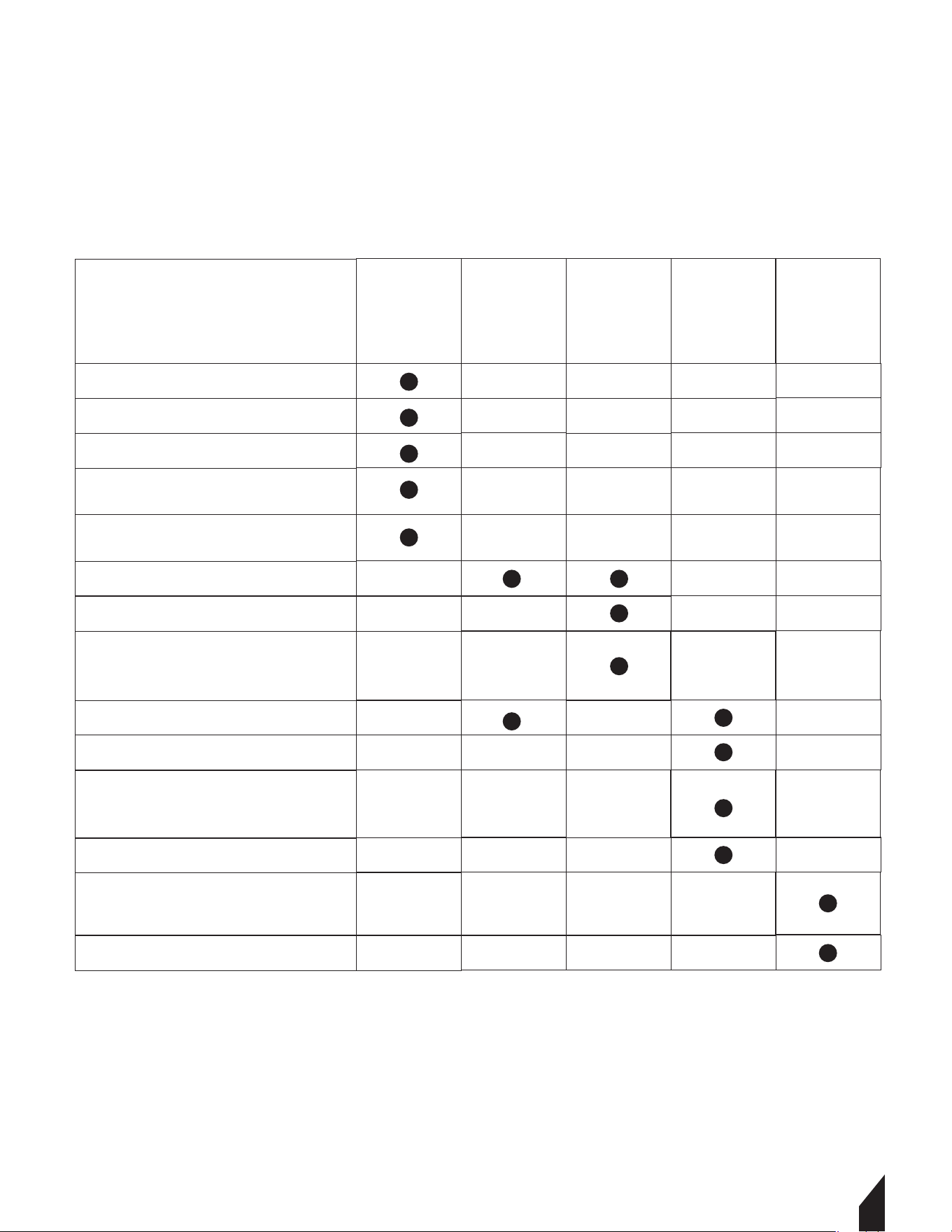
4.1 Periodic Maintenance
The chart below lists basic engine maintenance. Refer to engine manufacturer's Operation
Manual for additional information on engine maintenance.
4.2 Cleaning the Plate
Clean the plate aer use to remove dirt, stones, and mud caught under the engine console.
If plate is being used in a dusty area, check engine cylinder cooling fins for heavy dirt
accumulation. Keep engine cylinder fins clean to prevent engine from overheating.
Daily
before
starting
Check fuel level.
Check engine oil level.
Inspect fuel lines.
Check and adjust drive belt.
Clean air cleaner elements.
Inspect shockmounts for
damage.
Change engine oil.
Clean engine cooling fins.
Clean sediment cup / fuel
filter.
Check and clean spark plug.
Check and adjust valve
clearance.
Change exciter oil.
Inspect air filter. Replace
as needed.
Check and tighten external
hardware.
Aer
first 20
hours
Every 2
weeks or
50 hours
Every
month or
100 hours
Every
year or
300 hours
13
14
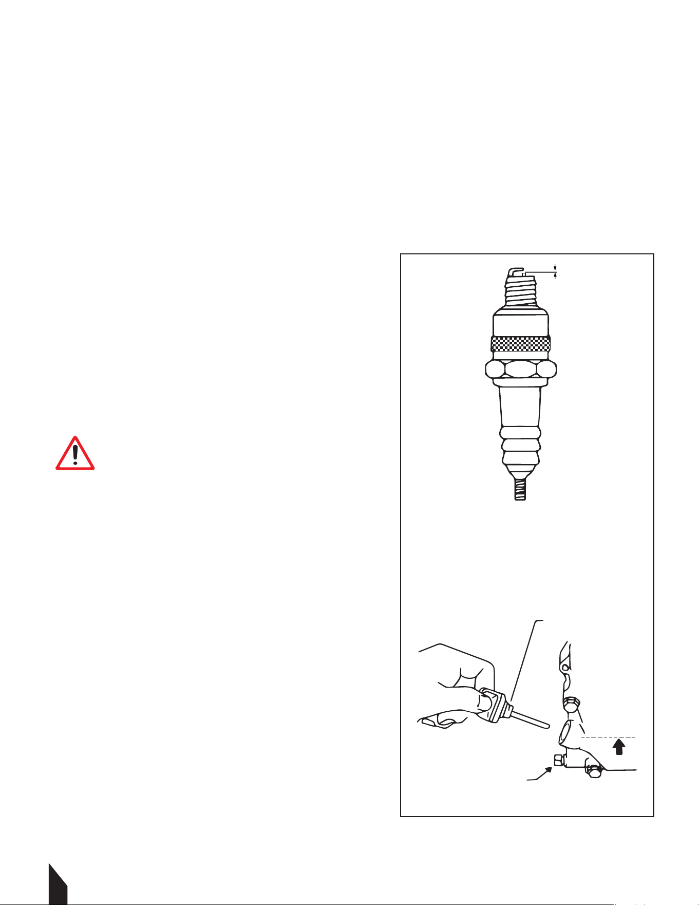
4.5 Spark Plug (Fig. 5)
Clean or replace the spark plug as needed to ensure proper operation. Refer to the engine
owner's manual.
The muler becomes very hot during operation and remains hot for a while aer stopping
the engine. Do not touch the muler while it is hot.
NOTE: Refer to the Technical Data for the
recommended spark plug type and the electrode gap
setting (page 6).
4.5.1 Remove spark plug and inspect it.
4.5.2 Replace plug if the insulator is cracked or
chipped.
4.5.3 Clean spark plug electrodes with a wire brush.
4.5.4 Set the electrode gap (a).
4.5.5 Tighten spark plug securely.
4.6 Engine Oil (Fig. 6)
4.6.1 Drain oil while the engine is still warm.
4.6.2 Remove the oil fill plug (a) and drain plug (b) to
drain oil.
4.6.3 Install drain plug.
4.6.3 Fill the engine crankcase through the oil
opening (b), to the upper mark on the dipstick (c).
Do not thread in the dipstick to check the level. See
Technical Data for oil quantity and type (page 6).
4.6.4 When the crankcase is full, reinstall the
dipstick.
NOTE: In the interests of environmental protection,
place a plastic sheet and a container under the
machine to collect any liquid which drains o.
Dispose of this liquid in accordance with
environmental protection legislation.
a
Fig. 5
Fig. 6
a
b
c
CAUTION
A loose spark plug can become very hot and
may cause engine damage.
15
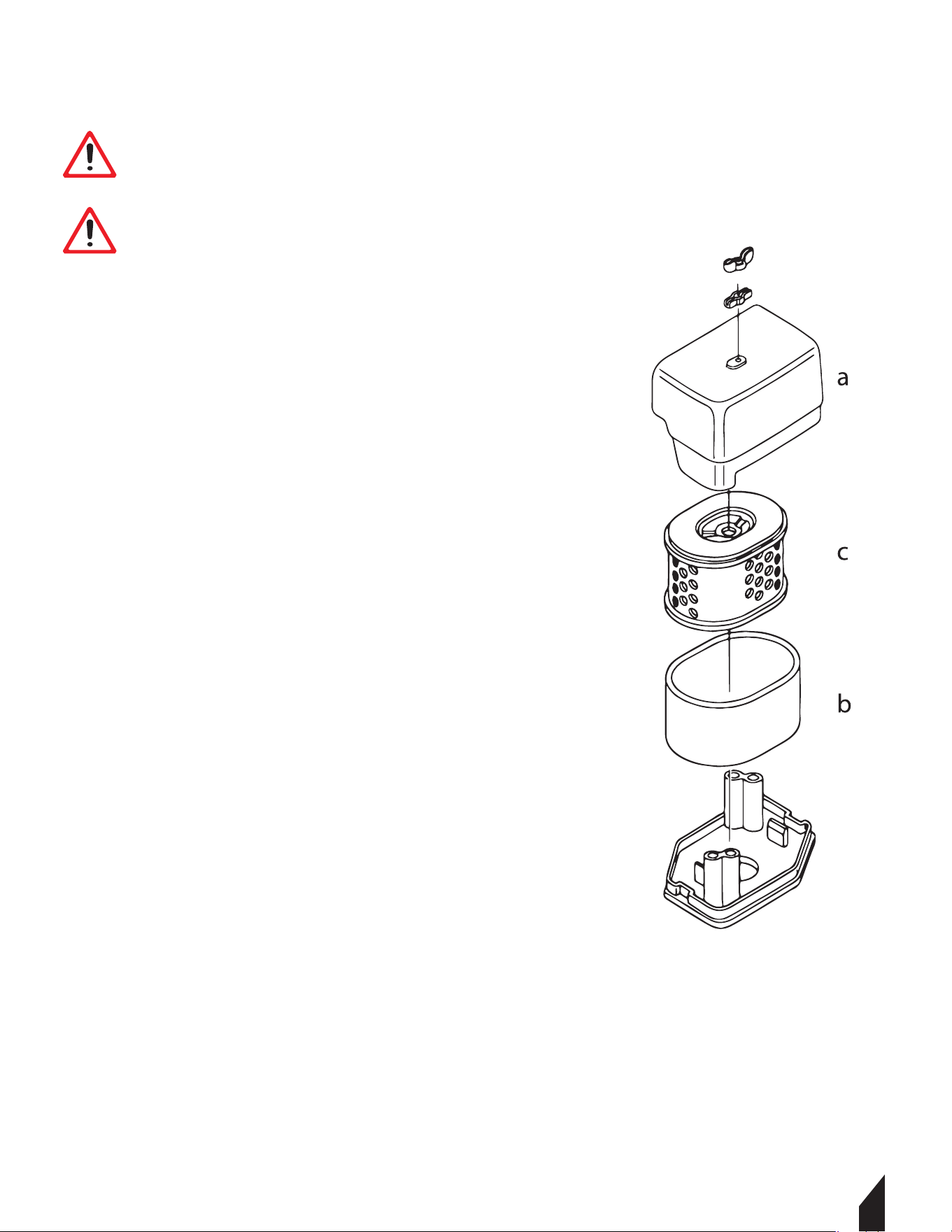
4.7 Air Filter (Fig. 7)
The engine is equipped with a dual element air cleaner.
Under normal operating conditions, elements should be
cleaned once every week. Under severe, dry and dusty
conditions, the elements should be maintained daily.
Replace an element when saturated with dirt that cannot
be removed.
4.7.1 Remove the air cleaner cover (a). Remove both
elements and inspect them for holes or tears. Replace
damaged elements.
4.7.2 Wash the foam element (b) in a solution of mild
detergent and warm water. Rinse it thoroughly in clean
water. Allow the element to dry thoroughly.
4.7.3 Tap the paper element (c) lightly to remove excess
dirt or blow compressed air through the filter from the
inside out. Replace the paper element if it appears heavily
soiled.
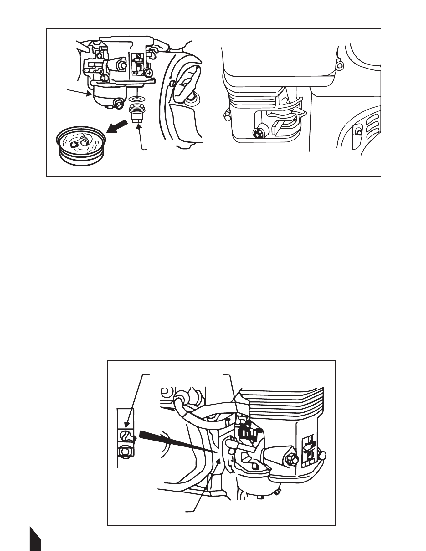
4.8 Cleaning Sediment Cup (Fig. 8)
4.8.1 Turn fuel valve o.
4.8.2 Remove sediment cup (a) and O-ring (b).
4.8.3 Wash both thoroughly in a nonflammable solvent. Dry and reinstall them.
4.8.4 Turn fuel valve on and check for leaks.
WARNING
NEVER use gasoline or other types of low flash point solvents for cleaning the
air filter. A fire or explosion could result.
CAUTION
NEVER run engine without air filter: Severe engine damage will occur and a fire
or explosion could result.
16
4.9 Carburetor Adjustment (Fig. 9)
4.9.1 Start the engine and allow it to warm up to operating temperature.
4.9.2 Set the pilot screw (a) 2 turns out. See Note.
4.9.3 With the engine idling, turn the pilot screw (a) in or out to the setting that produces
the highest rpm.
4.9.4 Aer the pilot screw is adjusted, turn the throttle stop screw (b) to obtain the stan-
dard idle speed. See Technical Data.
NOTE: On some engines the pilot screw is fitted with a limiter cap (c) to prevent excessive
enrichment of the air-fuel mixture in order to comply with emission regulations. The mix-
ture is set at the factory and no adjustment should be necessary. Do not attempt to remove
the limiter cap. The limiter cap cannot be removed without breaking the pilot screw.
Fig. 8
a
b
Fig. 9
a
c b

17
CAUTION
DO NOT exceed OIL LEVEL of hydraulic oil. If the level is higher, oil will
burst out from the breather plug.
4.10 Hydraulic Oil
4.10.1 Start With the handle in vertical position, remove the plug cap from the hydraulic pump.
4.10.2 Remove the breather plug with a 24 mm wrench at the top of the hydraulic pump.
4.10.3 Remove the hydraulic hose connected to the cylinder on the vibrator side.
4.10.4 Drain the hydraulic oil from the pump.
4.10.5 Aer the oil is drained, attach the hydraulic hose again to the cylinder on the vibrator side.
4.10.6 Pour hydraulic oil (330 cc) to the hydraulic pump breather plug attachment hole .
4.10.7 Remove the air releasing plug of vibrator cylinder. Oil will then come out from the air
releasing plug. Aer air bubbles stop coming out, reattach the plug. Tighten securely.
4.10.8 In case the air bleeding is insuicient, repeat step 7.
4.10.9 Attach the hydraulic pump breather plug and put on the plug cap. Aer making sure the
hydraulic oil in the pump is at OIL LEVEL, attach the breather plug.
17

1718
5. TROUBLESHOOTING
6. STORAGE
If the plate compactor is being stored for more than 30 days:
6.1 Storage Tips
6.1.1 Remove loose stones and dirt from plate.
6.1.2 Clean engine cylinder cooling fins.
6.1.3 Clean or replace air filter.
6.1.4 Change exciter oil.
6.1.5 Change engine oil and follow stroage procedures described in the engine manual.
6.1.6 Cover plate and engine and store in a clean, dry area.
Problem / Symptom
-Plate does not develop
full speed.
-Poor compaction.
-Engine running, no
vibration.
• Engine throttle control is not completely open.
• Throttle control is not adjusted correctly.
• Ground is too wet, plate sticking. Allow soil to dry
before compacting.
• Drive belt is loose or worn, slipping on pulleys. Adjust or
replace belt. Check that the engine mounting bolts are
tight.
• Exciter bearings binding. Check condition and level of
oil in exciter. Add or change oil.
• Air filter is clogged with dust, reducing engine
performance. Clean or replace air filter.
• Engine speed is too low. Check the engine speed with
tachometer. Adjust or repair engine to run at correct the
speed. Refer to engine manual.
• Engine throttle is not open.
• Drive belt is loose or broken. Adjust or replace.
• Clutch is damaged. Inspect and replace clutch.
• Engine speed is low. Check engine speed.
• Too much oil in exciter. Adjust oil to the correct level.
-Plate jumps or
compacts unevenly.
• Ground surface is too hard.
• Shockmounts loose or damaged.
Reason / Remedy

19
7. EQUIPMENT WARRANTY
Your new TOMAHAWK® equipment is warranted to the original purchaser for a period of
one-year (12 months) from the original date of purchase. The TOMAHAWK® warranty is
against defects in design, materials and workmanship.
The following are not covered under the warranty:
7.1.1 Damage caused by abuse, misuse, dropping or other similar damage caused by or as a
result of failure to follow assembly, operation or user maintenance instructions.
7.1.2 Alterations, additions or repairs carried out by persons other than TOMAHAWK® or
their recognized agents.
7.1.3 Transportation or shipment costs to and from TOMAHAWK® or their recognized
agents, for repair or assessment against a warranty claim, on any machine.
7.1.4 Materials and/or labor costs to renew, repair or replace components due to fair
wear and tear.
7.1.5 TOMAHAWK® and/or their recognized agents, directors, employees or insurers will not
be held liable for consequential or other damages, losses or expenses in connection with or
by reason of or the inability to use the machine for any purpose.
7.2 Warranty Claims
Before submitting any warranty claim, you will need to register your
new TOMAHAWK® equipment through www.tomahawk-power.com
or email support@tomahawk-power.com.
Follow the steps on page 3 or scan this QR codes to complete
the equipment registration. Aer registration is complete,
all warranty claims should firstly be directed to TOMAHAWK® through
the online Service Request form found
at www.tomahawk-power.com/pages/service-request.
8. SERVICES CENTERS
Our service centers are equipped to handle your equipment maintenance and repair needs
efficiently. With a network of authorized local service locations , you can find expert
support and genuine parts needed to keep your equipment running smoothly. All locations
are listed on the webpage https://tomahawk-power.com/pages/find-a-service-center.
For Service Call (866) 577- 4476

1720
9. MORE COMPACTION TIPS
9.1 Soil Drop Test: Soil preparedness refers to the “wetness” of the dirt or soil. Soil
needs to be 50% dry and 50% wet, before starting compaction. A simple “hand test” can
determine this. Pick up a handful of soil with your hand and squeeze the dirt. Observe
whether the soil is powdery or if it breaks apart when dropped. If the soil does break apart,
it means that it is too dry. If the soil keeps together in one piece when dropped, it is ready
for compaction.
9.2 Soil Testing: Testing: The function of this step is to measure the density of an aggregate
material to ensure the increase of density when driving out air. At a low moisture content
level, there are more soil particles assembling together. In order to determine if the soil is
compacted properly, there are several methods.
9.2.1 Soil Testing: Test strips are useful to determine the method of compaction and
understand how many passes of your plate compactor are needed to achieve the optimum
compaction. Every layer of compacted soil meets a specific percentage on the proctor
curve. Through soil testing, it is possible to identify optimum moisture. Soil testing mea-
sures the soil density compared to the degree of compaction specifications, as well as the
eect of the moisture.
A common laboratory method called the Proctor Compaction Test can be used to deter-
mine the optimal moisture content for a given soil type. The goal of this method is to
understand the soil’s maximum dry density. A second method of soil testing is known as
the California Test 216 and is used to find the relative compaction of untreated and treated
soils.
Four factors account for optimum compaction including li thickness, pressure, and soil
moisture content. During the compaction process, the soil's moisture adds density and
lubricates soil particles, until there is a maximum dry unit weight without voids in the soil.
The table below explains the dierent outcomes and properties of fill materials.

21
9.3 Compaction Terms
9.3.1 Cohesive soils: Clays and mixes have a particular particle size of less than .003” or
.002” and are typically classified as cohesive soils. This type of soil is primarily used for
retaining pond beds and mound fills. These soils are dense due to the strongly bound mo-
lecular attraction. Cohesive soils and water will not mix easily, but only once the soils are
moist it will feel sticky.
9.3.2 Granular soils: These soils have particle sizes of .003” or greater, like sand. Water
drains easily through the soils particles of granular soils. The larger the particles, the larger
the equipment needed to achieve lower frequencies and higher compaction force. Plate
compactors are typically the best option for compacting granular soils - however, depend-
ing on the vibration frequency and particle size, reversible plate compactors and double
drum rollers may be more appropriate for this type of work.
9.3.3 Mixed soils: Sometimes soils can be a mixture of both types, cohesive and granular.
Thus choosing the appropriate compaction equipment is more diicult. We recommend
testing your equipment to match the best machine to the desired job.

17
22
9.4.4 Static Force: Found in the deadweight of machines, static force applies pressure
downward on soil surfaces. As a result, soil particles compress in the topsoil layer.
9.4.5 Vibratory Force: This force is engine-driven, creating a downward force, in addition
to the machine's static weight. Vibrations compress the soil material closer together to
increase density.
9.4.6 Types of Compaction: There are four types of compaction that can be applied to soils
or asphalt. Each one takes place using one of the two types of the forces explained above
(static or vibratory).
A. Vibration: Periodic motion of particles with rotating weight in opposite directions
from a position of equilibrium.
B. Impact: An action of one object coming into contact with another.
C. Kneading: Force is applied by alternating movement in adjacent positions.
D. Pressure: The process of continuous physical force against solid materials.
Parts Manual
REVERSE HYDRAULIC
PLATE COMPACTOR
MODEL NUMBER: TPC100H
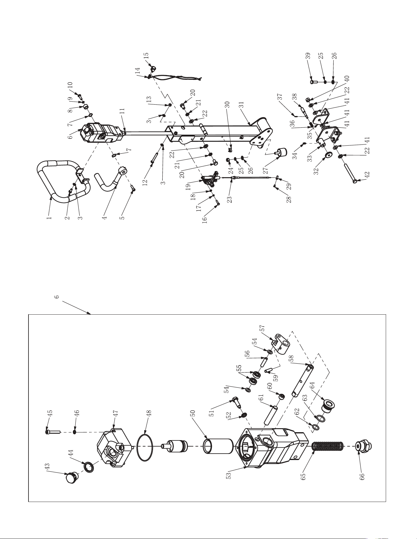
3.
CONTROL

17
No. Description Qty
1 Bolt M8x16 2
2 Washer M8 6
3 Wave Washer 2
4 Handle Grip 1
5 Handle Pump Assy. 1
6 Collar 1
7 Spring Washer M8 1
8 Bolt M8x25 1
9 Allen Screw M8x25 1
10 Travel Lever 1
11 Oil Hose 1
12 Handle Assy. 1
13 Bolt M8 2
14 Switch 1
15 Wire 1
16 Bolt M12 2
17 Washer M12 2
18 Shock Absorber, Handle 1
19 Spring Pin 1
20 Pin 1
21 Bolt M16 1
22 Bolt M10x30 4
23 Spring Washer M10 5
24 Washer M10 5
25 Washer M16 2
26 Wave Washer 4
27 Handle Bracket (R) 1
28 Lock Nut M16 1
29 Handle Bracket (L) 1
30 Spring 1
31 Grease Inlet 1
32 Knob 1
33 Bolt M5 1
34 Lock Nut 1
35 Lock Nut M10 1
36 Wire Clip 2
37 Trottle Wire 1
38 Bolt M6x20 2
39 Spring Washer M6 2
40 Washer M6 2
41 Trottle Lever Assy. 1
42 Lock Nut M8 2
43 Breather Cap 1
44 Sealing M20 1
45 Allen Screw M6 4
46 Spring Washer M6 4
47 Cover, Handle Pump 1
48 O-Ring 1
49 Piston CP 1
50 Bush 1
51 Spacer M8 1
52 Bolt M8 1
53 Nylon Washer 2
54 Bearing 2
55 Pin 1
56 Can 1
57 Stopper 1
58 Pin 1
59 Plug 1
60 Shaft 1
61 Bush 2
62 O-Ring 2
63 O-Ring 2
64 Hose Joint 1
65 Spring 1
66 Body, Handle Pump 1
No.
Description
Qty
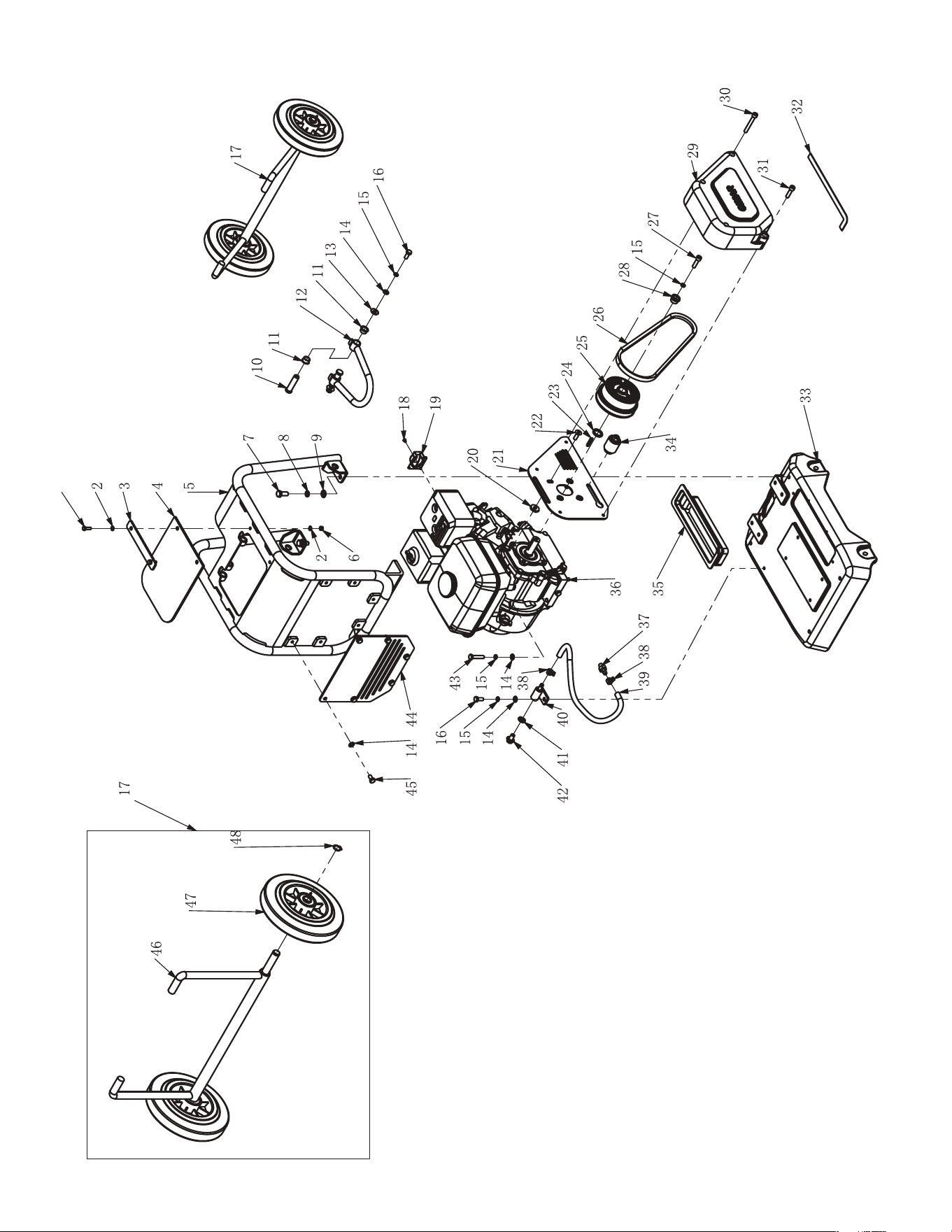
2. ENGINE AND FRAME

No. Description Qty
1 Bolt M6x20 2
2 Washer M6 4
3 Plate, Rubber Cover 1
4 Rubber Cover 1
5 Frame 1
6 Bolt M10x25 4
7 Spring Washer M10 4
8 Washer M10 4
9 Bolt M8x20 3
10 Spring Washer M8 8
11 Washer M8 13
12 Washer M8x22x2 2
13 Bush 4
14 Wheel Kits 1
15 Pin 2
16 Hook 1
17 Engine 1
18 Exhaust Outlet 1
19 Bolt M4 2
20 Lock Nut M6 2
21 Belt Cover Plate 1
22 Spacer 1
23 Key 5x30 1
24 Clutch Assy. 1
25 Belt 1
26 Washer 1
27 Allen Screw M8 1
28 Belt Cover Out 1
29 Allen Screw M8 3
30 Allen Screw M8 1
31 Sponge Sealing 1
32 Engine Base 1
33 Dust Cover 1
34 Allen Screw M6 2
35 R Clamp 1
36 Bolt M6 1
37 Belt Tesioner 1
38 Allen Screw M8 4
39 Washer M8x26x4 4
40 Drain Hose 1
41 Clamp 2
42 Hose Joint 1
43 Plug 1
44 Washer M10x1 1
45 Plug 1
46 Bolt M8x40 4
47 Bolt M8x16 6
48 Front Cover 1
49 Bracket 1
50 Wheel 2
51 Stopper 2
52 Circlip Φ30 1
53 Circlip Φ62 1
54 Bearing 6206 1
55 Clutch Drum 1
56 #N/A 1
61 Bearing 61902 2
61 Washer M10 1
61 Lock Nut M10 1
No.
Description
Qty
5
1
2
3
2
3
1
2
3
4
6
7
8
9
10 2 3
11 12 2 13
14
4
15
16
17
18
19
20
2121
22
26
27
23
24
25
24
20
28
29
30
31
32
33
34
35
20
24
36
37
2121
38
36
24
20
39
40
41
42
43
43
44
45
46
47
50
33
34
35
48
49
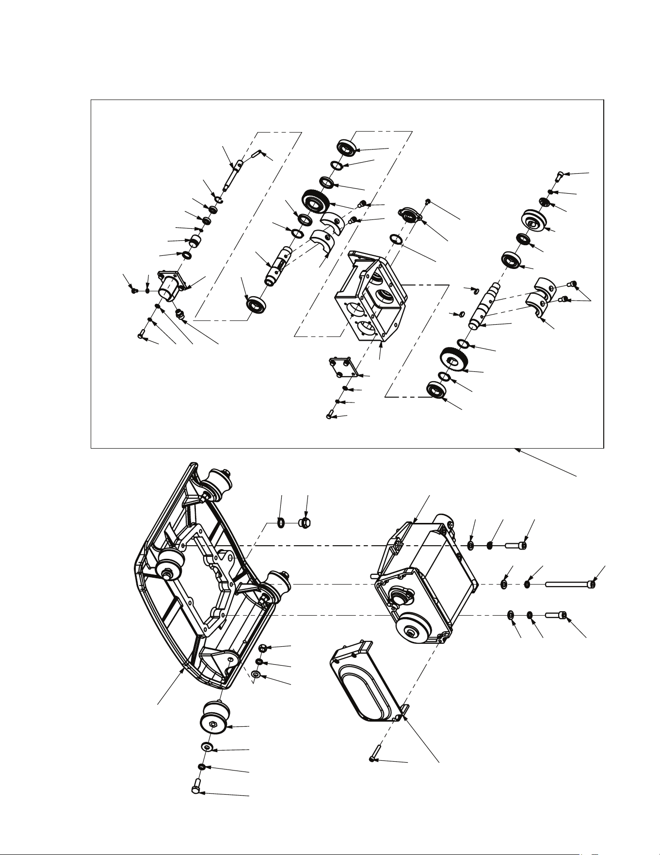
3. VIBERATOR AND PLATE

No. Description Qty
1 Bolt M12 6
2 Spring Washer M12 16
3 Washer M12 12
4 Bolt M12x45 2
5 Viberator Assy. 1
6 Belt Cover Lower 1
7 Allen Screw M6 5
8 Lock Nut M12 4
9 Shock Absorber 4
10 Washer M12 4
11 Bolt M12 4
12 Viberating Plate 1
13 Sealing M16 1
14 Plug M16x1.5x12 1
15 Bolt M8x25 8
16 Spring Washer M8 9
17 Washer M8 8
18 Bearing Cover 1
19 Bearing 4
20 Circlip Φ35 8
21 Gear, Drive 1
22 Rotary Shaft, Drive 1
23 Allen Screw M10 4
24 Eccentric Rotator 4
25 Key 1
26 Bearing 2
27 Shaft, Driven 1
28 Gear, Driven 1
29 Vibrating Case 1
30 Oil Sealing 1
31 Key 1
32 Pulley 1
33 Spacer 1
34 Bolt M8x40 1
35 Bolt M6 2
36 Sealing Cap 1
37 O-Ring Φ43x3.1 1
38 Pin 1
39 Piston Rod 1
40 Stopper 1
41 Bearing 2
42 Spring Washer M10 1
43 Piston 1
44 Oil Sealing 1
45 Cylinder 1
46 Sealing M8 1
47 Blot M8 1
48 Joint 1
No.
Description
Qty

Rammers
8 ft Hydraulic Steer, 35 HP Vanguard,
CVT Clutch, 180 RPM
10 ft Full Hydrostatic, 74 HP Hatz
Diesel
Part#:
TPT24H
TPT36H
TPT46H
Part#: JXPT30H
Part#:
TRT46V
TRT60V
2 ft Edger, Honda GX160, 0-28
o
Blade Pitch
3 ft, Honda GX160/GX270, 0-28
o
Blade Pitch
4 ft, Honda GX270/GX390, 0-28
o
Blade Pitch
HAVE QUESTIONS?
Contact us. We’re here to help!
Email us at [email protected]
Forward Plate Compactors
Reverse Plate Compactors
Part#:
TR68H
JX60H
eJX60H
TVSA-H
eTVSA
Part#:
Part#:
TPC80H
COMPACTION
Power Screeds
Porta-Trowels
Concrete Sprayers
Walk Behind Trowels Ride on Trowels
Early Entry Saws
Part#:
6-16 ft Magnesium Blades
Honda GX35, Adjustable Handles
6-16 ft Magnesium Blades
36V/5 Ah Battery, Adjustable Handles
Part#:
TFS6H
TFS10H
Part#: TCS6.5
6" Blade Diameter, Blade Compatibility,
Honda GX120
10" Blade Diameter, Self Propelled,
Blade Compatibility, Honda GX270/GX390
CONCRETETROWELS
(866) 577-4476
TPC85H
TPC90H
TPC170H
TPC100H
TPC400H
Equipment Guide
3,000 lbs/sq ft, Honda, 21”x17” Plate
3,200 lbs/sq ft, Honda, 23”x17” Plate
3,400 lbs/sq ft, Honda, 22”x20” Plate
3,500 lbs/sq ft, Honda, 19”×14” Plate
7,000 lbs/sq ft, Honda, 28”x20” Plate
11,690 lbs/sq ft, Honda, 32”x22” Plate
Lightweight at 56 lbs
Adjustable 18 ft Extension Bull Float Poles
30" Diameter, 4-Blade Assembly, Honda GX35
Adjustable Blade Pitch from 0-28
o,
Adjustable from 0-450 PSI
Handles 30% + Solids,1.8 HP 2 Stroke Motor, 24"
Brass Wand 0.5 GPM, Fan Nozzle Included,
Spray 15,000 ft
2
in10 Minutes
3,550 lbs/sq ft, Honda GX120
3,350 lbs/sq ft, Honda GX100
3,350 lbs/sq ft, Honda GXE2.0S
Items Listed Includes Combo Blades

3.7 Gal. Tank, Tomahawk 3HP 2 Stroke Engine,
Horizontal Reach: 40ft, Vertical Reach: 25+ft,
50-100 microns, 490 CFM / 220 MPH Air Speed
4 Gal. Tank, 0.7 kW/7.5 Ah, 2hrs @ 1/2 Load,
1hr at Full Load, Spray Reach of 25 - 30ft, 100 -
300 microns, 400 CFM / 150 MPH Air Speed
QUIET INVERTER SERIES
QUIET INVERTER SERIES
Fertilizer SpreadersBackpack Foggers
Part#:
TGDR10
TSCP8
4,000 - 7,000 Watt Series
10,500 - 17,000 Watt Series
Concrete Scarifier
Floor Sweepers
Grinders and Scrapers
Part#:
TSCAR8H
eTSCAR8
Trash Water Pumps
Part#:
TW2H
TW3H
TW4H
3" Pump, Honda GX270, 375 GPM, Elevation:
89ft, Suction: 25ft
2" Pump, Honda GX160, 164 GPM, Elevation:
85ft, Suction: 26ft
4" Pump, Honda GX390, 580 GPM, Elevation:
91ft, Suction: 26ft
QUIET INVERTER SERIES
OUTDOOR POWER GENERATORSFLOORING
www.tomahawk-power.com
(866) 577-4476
ASSEMBLED IN THE
PARTS SOURCED GLOBALLY
USA
TG2000i
TG3000i
TG4500iEFI
2,000 - 4,500 Watt Series
Equipment Guide
10" Disc, 120V, 1/32" Per Pass,
11 AMP, 1.5 HP, 1,725 RPM
8" Blade, 120V, 11 AMP, 3/4 HP,
1,725 RPM, Carpet & Tile Remover
Honda GX160, 350 - 500ft
2
/hr,
OSHA Compliant Vacuum Port,
8" CT Drum Kit, 1/8" Per Pass
2.3HP, 2800 RPM, 350 - 500ft
2
/hr,
OSHA Compliant, 1/8" Per Pass
38" Working Width, Triple Broom
System, 14.5 Gallons
30" Working Width, Battery Powered
Triple Broom System, 13.5 Gallons
4,000w Max / 3,500w Rated, Honda
Engine
5,500w Max / 5,000w Rated, 120/220V
7,000w Max / 6,500w Rated, Honda
Engine
TG4000H
TG5500i
TG7000H
17,000w Max / 14,500w Rated
120/240V, Run Time 14hrs @ 25% Load,
CARB Compliant, GFCI, CO Detector,
Voltage Selector, Electric Start
10,500w Max / 8,500w Rated
120/220V, Run Time 14.5hrs @ 25% Load
TG9000i
TG17000i
92
63
2,200w Max / 2,000w Rated
3,300w Max / 3,000w Rated,
120/220V, 30 AMP Twist Lock
4,500w Max / 3,800w Rated
20A (120V), Electric, Remote
Part#:
eTMD14
TMD14
4 Gal.Tank, Powered by Tomahawk 3HP
2 Stroke Engine, Horizontal Reach of 30 ft,
Displacement of 63.3 cc, MPA of 1.0 - 2.5
5 Gal.Tank, 0.7 kW/7.5 Ah, 36V, Spray Reach
of 25 - 30 ft, Up to 2 hrs at Half load, 1 hr at
Full Load, 2 Hours Charge Time
Part#:
eTGS30
TGS30
Part#:
TOS38
eTOS30
Assorted Blade Choices Assorted Blade Choices
Assorted Brush Choices

Tomahawk understands to keep a job-site running smoothly the proper equipment and
spare parts are needed at the drop of a hat. With same day shipping and faster
delivery times, count on Tomahawk to keep you powered throughout the day! With
long lasting parts and engines, Tomahawk equipment will be the star of your fleet for
years to come. Visit www.tomahawk-power.com to get started today!
Power Your World
FACEBOOK
facebook.com/TomahawkPowerUSA
YOUTUBE
youtube.com/TomahawkPower
INSTAGRAM
@tomahawkpower
TOMAHAWK®, LLC
San Diego, CA
Sales Support
(866) 577-4476
Equipment Support
(866) 577-4476
www.tomahawk-power.com