
Operation and Instruction Manual
Read carefully this operation manual before starting the machine and always keep the instruction -
this way you will secure safe operation, high working output and long durability of the machine.
The manufacturer bears no responsibility for damages arising from mis use or not following the
operation manual.
QUICK START INSTRUCTIONS
1. Unpack Compactor onto a level surface
2. Fuel the Engine (Honda) with 87 Octane + and SAE 10W-30 Oil
3. Open the fuel valve on the Honda engine and move the choke to the choke (cold start) position
4. Make sure the engine switch is in the “ON” position
5. Pull the recoil cord and move the choke to the “RUN” position
6. Move the throttle all the way forward to run the
2

0. QUICK START INSTRUCTIONS
1. SAFETY INFORMATION
1.1 Safety PrecauƟons
1.2 OperaƟng Safety
1.3 Operator Safety while using Internal CombusƟon Engines
1.4 Label LocaƟons
1.5 Safety and OperaƟng Labels
2. OPERATION
2.1 OperaƟng Principle
2.2 Delivery Checks
2.3 Before StarƟng
2.4 To Start
2.5 To Stop
2.6 ApplicaƟon
2.7 OperaƟon
2.8 Max. Admissible InclinaƟon
2.9 Main Parts and Accessories
3. MAINTENANCE
3.1 Periodic Maintenance Schedule
3.2 Exciter Oil
3.3 V-Belt and Clutch
3.3.1 Checking the V-Belt
3.3.2 Replacing the V-Belt
3.3.3 Checking the Clutch
3.4 Air Cleaner
3.5 Spark Plug
3.6 Transport
3.7 TroubleshooƟng
4. TECHNICAL DATA
5. WARRANTY
6. MAINTENANCE RECORDS
TABLE OF CONTENTS
2
4
4
5
7
8
8
10
10
10
10
11
12
12
12
12
13
14
14
14
15
15
15
15
16
16
16
17
19
20
21
3
7. SPARE PARTS MANUAL
23

This manual provides information and procedures to safely operate and maintain this model. For your own
safety and protection from injury, carefully read, understand and observe the safety instructions described in
this manual.
Keep this manual or a copy of it with the machine. If you lose this manual or need an additional copy, please
contact Tomahawk Power LLC or visit www.tomahawk-power.com. This machine is built with user safety in
mind; however, it can present hazards if improperly operated and serviced. Follow operating instructions
carefully. If you have questions about operating or servicing this equipment, please contact Tomahawk
Power or your dealer.
The information contained in this manual is based on machines in production at the time of publication.
Tomahawk Power reserves the right to change any portion of this information without notice. No part of this
publication may be reproduced in any form or by any means, electronic or mechanical, including photocopy-
ing, without express written permission from Tomahawk Power.
Any type of reproduction or distribution not authorized by Tomahawk Power represents an infringement of
valid copyrights and will be prosecuted. We expressly reserve the right to make technical modications, even
without due notice, which aim at improving our machines or their safety standards.
1. SAFETY INFORMATION
1.1 Safety Precautions
This is the safety alert symbol. It is used to alert you to potential personal injury hazards. Obey all
safety messages that follow this symbol to avoid possible injury or death.
DANGER indicates an imminently hazardous situation which, if not avoided, will result in death
or serious injury.
WARNING indicates a potentially hazardous situation which, if not avoided, could result in death
or serious injury.
CAUTION indicates a potentially hazardous situation which, if not avoided, may result in minor
or moderate injury.
CAUTION: Used without the safety alert symbol, CAUTION indicates a potentially hazardous
situation which, if not avoided, may result in property damage.
4

1.2 Operating Safety
-Beware of uneven or slippery work surfaces, as they may cause injury or death.
-Exercise care when working in the vicinity of unprotected holes or excavations.
-NEVER allow any person to operate the machine without adequate instruction.
-NEVER allow any person to operate the machine without adequate instruction.
-ENSURE all operators read, understand and follow the operation instructions.
-Serious injury could result from improper or careless use of the machine.
-Plate compactors are heavy units and should be positioned by two people with appropriate strength, using
the side handles provided with the machine, use proper lifting techniques by lifting with your legs not your
back.
-Plate Compactor may only be used for compaction and asphalt jobs.
-DO NOT operate the machine unless all protective guards are in place.
-ENSURE that the engine switch is in the OFF position and the spark plug ignition lead is disconnected
before removing the guards or making adjustments.
-ENSURE both the machine and the operator are stable by setting up on level terrain so that the machine
will not tip over, slide o or fall while in operation or unattended.
-DO NOT leave the machine in operation (ON), while it is unattended.
-ENSURE that the walls of a trench are stable and will not collapse due to the action of the vibration, prior to
commencing compaction.
-ENSURE that the area to be compacted does not contain any “live” electrical cables, gas, water or communi-
cation services which may be damaged by the action of vibration.
-EXCERCISE CARE when operating unit. Exposure to vibration or repetitive work actions may be harmful to
hands and arms.
-NEVER stand on the machine while it is operating.
-DO NOT increase the governed no-load motor speed above 3,500 r/min. Any increase may result in personal
injury and damage to the machine.
-Be careful and DO NOT come in contact with the muer when the engine is hot, as it can cause severe
burns.
-ENSURE that the repairs to the engine and machine are carried out by competent workers.
5

-DO NOT use the machine near ammable material or in explosive environments.
-Gasoline is extremely ammable and explosive under certain conditions.
-ENSURE that the Gasoline is only stored in an approved storage container.
-DO NOT refuel the engine while it is in operation or hot.
-DO NOT operate or refuel the engine in a conned area without adequate ventilation.
-DO NOT refuel the engine in the vicinity of sparks, a naked ame or smoking.
-DO NOT overll the fuel tank and avoid spilling gasoline when refueling. Spilled gasoline or gasoline vapor
may ignite. If spillage occurs, ensure that the area is dry before starting the motor.
-ENSURE that the fuel tank cap is securely tted after refueling.
-DO NOT operate or refuel a Gasoline motor in a conned area without adequate ventilation.
-Carbon monoxide exhaust gases from engine driven units can cause death in conned spaces.
-EXCESSIVE NOISE can lead to temporary or permanent loss of hearing.
-WEAR an approved hearing protection device to limit noise exposure. As required by Occupational Health
and Safety regulations.
-ALWAYS wear an approved hearing protection when working in a conned work space. Protective goggles
and a dust mask should be worn when working in a dusty environment. Protective clothing and footwear
may also be desirable when working with hot mix bitumen.
-Store the machine properly in a clean, dry place.
6

1.3 Operator Safety while using Internal Combustion Engines
-DO NOT smoke when refueling the engine or operating the machine.
-DO NOT refuel a hot or running engine.
-ALWAYS keep away from all hot or spark-generating objects when refueling the engine.
-ALWAYS rell the fuel tank until the machine has cooled, and in a well-ventilated environment.
-DO NOT spill fuel when refueling the engine.
-ALWAYS take care to use the right type of fuel.
-ALWAYS inspect the fuel leakage regularly.
-NEVER perform any work on the machine while it is running. Before working on it, stop the engine and
disconnect the spark plug wire to prevent accidental starting.
-Avoid prolonged breathing of exhaust gases.
-ALWAYS transport and handle fuel only when contained in approved safety containers
-ALWAYS keep the area around the muer free of debris such as leaves, paper, cartons, etc. A hot muer
could ignite the debris and start a re.
-NEVER run the engine without the air lter.
7
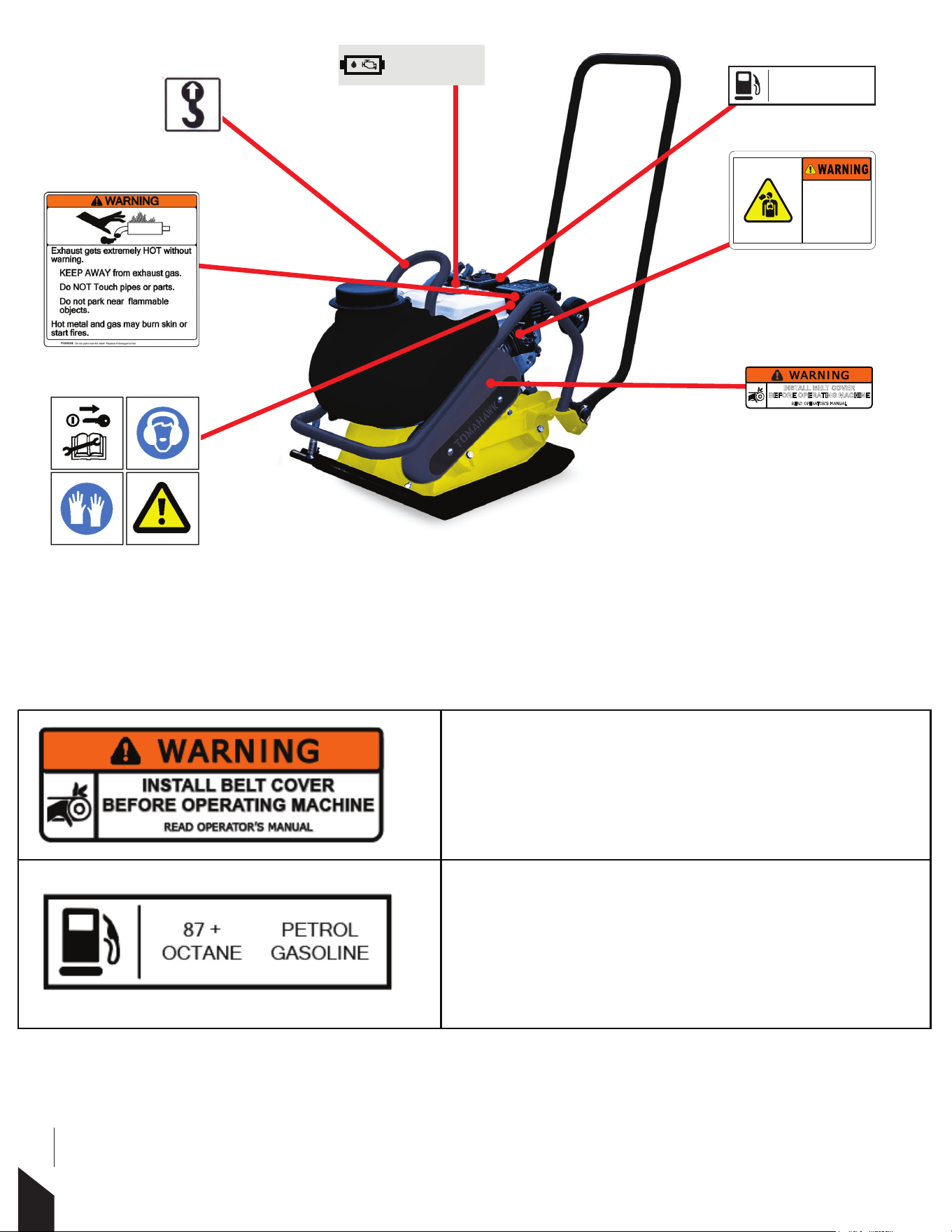
1.4 Label Locations
1.5 Safety and Operating Labels
Tomahawk Power’s machines use international warning labels where needed. These labels are described
next:
WARNING
Injuries to hand may be caused if caught in moving belt.
Alwats replace belt guard.
NOTICE
Only use 87 Octane or higher gasoline.
INSTALL BELT COVER
BEFORE OPERATING MACHINE
READ OPERATOR’S MANUAL
Carbon monoxide (CO) can cause
brain damage or death.
Engine and generator exhaust contains
odorless and colorless carbon monoxide
gas.
Signs of carbon monoxide poisoning
include nausea, headache, dizziness,
drowsiness, and lack of consciousness.
Get fresh air if anyone shows signs of
carbon monoxide poisoning.
87 +
OCTANE
PETROL
GASOLINE
CHECK ENGINE OIL REGULARLY
SAE10W-30
8

WARNING
Engine emits carbon monoxide; operate only in well-
ventilated areas. Read the Operator’s Manual for machine
information. No sparks, ames, or burning objects near
the machine. Shut o the engine before refu-eling. Use
only clean, ltered, unleaded gasoline.
NOTICE
Follow the Maintenance Schedule included in the
Operations Manual to check engine oil regularly.
WARNING
Hot surface!
CAUTION
Lifting point
CAUTION
Read Operations Manual when operating equipment
Use hearing protection when using equipment
Use protective gloves when using equipment
9

2. OPERATION
2.1 Operating Principle
The following instructions were compiled to provide you information on how to obtain long and trouble-free
use of the unit. Periodic maintenance of this unit is essential. Read the manual in its entirety and follow the
instructions carefully. Failure to do so may injure yourself or a bystander.
2.2 Delivery Checks
Immediately on taking delivery of your new equipment and before putting it into service.
-Read the operation manual completely—it could save a great deal of time.
-Read the engine manual supplied.
-Check engine oil level.
-Check fuel levels.
Recommended lubricants are detailed in the Care and Maintenance section.
2.3 Before Starting
The following pre-start-up inspection must be performed before the start of each work session or every four
hours of use, whichever is rst. If any issue is discovered, the compactor must not be used until the issue is
xed.
1. Thoroughly inspect the compactor for signs of damage. Make sure all components are present and secure.
Pay special attention to the belt drive safety guard tted between the engine and the vibrator unit.
2. Check the engine oil and fuel levels and top o as necessary. Add a minimum of unleaded 87 octane gaso-
line and SAE10-30 Oil to the Honda Engine.3. Check for fuel and oil leaks
10
NOTICE: Check the oil level in the engine and exciter. Engine and compactor warranties are VOID if this unit is
run without oil. Note: the Honda engine is built with a low oil sensor switch if the oil level is not adequate the
engine may not start. Before using each time check the oil level.
3. Turn the engine’s ON/OFF switch clockwise to the “ON” position.
4. Set the throttle to the idle position by moving the throttle lever fully to the right. Do not start the engine
on full throttle, as the compactor will vibrate as soon as the engine starts.
5. Taking a rm hold of the control handle with one hand, grasp the recoil starter handle with the other. Pull
the recoil starter until engine resistance is felt, then let starter return.
6. Taking care not to pull the starter’s cord fully out, pull the starter handle briskly.
7. Repeat until the engine res.
8. Once the engine res gradually, set the choke lever to the OFF position by moving it to the right.
9. If the engine fails to re after several attempts, recheck fuel level to make sure they are adequate and then
refer to trouble-shooting guide.
10. To stop the engine, set the throttle to idle and turn the engine ON /OFF switch counter-clockwise to the
“OFF” position.
11. Turn the fuel valve o.
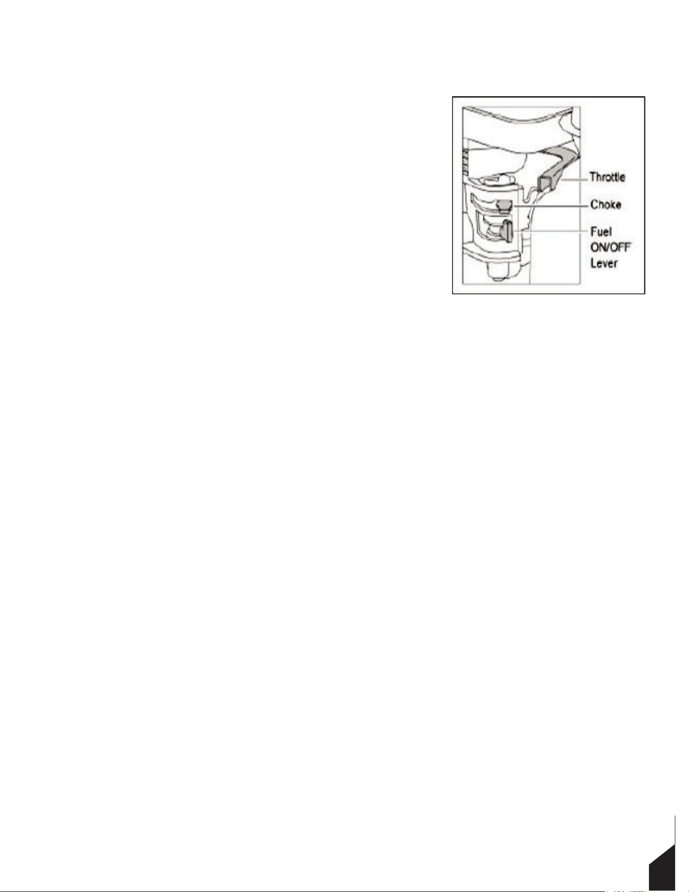
2.4 To Start
1. Open the fuel cap by moving the fuel ON/OFF lever fully to the right.
2. If starting the engine from cold, set the choke to ON by moving the
choke lever fully to the left. If restarting a warm engine, the choke is
usually not required.
However, if the engine has cooled to a degree, partial choke may be
required.
11

2.5 To Stop
1. Move the throttle lever to “Idle” position.
2. Turn the Red On/O switch to “O” position.
3. Close the fuel valve.
2.6 Applications
2.7 Operation
Run the engine at full throttle and allow plate to pull itself along at its normal speed. When operating it may
be necessary to assist plate by pushing it forward slightly. Depending on the material being compacted,
three or four passes are recommended to achieve the best compaction.
The machine is best suited for the compaction of bituminous and granular materials e.g. granular soils such
as silt and clay are best compacted using the impact force produced by a vibrating plate. Where possible the
site should be graded and leveled before compaction.
Correct moisture content in soil also is vital to proper compaction. Water acts as a lubricant to help slide soil
particles together. Too little moisture means inadequate compaction; too much moisture leaves water-lled
voids that weaken the soil’s load-bearing ability. Compaction of dry materials will be facilitated by moisten-
ing with a water hose tted with a sprinkler or simply by using the water tank provided. Excessive watering or
water content will cause the machine to stall.
The optional water tank kit is recommended when the machine is used on bituminous surfaces as the water
lm prevents a build up of material on the underside of the plate.
2.8 Maximum Admissible Inclination
Trench Compaction
Road Maintenance
Brick Paving
Groundwork
Landscaping
Asphalt Compaction
12
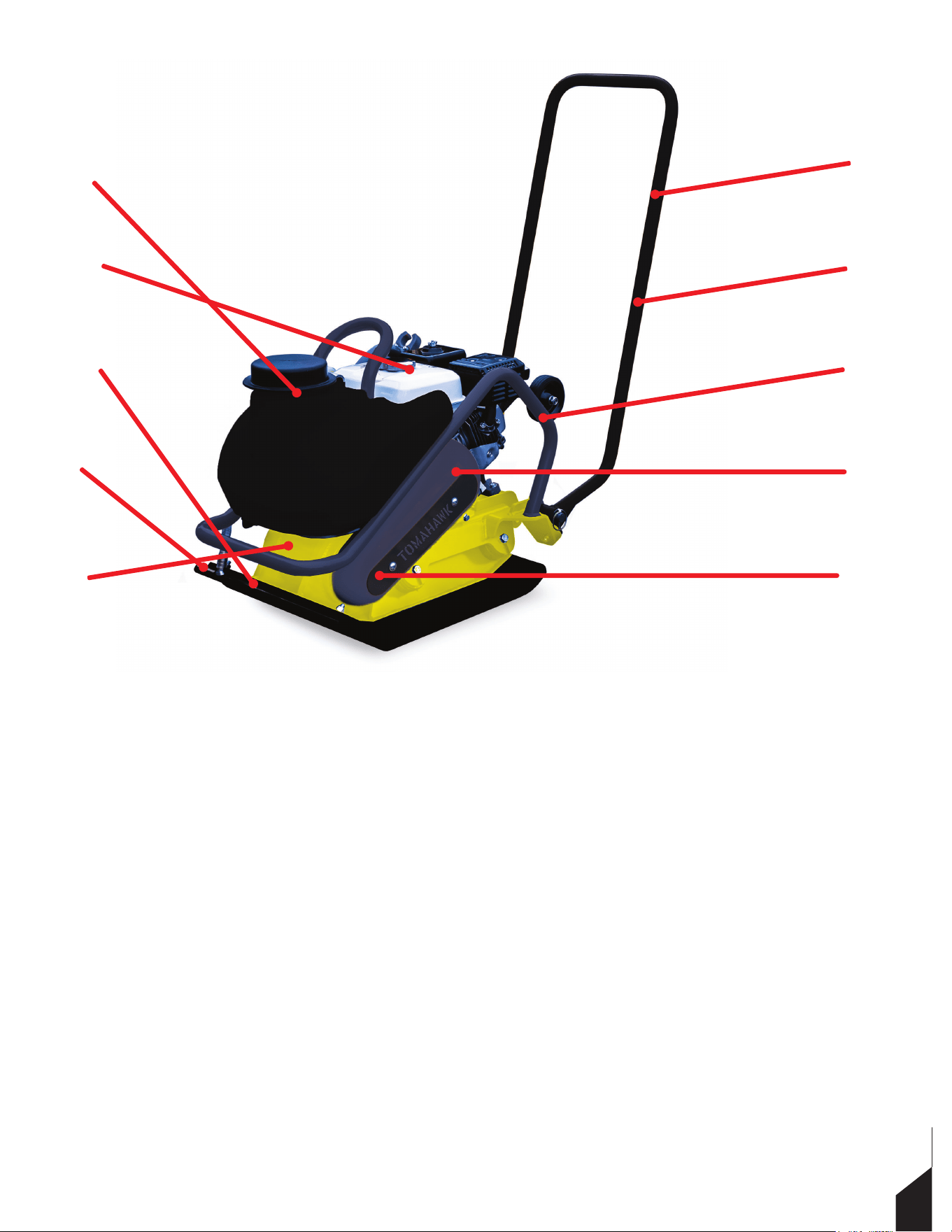
2.9 Main Parts and Accessories
D
I
H
J
G
A
E
C
F
B
F. Belt
G. Clutch
H. Rubber Mat (Optional)
I. Base Plate
J. Exciter
A. Handle
B. Throttle Lever
C. Protective Frame
D. Water Tank (Optional)
E. Belt Cover
13

3. MAINTENANCE
3.1 Periodic Maintenance Schedule
These inspection intervals are meant for operation under normal conditions.
Adjust your inspection intervals based on the number of hours your plate compactor is
in use, and particular working conditions.
3.2 Exciter Oil
When changing the exciter oil, place the exciter on a at, horizontal surface, remove the drain plug located at
the bottom-right of the vibrator, and simply tip the compactor to drain the oil. Note that the oil will drain
more easily while it is hot. DO NOT pour in too much oil.
Daily
After First
20 Hours
Every
50 Hours
Every
100 Hours
Every
200 Hours
Starting Check
Loosened of Lost Screws
Damaged to Parts
Control System Functioning
Exciter Oil Check
Exciter Oil Replacement
V-Belt (Clutch) Check
Leakage of Oil Fuel
Tightness of Fastening Threads
Engine Oil Check and Replenishment
Engine Oil Replenishment
Air Filter Cleaning
14

3.3 V-Belt and Clutch
3.3.1 Checking the V-Belt
After 200 hours of operation, remove the upper belt cover to check
the V-belt tension (Figure 2). Tension is best if the belt bends about
0.4 in when depressed rmly with nger between grooves. Loose
or worn V-belts reduce power transmission eciency, causing weak
compaction, reducing the life of the belt itself.
NEVER attempt to check the V-belt while the engine is running. Severe injury can occur if
your hand is caught between the V-belt and the clutch. Always use safety gloves, while
the engine is ON.
3.3.2 Replacing the V-Belt
Remove the belt covers. Use an o set wrench (13mm) or the like on the vibrator pulley (lower) fastening bolt.
Utilize a waste cloth or the like at midway of V-belt on the le side and while pulling it back strongly, rotate the
o set wrench clockwise so that the V-belt is removed.
3.3.3 Checking the Clutch
Check the clutch simultaneously with V-belt. With the belt removed, check the outer drum of the clutch for
seizure and “V” groove for wear or damage. Clean the “V” groove as necessary. Wear of the lining or shoe
should be checked with running check. If the shoe is worn, power transmission becomes decient and slip-
ping will result.
Whenever the compactor’s vibration becomes weak during normal operation (regardless
of operation hours), check the V-belt and clutch immediately.
15
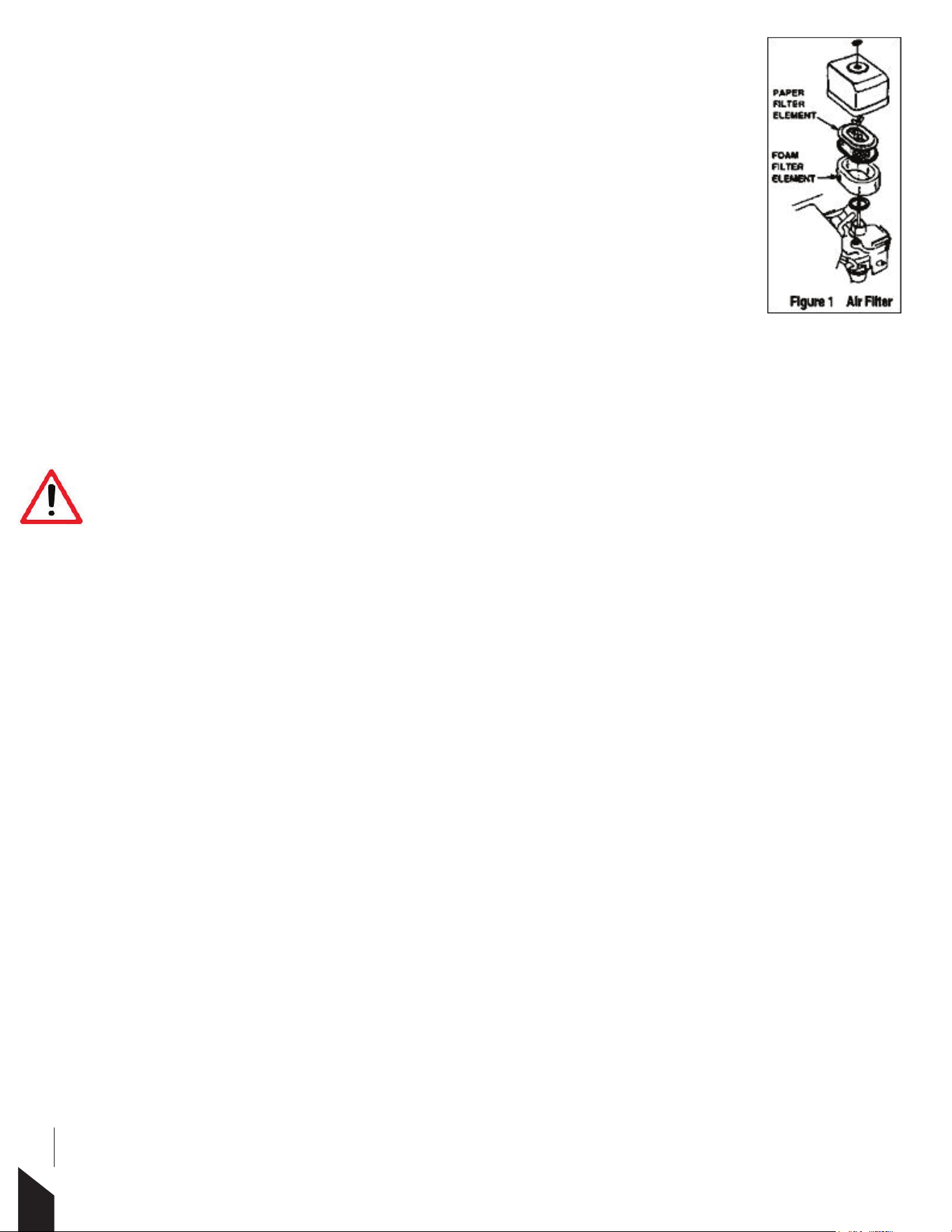
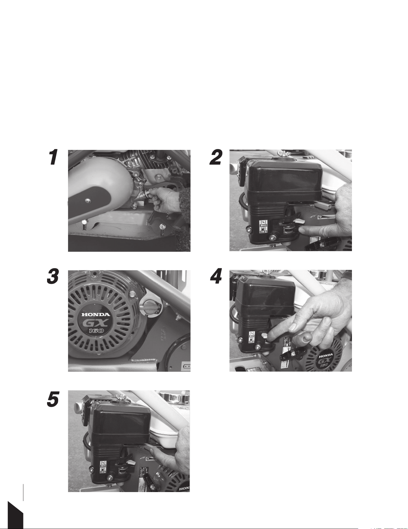
3.4 Air Filter
1. The air lter element should be cleaned as a clogged air lter can cause poor
engine starting, lack of power, and shortened engine life.
2. To clean or replace the air lter, loosen the wing nut on the air lter housing
(Figure 1), remove the cover and take out air lter cartridge. If only cleaning of the
air lter is needed, blow through the air lter cartridge from the inside, with a jet of
dry compressed air, up and down until all dust is removed.
3.5 Spark Plug
Check and clean spark plug’s regularly. A fouled, dirty spark plug may cause hard starting and poor
engine performance. Set the spark plug gap to recommended clearance. Refer to engine manual.
The muer and engine cylinder become very hot during operation and remain hot for a
while after stopping the engine. Allow engine to cool before removing spark plug.
NOTICE: A loose spark plug can become very hot and may cause engine damage.
3.6 Transport Wheels
1. Always shut o engine when transporting the machine.
2. Make sure the lifting device has enough capacity to hold the machine (see nameplate on machine for
weight).
3. Use lifting hook when lifting the machine.
4. The optional wheel kit is used for transporting short distances.
16

3.7 Troubleshooting
3.7.1 Machine Troubleshooting
SYMPTOM POSSIBLE CAUSES SOLUTION
Travel speed too
Engine speed too slow? Set engine speed to correct RPM.
Clutch slips? Check or replace clutch.
low, and the
vibration is weak. V-belt slips? Adjust or replace V-belt.
Excessive oil in vibration?
Drain excess oil and fill to proper level.
Malfunction in vibrator housing?
C
heck eccentric,
g
ears, and counter
weights.
Bearing failure? Replace bearing.
Insufficient engine output? Check engine, compression, etc.
17

3.7.2 Engine Troubleshooting
SYMPTOM
Difficult to start, fuel is
available, but no
SPARK at spark plug.
Difficult to start, fuel is
available, and SPARK is
present at spark plug.
POSSIBLE CAUSES
Spark plug bridging.
Carbon deposit on spark plug.
Short circuit due to deficiency.
Improper spark plug gap.
ON/OFF switch is shorted.
Ignition coil defective.
Improper spark gap, points dirty.
Condenser insulation
worn or short circuiting.
Spark plug wire broken
or short circuiting.
SOLUTION
Check gap, insulation or
replace spark plug.
Clean or replace spark plug.
Check spark plug insulation,
replace if needed.
Set to proper gap.
Check switch wiring, replace switch.
Replace ignition coil.
Set correct spark gap and clean points.
Replace condenser.
Replace defective spark plug wiring.
Difficult to start, fuel is
available, SPARK is
present, and
compression is normal.
Difficult to start, fuel
is available, spark is
present, and
compression is low.
No fuel present
at carburetor.
“Weak in power”
compression is
proper but misfires.
Wrong fuel type.
Water or dust in fuel system?
Air cleaner dirty.
Suction/exhaust valve
stuck or protruded?
Piston ring and/or cylinder worn.
Cylinder head and/or spark
plug not tightened properly.
Head gasket and/or spark
plug gasket damaged.
Fuel not available in fuel tank.
Fuel cock does not open properly.
Fuel filter clogged.
Fuel tank cap breather
hole clogged.
Air in fuel line.
Water in fuel system.
Dirty spark plug.
Ignition coil defective.
Flush fuel system and replace
with correct type of fuel.
Flush fuel system.
Clean or replace air cleaner.
Re-seat valves.
Replace piston rings and or piston.
Torque cylinder head bolts and
spark plug.
Replace head and spark plug gaskets.
Fill with correct type of fuel.
Apply lubricant to loosen fuel
cock lever, replace if necessary.
Replace fuel filter.
Clean or replace fuel tank cap.
Bleed fuel line.
Clean or replace spark plug.
Flush fuel system and replace
with correct type of fuel.
Replace ignition coil.
18
SYMPTOM
“Weak in power”
compression is proper
and does not misfire.
Engine overheats.
Rotational speed
fluctuates.
Recoil starter
malfunction.
POSSIBLE CAUSES
Air filter not clean.
Improper level in carburetor.
Defective spark plug.
Spark plug heat value improper.
Correct type of fuel.
Cooling fins dirty.
Governor adjusted correctly.
Governor spring defective.
Fuel flow restricted.
Recoil mechanism clogged
with dust and dirt.
Spiral spring loose.
SOLUTION
Clean or replace air filter.
Check float adjustment, re-
build carburetor.
Clean or replace spark plug.
Replace with correct type of spark plug.
Replace with correct type of fuel.
Clean cooling fins.
Adjust governor.
Replace governor spring.
Check entire fuel system for leaks or clogs.
Clean recoil assembly with
soap and water.
Replace spiral spring.
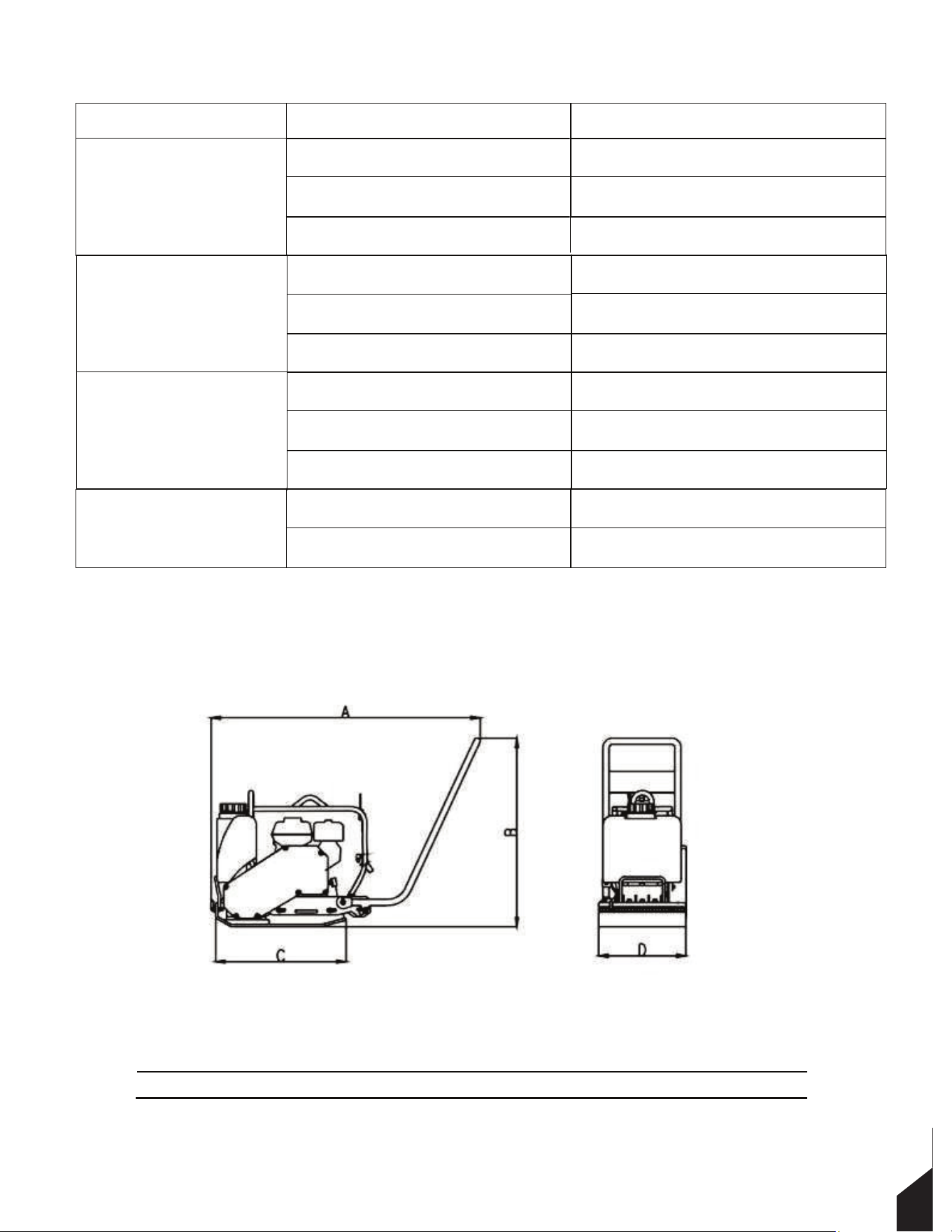
4. TECHNICAL DATA
Size (in):
Model A
B
C D
TPC90H 42.1 38.1 21.9 17.7
19

Sound Specification (According to 2000/14/EC)
Model
Guaranteed sound power level
TPC90H
108dB(A)
V
ibration Specification (According to ISO 2631 and EN 1033) :
Model
TPC90H 5 m/s2
Engine Type
Honda GX160
Power kW (HP)
4.0kW (5.5 HP)
Operating Weight (lb)
187 lbs
Plate Size L x W (in)
22 x 20 in
Centrifugal Force kN
18 kN (4050lbf)
V
ibration Frequency
5,400 vpm (90 Hz)
Travel Speed
78ft /min
Exciter Lubrication
0.25 L, SG15W-40 motor oil
5. WARRANTY
Tomahawk Power products are covered by a Warranty for a period of twelve
(12) months from the date of purchase against defects in material or
workmanship provided that:
-The product concerned has been operated and maintained in
accordance with the operating instructions.
-Has not been damaged by accident, misuse, or abuse.
-Has not been tampered with or repaired by any unauthorized person.
The owner is responsible for the cost of transportation to and from the
authorized repairer and the unit is at the owner’s risk while in transit to
and from the repairer.
20

Impact damage is not covered under warranty. Clutches are not covered under any warranty.
Engines warranties are guaranteed by Honda on case by case analysis assuming user error was not a cause
for the issue.
6. MAINTENANCE RECORDS
PREVENTATIVE MAINTENANCE AND ROUTINE SERVICE PLAN
Tomahawk’s TPC90 Forward Plate Compactor has been assembled with care and will provide years of service.
Preventative maintenance and routine service are essential to the long life of your plate compactor. After
reading through this manual thoroughly, you will nd that you can do some of the regular maintenance
yourself. However, when in need of parts or major service, be sure to see your dealer. For your convenience
we have provided this space to record relevant data about your plate compactor.
Invoice Number:
Type of Machine:
Date Purchased:
Dealer Name:
Serial Number:
Dealer Phone:
REPLACEMENT PARTS USED
MAINTENANCE LOG
PART NO.
DESCRIPTION
QTY
COST
DATE DATE OPERATION
21

22

23
SPARE PARTS MANUAL
24
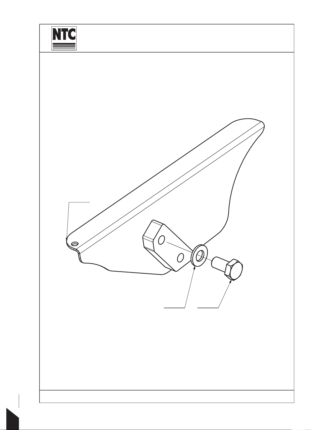
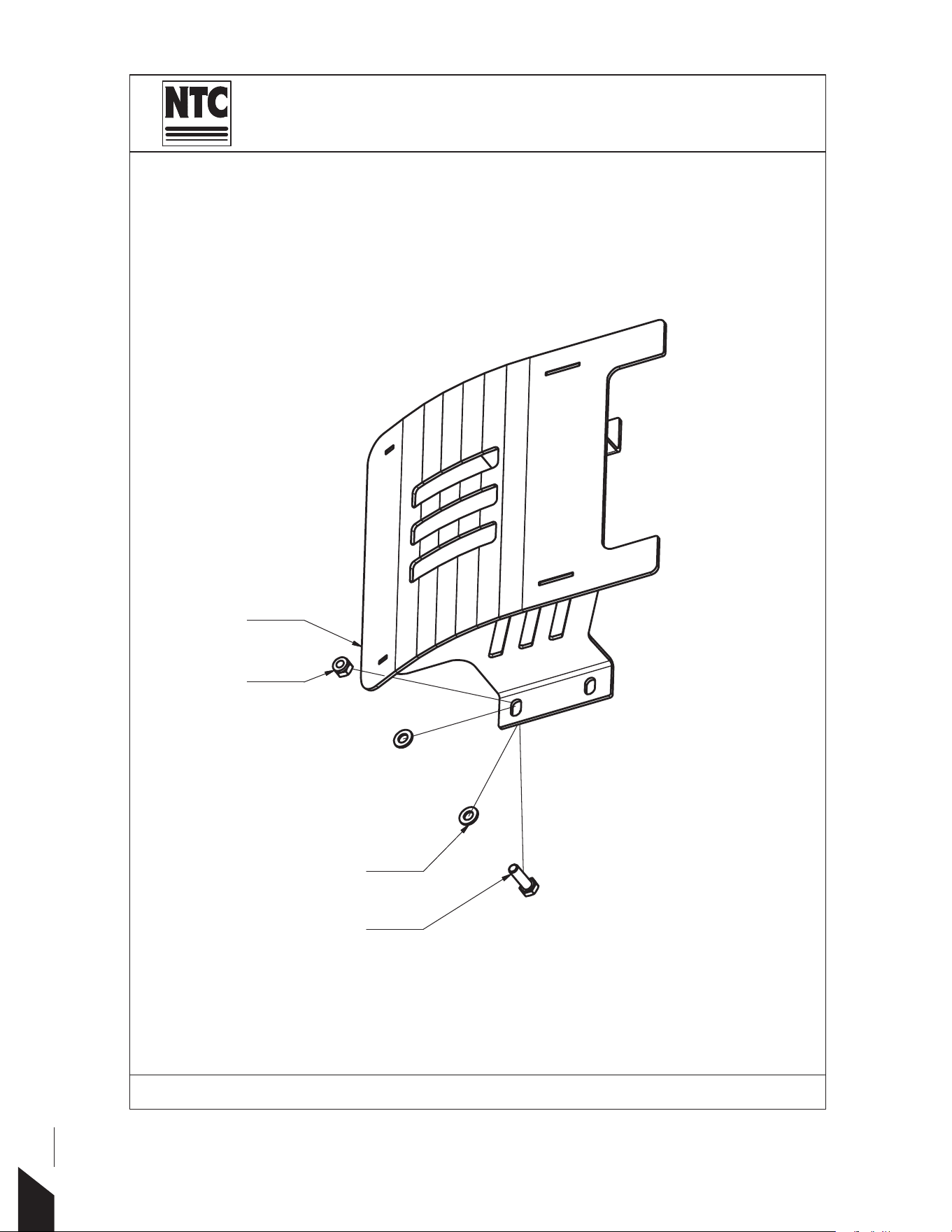
Part Name:
BELT COVER
Machine Type: 73&+
1
3
4

25
LABEL PART NUMBER PART NAME QUANTITY
001 42019A BELT COVER 1
002 2933008016 BOLT 2
003 2125000084 WASHER 3
TOMAHAWK POWER
MACHINE TYPE: TPC90H
26
Part Name:
COVER
Machine Type: 73&+
1
3
4
5

27
LABEL PART NUMBER PART NAME QUANTITY
001 31590A COVER VD 1
003 2933008022 BOLT 4
004 2985000008 NUT 4
005 2125000084 WASHER 8
TOMAHAWK POWER
MACHINE TYPE: TPC90H
28
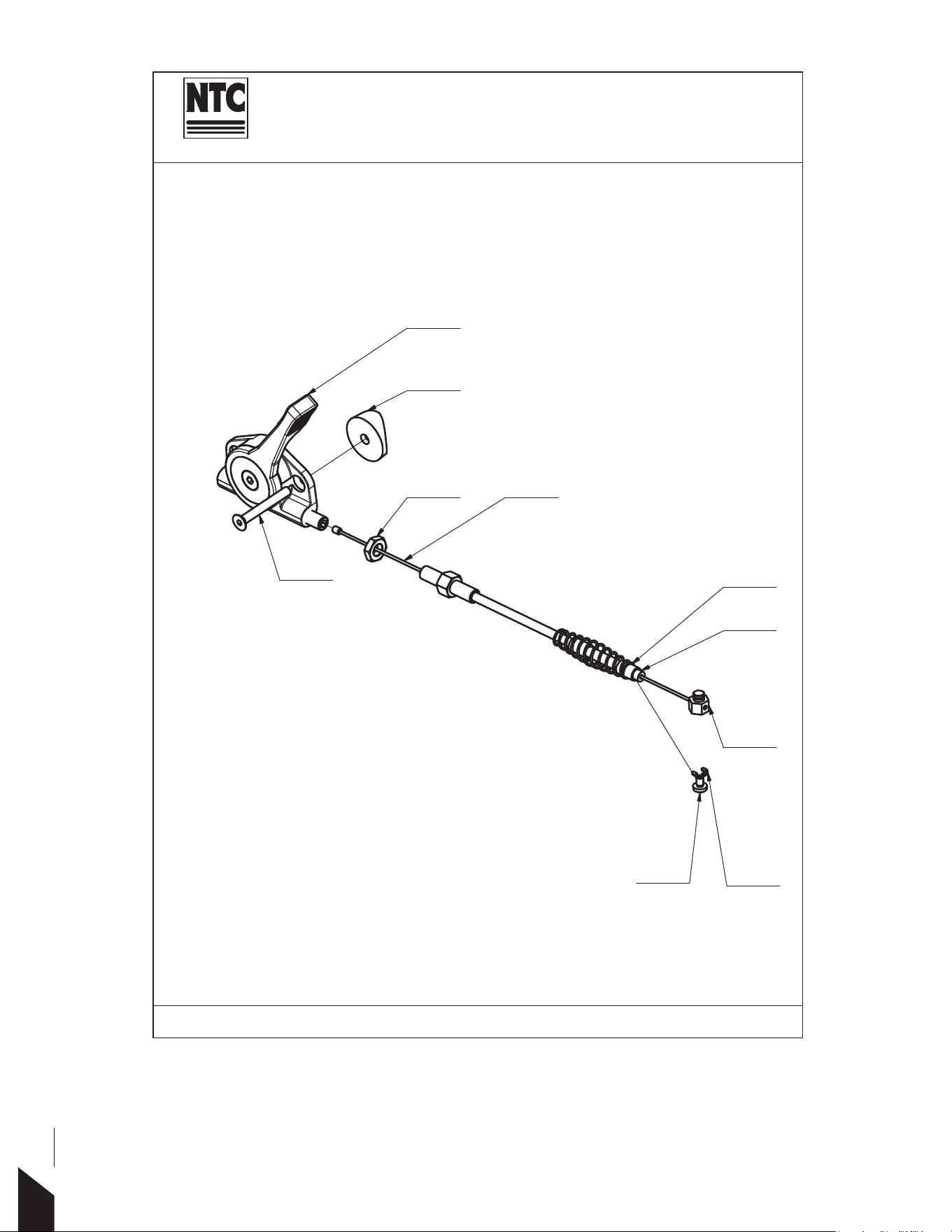
32196A
Part Name:
THROTTLE OPTION
Machine Type: 73&+
6
3
4
8
2
10
9
1
5
7

29
LABEL PART NUMBER PART NAME QUANTITY
001 41786A BOWDEN 1
002 600041787A WIRE 1
003 41238A NUT 1
004 6000000239 LEVEER 1
005 2200000006 SPRING 1
006 2798504006 BOLT 1
007 2934008075 NUT 1
008 3292900005 RING 1
009 2799105040 BOLT 2
010 600041027A WASHER 2
TOMAHAWK POWER
MACHINE TYPE: TPC90H
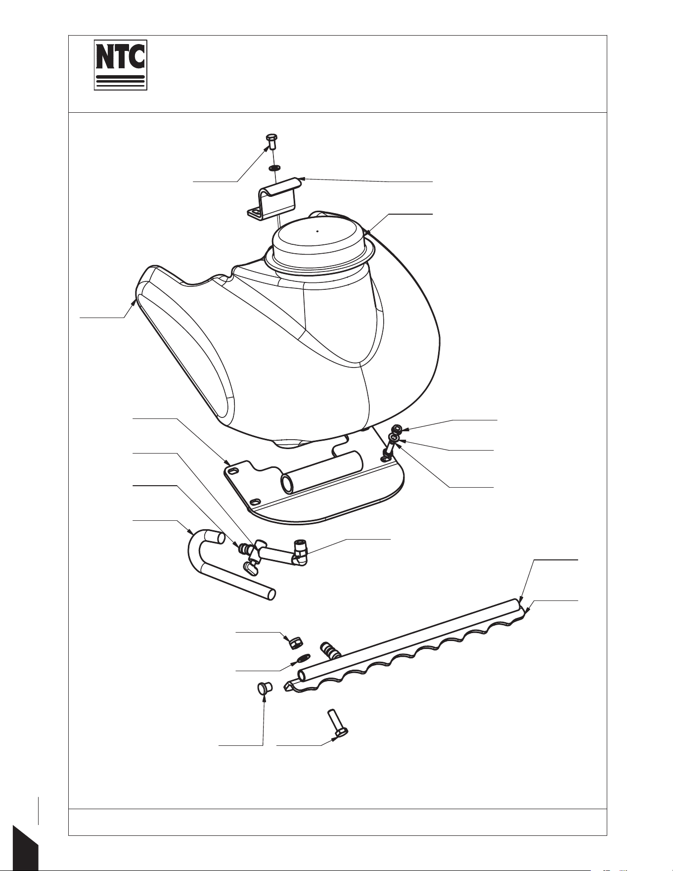
Part Name:
SPRINKL(56<67(0
Machine Type: 73&+
19
17
26
4
2
12
6
14
24
8
21
1
10
15
22
18
11
25
30

31
LABEL PART NUMBER PART NAME QUANTITY
001 41847A PLATE 1
31837A TUBE VD15P 1
31908A TUBE VD18P 1
31860A TUBE VD20P, 24P 1
004 600031326A TANK 1
006 41855A HOLDER 1
008 6000000048 PLUG 1
010 4014435001 WATER TAP 1
011 4014014024 SOCKET 1
012 4014085034 PLUG 2
014 60107 TUBE 1
015 60108 TUBE 1
017 2933010035 BOLT 2
018 2933008025 BOLT 4
019 2933008016 BOLT 2
021 2985000010 NUT 2
022 2985000008 NUT 4
024 2125000105 WASHER 2
025 2125000084 WASHER 10
31818A PLATE VD15P 1
31810A PLAT
E18P 1
31862A PLATE 20P, 24P 1
TOMAHAWK POWER
MACHINE TYPE: TPC90H
002
026
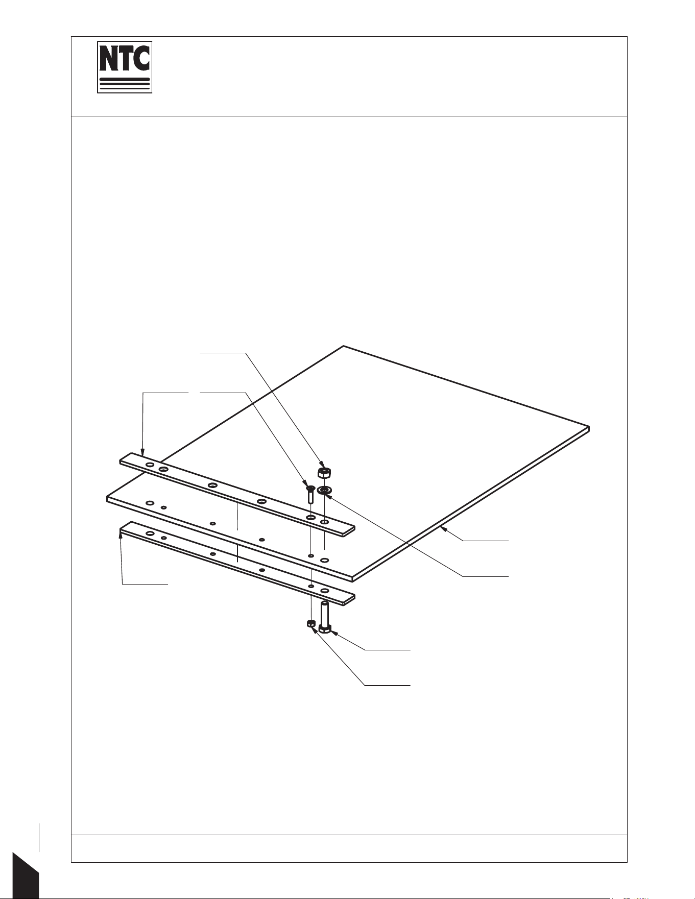
Part Name:
DAMP(1ING PLATE
Machine Type: 73&+
1
5
8
2
3
7
6
9
32

33
LABEL PART NUMBER PART NAME QUANTITY
4013100015 DAMPENING PLATE 1
4013100016 DAMPENING PLATE 1
4013100017 DAMPENING PLATE 1
40093A PLATE I 1
42010A PLATE I 1
41886A PLATE I 1
40094A PLATE II 1
42011A PLATE II 1
41887A PLATE II 1
005 2933010040 BOLT 2
006 2963006025 BOLT 4
007 2985000010 NUT 2
008 2934000006 NUT 4
009 2125000105 WASHER 2
001
002
003
TOMAHAWK POWER
MACHINE TYPE: TPC90H
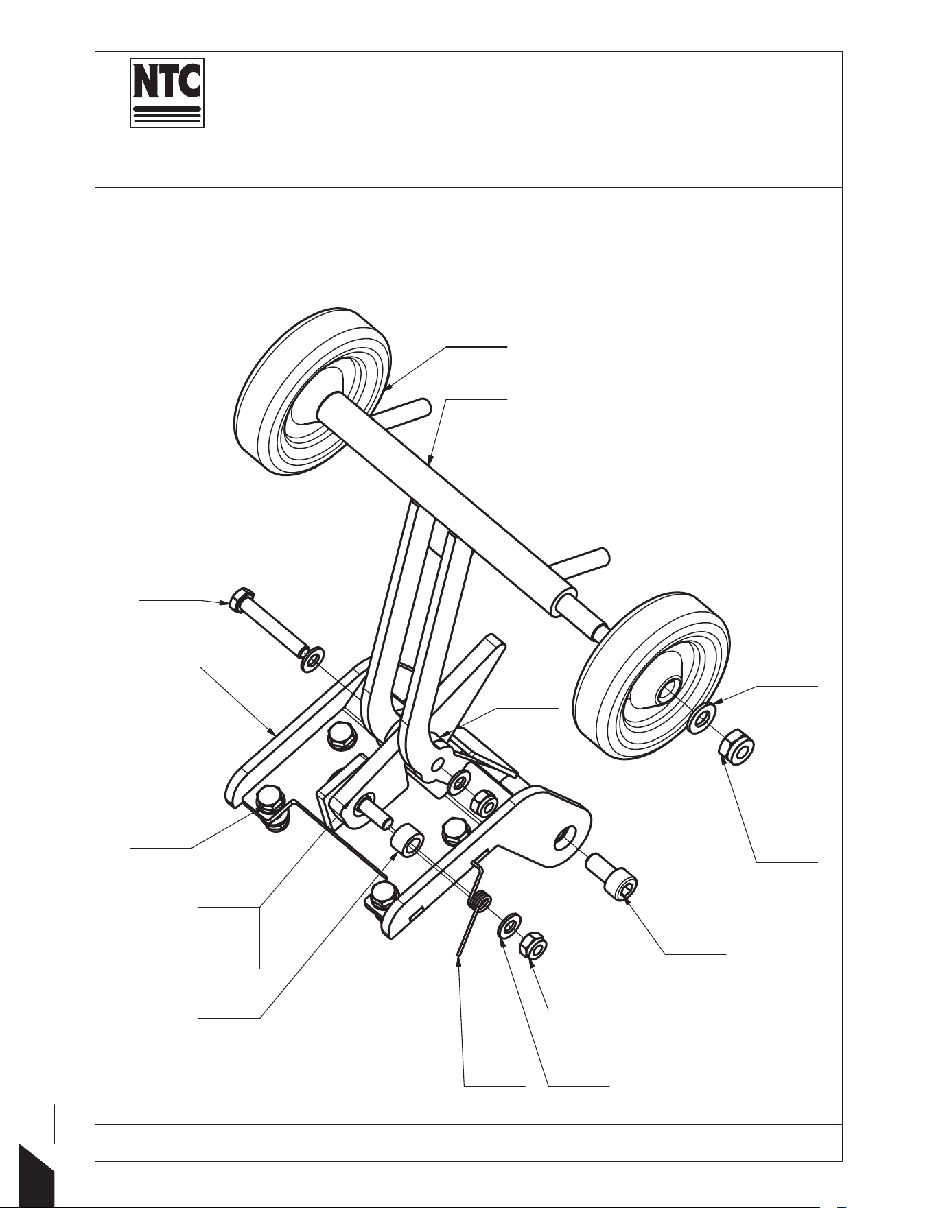
Part Name:
:+((/.,7
Machine Type:
73&+
5
2
10
13
4
18
3
1
6
12
9
14
7
8
16
34

35
LABEL PART NUMBER PART NAME QUANTITY
001 3180180211 WHEEL 2
002 2985000010 NUT 2
003 2125000105 WASHER 2
004 2125000084 WASHER 11
005 2985000008 NUT BOLT 6
006 2933008025 BOLT 4
007 42424B RATCHET 1
008 4014003034 RING 1
009 4014103034 RING 1
010 2200042456 SPRING 1
012 2912010020 BOLT 2
013 31366B FRAME 1
014 31608B FRAME 1
016 42488A ROLLER 1
018 2933008050 BOLT 1
TOMAHAWK POWER
MACHINE TYPE: TPC90H
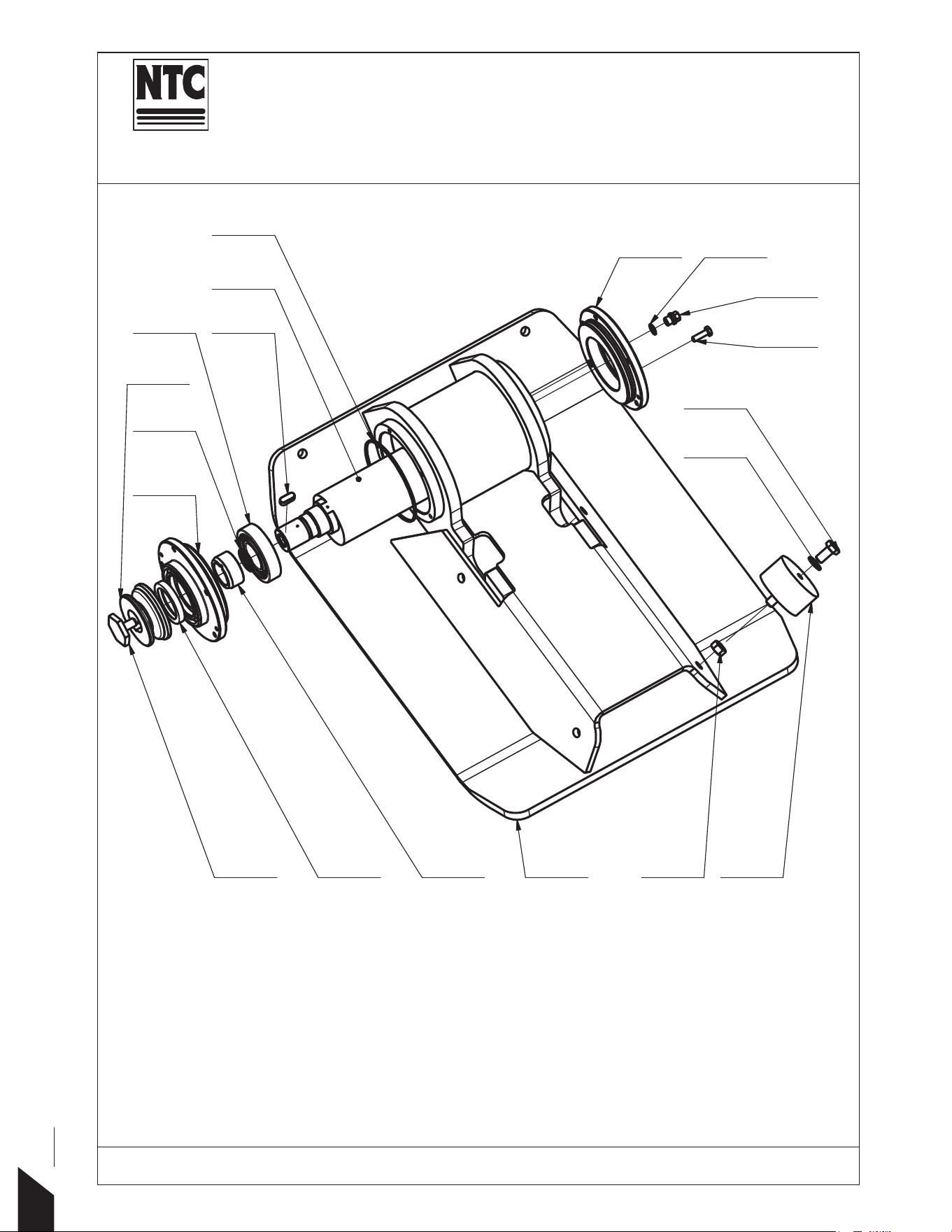
Part Name:
PLATE WITH VIBRATOR
Machine Type: 73&+
1
8
20
5
12
6
18
23
21
1015
4
7
17
11
3
13
16
22
36

37
LABEL PART NUMBER PART NAME QUANTITY
31573A PLATE 1
31574A PLATE 1
31575A PLATE 1
31576A PLATE 1
31387B ECCENTRIC 1
31387A ECCENTRIC 1
31387C ECCENTRIC 1
31466A ECCENTRIC 1
004 31581B COVER I 1
004 31583B COVER I 1
005 31582A COVER II 1
005 31584A COVER II 1
006 31597A PULLEY 1
007 6000040044 RING 1
008 40032A BOLT 1
010 4232124284 SILENTBLOCK 4
011 3110030207 BEARING 1
011 3110030307 BEARING 1
012 3800000015 PLUG 1
013 2256287720 FEATHER 1
015 4104205518 GUFERO 1
016 49281100
02 RING 1
017 4928025526 RING 1
018 3931021014 RING 1
020 2933010020 BOLT 1
021 2933006020 BOLT 1
022 2934000010 NUT 1
023 2125000105 WASHER 1
MACHINE TYPE: TPC90H
001
003
TOMAHAWK POWER
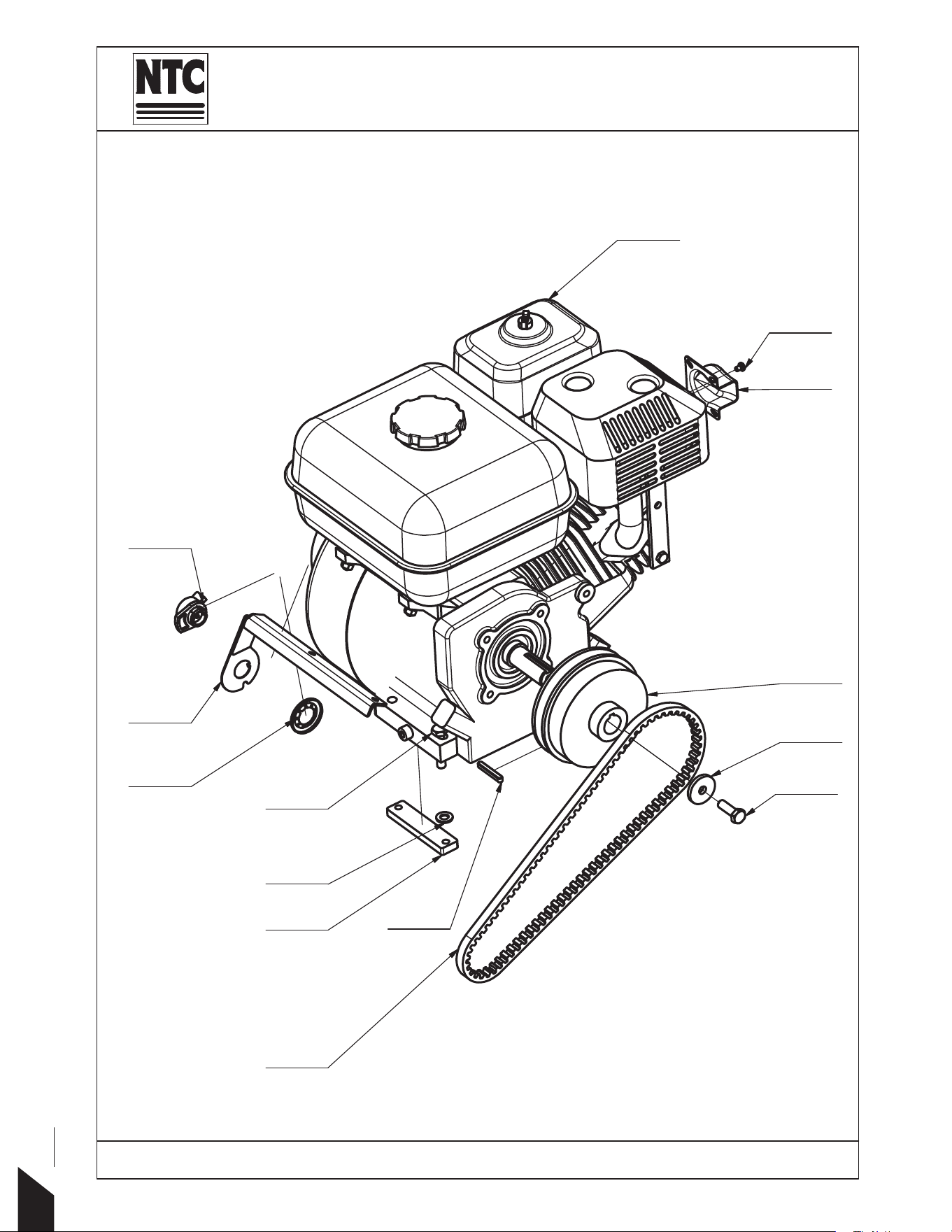
Part Name:
DRIVE
Machine Type: 73&+
16
21
9
11
15
5
6
1
10
19
3
17
12
14
38

39
LABEL PART NUMBER PART NAME QUANTITY
001 41890A HOLDER 1
003 41824A HOLDER 2
005 41061A EXHAUST HONDA 1
006 40172A WASHER 1
009 3120010030 MOTOR 1
010 6000000118 CLUTCH 1
011 4080000785 V-BELT 1
012 3120010030D FEATHER 1
014 2931008040 BOLT 4
015 2798504006 BOLT 2
016 2933008025 BOLT 1
017 2125000084 WASHER 4
019 3200000019 RING 1
021 6800000001 SWITCH 1
TOMAHAWK POWER
MACHINE TYPE: TPC90H
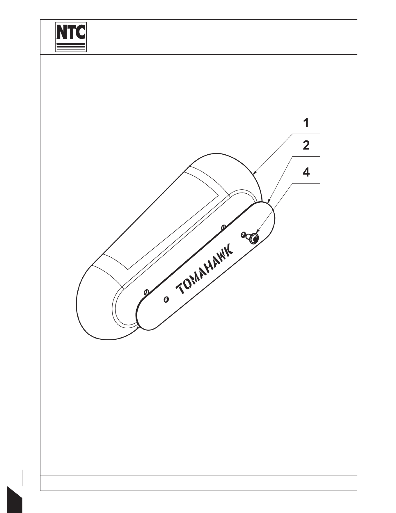
Part Name:
%(/7COVER
Machine Type: 73&+
1
2
4
40

LABEL PART NUMBER PART NAME QUANTITY
001 600031325A COVER 1
002 31364A LOGO 1
004 2738008016 BOLT 2
CHART:
MACHINE TYPE: TPC90H
TOMAHAWK POWER
41
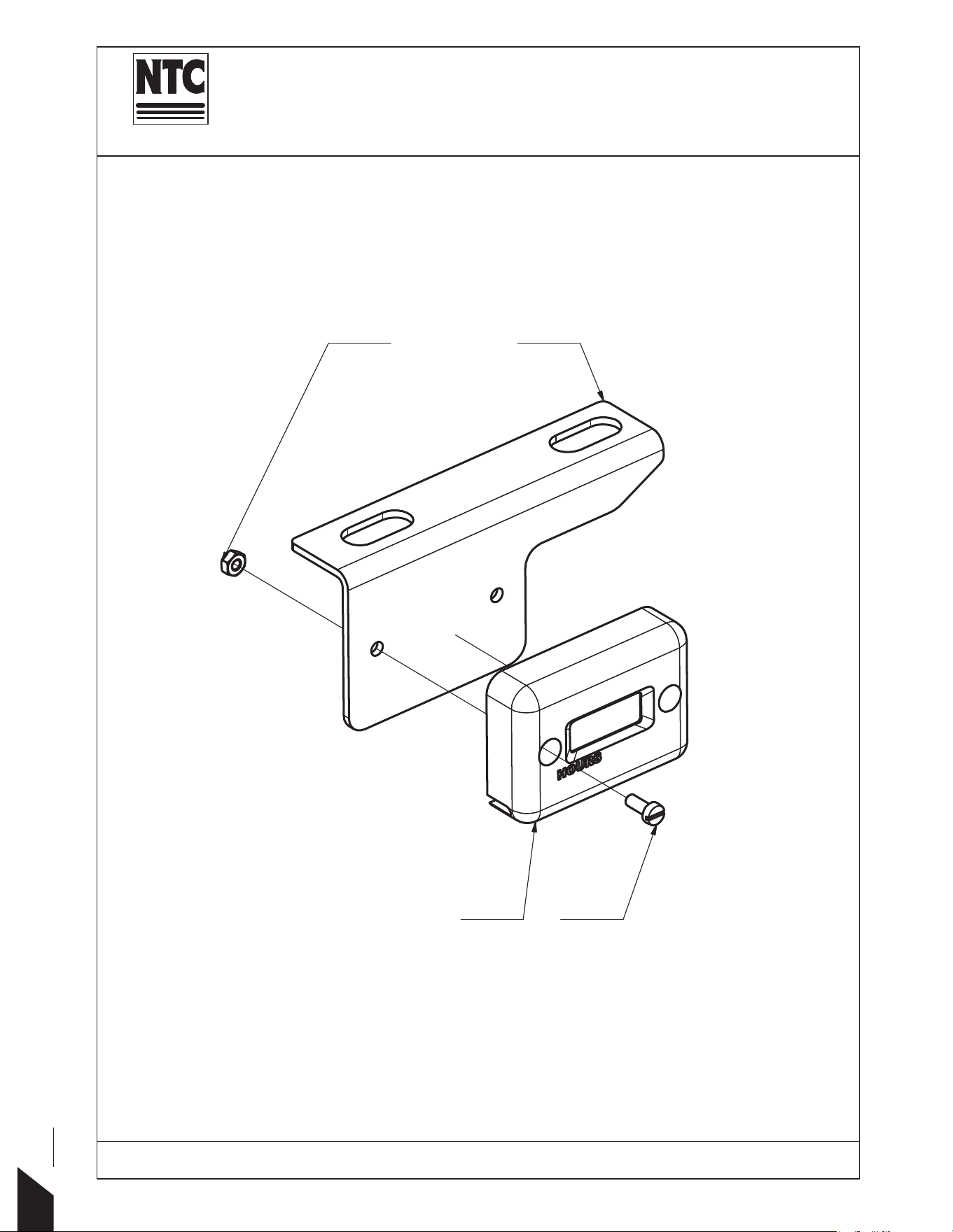
Part Name:
HOUR COUNTER
Machine Type: 73&+
1
5
3
4
42

LABEL PART NUMBER PART NAME QUANTITY
001 41893A HOLDER 1
003 6000000296 HOUR COUNTER 1
004 2840003008 BOLT 2
005 2934000003 NUT 2
TOMAHAWK POWER
MACHINE TYPE: TPC90H
43
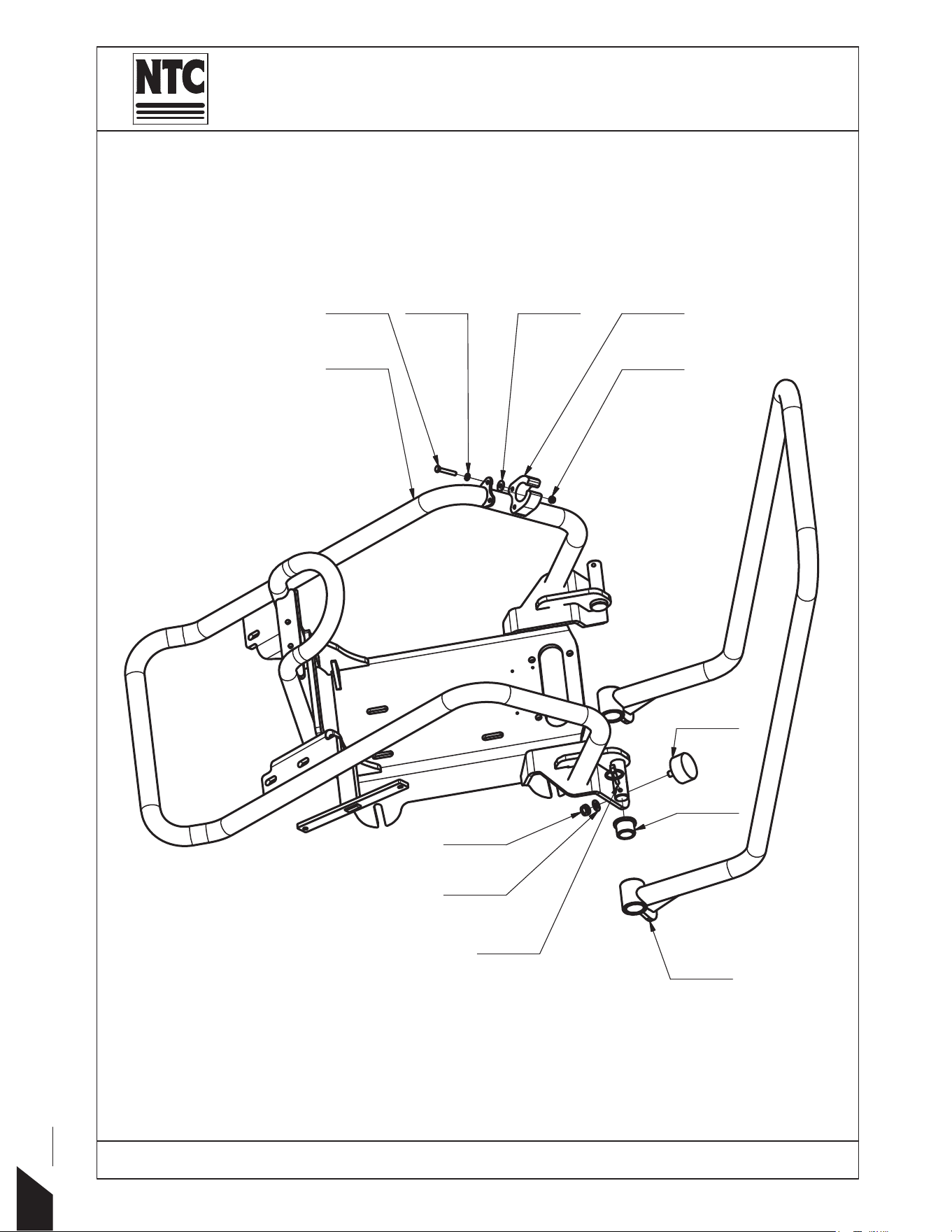
3art Name:
FRAME PRACTIC
Machine Type: 73&+
2
1
7
10 16
4
12
17
15
6
13
8
44

LABEL PART NUMBER PART NAME QUANTITY
001 10098A FRAME 1
002 31604A HANDLEBAR 1
004 600041988A HOLDER 1
006 4236203470 SILENTBLOCK 2
007 4014014033 BUSH 4
008 2200000015 BOLT PIN 2
010 2933005030 BOLT 2
012 2985000008 NUT 2
013 2985000005 NUT 2
015 2125000084 WASHER 2
016 2125000053 WASHER 2
017 2902100005 WASHER 2
TOMAHAWK POWER
MACHINE TYPE: TPC90H
45

46