

Operator's Manual / Manual del usuario
13’’ Corded Grass Trimmer GT1313
Bordeadora Eléctrica de 13 pu GT1313
EN p. 2
Read all safety rules and instructions carefully before operating this tool.
Distributed By Cleva North America 601 Regent Park Court Greenville, SC 29607 1-866-384-8432
Lea todas las regulaciones e instrucciones de seguridad atentamente antes de usar esta herramienta.
Distribuido por Cleva North America 601 Regent Park Court Greenville, SC 29607 1-866-384-8432
MNL_GT1313_V2
ES p. 23
By Nisha Mistry at 8:54 am, Nov 25, 2019

2
PRODUCT SPECIFICATIONS
Type
Voltage
Amp
Speed
Line Size
Trimming Diameter
Trimming Line Length
Weight
2
2
3-4
5-6
7-8
9
10-12
13-14
15-16
17
18
19
20
21-22
Corded
120 V~60Hz
4.2 A
8000 RPM
0.065" (1.65mm)
13" (330mm)
26.2ft (8m)
5.4lbs (2.45 kg)
13” CORDED GRASS TRIMMER
Section Page
CONTENTS
CONTENTS
PRODUCT SPECIFICATIONS
GENERAL SAFETY RULES
ELECTRICAL INFORMATION
SYMBOLS
KNOW YOUR GRASS TRIMMER
ASSEMBLY
OPERATION
MAINTENANCE
TROUBLESHOOTING
WARRANTY
EXPLODED VIEW
PARTS LIST
NOTES

3
READ ALL INSTRUCTIONS AND SAVE THESE INSTRUCTIONS.
When using the grass trimmer the safety rules must be followed. For your own safety and
bystanders please read these instructions before operating the grass trimmer. Do not use the grass
trimmer without reading the instruction sheet. Please keep the instructions safe for later use.
GENERAL SAFETY RULES
WARNING
■ This grass trimmer is designed for cutting grass, soft vegetation, and for edging.
■ The device is not allowed to be used in public gardens, parks, sports centers or at roadsides as well
as in agriculture and forestry.
■ This grass trimmer is not allowed to be used for cutting or chopping, otherwise, there is a risk of
injury. For example:
- Hedges, shrubs and bushes,
- Flowers,
- In terms of composting.
■ Never allow children or people unfamiliar with these instructions to use the trimmer.
■ If the supply cord is damaged, it must be replaced by the manufacturer, its service agent or similarly
qualied persons in order to avoid a hazard.
■ Do not wear loose clothing or jewelry. They can be caught in moving parts. Use of gloves and
substantial footwear is recommended when working outdoors. Wear protective hair covering to
contain long hair.
■ Stop using the grass trimmer while people, especially children, or pets are nearby.
■ Only use the grass trimmer in daylight or good articial light.
■ Ground Fault Circuit Interrupter (GFCI) protection should be provided on the circuit(s) or outlet(s) to
be used for the gardening appliance. Receptacles are available having built-in GFCI protection and
may be used for this measure of safety.
■ Before using the grass trimmer and after any impact, check for signs of wear or damage and repair
as necessary.
■ Never operate the grass trimmer with damaged guards or without the guards in place.
■ Keep hands and feet away from the cutting means at all times and especially when switching on the
motor.
■ To reduce the risk of electric shock, use only with an extension cord intended for outdoor use, such
as an extension cord of cord type SW-A, SOW-A, STW-A, STOW-A, SJW-A, SJOW-A, SJTW-A or
SJTOW-A.
■ Keep proper footing and balance at all times.
■ Take care against injury from any device tted for trimming the lament line length. After extending
new cutter line always return the grass trimmer to its normal operating position before switching on.
■ Never t metal cutting elements.
■ Never use replacement parts or accessories not provided or recommended by the manufacturer.
■ Disconnect the grass trimmer from the outlet before checking, cleaning or working on the grass
trimmer and when it is not in use.
■ Only use identical replacement parts when servicing a tool with double insulation. Servicing should
be performed by a qualied technician.

4
GENERAL SAFETY RULES
■ Always ensure that ventilation openings are kept clear of debris.
■ Avoid unintentional starting. Do not carry plugged-in appliance with nger on switch.
■ Do not abuse the cord. Never carry appliance by the cord or yank it to disconnect from outlet. Keep
the cord from heat, oil, and sharp edges.
■ It will do the job better and with less likelihood of a risk of injury at the rate for which it was designed.
ADDITIONAL SAFETY INSTRUCTIONS FOR YOUR GRASS TRIMMER
■ Do not expose to moisture.
■ Use only on AC outlets supply voltage shown on the product rating label.
■ Avoid operating your trimmer in wet grass, where feasible.
■ Do not use in rain.
■ On slopes, be extra careful of your footing and wear nonslip footwear.
■ Do not walk backwards when trimming, you could trip.
■ Always walk when operating the trimmer, never run.
■ Switch the trimmer off before going over surfaces other than grass.
■ Never pick up or carry a trimmer by the cord.
■ Do not lean over the trimmer guard as objects may be thrown by the cutting line.
■ Keep all nuts, bolts and screws tight to be sure the trimmer is in safe working condition.
■ To avoid the risk of injury keep ngers and hands clear of the line cutter on the leading edge of the
guard.
■ After use, disconnect the machine from the outlet and check for damage.
■ When not in use, tools should be stored indoors in a dry and high, or locked-up place – out of reach
of children.
■ Corded powered trimmers should only be repaired by an authorized technician.
■ Use only manufacturer’s recommended replacement parts and accessories.
■ The preparation for use, operation and maintenance of the appliance:
- Keep cutting edge sharp and clean for best performance and to reduce the risk of injury. Follow
instructions for lubricating and changing accessories. Inspect appliance cord periodically, and if
damaged, have it repaired by an authorized service facility. Inspect extension cords periodically
and replace if damaged. Keep handles dry, clean, and free from oil and grease.
- Read the instructions carefully.
- Be familiar with the controls and proper use of the equipment.
- Before use check the supply and extension cord for signs of damage or aging.
- If the cord becomes damaged during use, disconnect the cord from the power supply immediately.
- Do not use the trimmer if the cords are damaged or worn.
Cutting elements continue to rotate after the motor is switched off; keep extension cords away from
cutting elements.
WARNING
5
DOUBLE INSULATED
This grass trimmer has a plug. The grass trimmer is double insulated to provide a
double thickness of insulation between you and the tool’s electrical system. All
exposed metal parts are isolated from the internal metal motor components with
protective insulation.
GUIDELINES FOR USING EXTENSION CORDS
USE THE PROPER EXTENSION CORD. Make sure your extension cord is
in good condition. When using an extension cord, be sure to use one heavy
enough to carry the current your product will draw. An undersized cord will cause
ELECTRICAL INFORMATION
TO AVOID ELECTRICAL HAZARDS, FIRE HAZARDS, OR DAMAGE TO THE TOOL, USE PROPER
CIRCUIT PROTECTION. YOUR GRASS TRIMMER IS WIRED AT THE FACTORY FOR 120V
OPERATION. CONNECT TO A 120V, 15A CIRCUIT, AND USE A 15A TIME-DELAYED FUSE OR
CIRCUIT BREAKER. TO AVOID SHOCK OR FIRE, IF THE EXTENSION CORD IS WORN, CUT OR
DAMAGED IN ANY WAY, REPLACE IT IMMEDIATELY.
WARNING
WARNING
CAUTION
WARNING
WARNING
USE ONLY IDENTICAL REPLACEMENT PARTS WHEN SERVICING THE GRASS TRIMMER, TO
AVOID INJURY.
ALWAYS MAKE SURE THAT YOUR OUTLET IS PROPERLY GROUNDED. IF UNCERTAIN, HAVE
IT CHECKED BY A CERTIFIED ELECTRICIAN.
DOUBLE INSULATION DOES NOT TAKE THE PLACE OF NORMAL SAFETY PRECAUTIONS
WHEN OPERATING THIS GRASS TRIMMER.
THIS GRASS TRIMMER IS FOR OUTDOOR USE ONLY. DO NOT EXPOSE TO RAIN OR USE IN
DAMP LOCATIONS.

6
ELECTRICAL INFORMATION
overheating. The table below shows the correct size to use depending on cord
length and nameplate ampere rating. If in doubt, use the next heavier gauge. The
smaller the gauge number, the heavier the cord.
Make sure your extension cord is properly wired and in good electrical condition.
Always replace a damaged extension cord or have it repaired by a qualied
person before use. Keep extension cords away from sharp objects, excessive
heat and damp or wet areas.
Use a separate electrical circuit for your tools. This circuit should comprise a
wire of at least 12 gauge and should be protected with a 15A time-delayed fuse.
Before connecting the motor to the power line, make sure the switch is in the
OFF position and the electric current is identical to that stamped on the motor
nameplate. Running at a lower voltage will damage the motor.
Minimum Gauge for Extension Cords (AWG)
(Using 120 V only)
Total Length of Cord in Feet (meters)
120V 25ft (7.62m) 50ft (15.24m) 100ft (30.48m) 150ft (45.72m)
Ampere Rating
AWG
More Than
Not More
Than
0 6 18 16 16 14
6 10 18 16 14 12
10 12 16 16 14 12
12 16 14 12 Not Recommended
WARNING
SAVE THESE INSTRUCTIONS.
ALTHOUGH THIS GRASS TRIMMER IS DOUBLE INSULATED, THE EXTENSION CORD AND
RECEPTACLE MUST STILL BE GROUNDED WHILE IN USE TO PROTECT THE OPERATOR
FROM ELECTRICAL SHOCK.

7
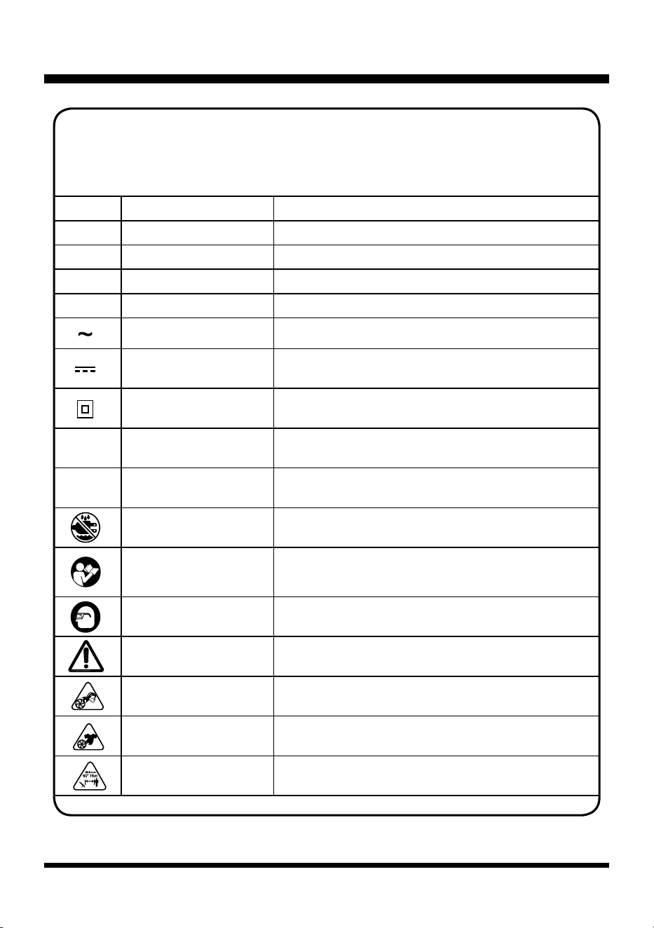
SYMBOLS
SYMBOL NAME DESIGNATION/EXPLANATION
V Volts Volts
A Amperes Current
Hz Hertz Frequency (cycles per second)
W Watts Power
min Minutes Time
Alternating Current Type of current
Direct Current Type or a characteristic of current
Class II Construction Double-insulated construction
No Load Speed Rational speed, at no load
/min Per Minute
Revolution, strokes, surface speed, orbits etc, per
minute
Wet Conditions Alert Do not expose to rain or use in damp locations.
Read the Operator’s
Manual
To reduce the risk of injury, user must read and
understand Operator’s Manual before using this
product.
Eye Protection
Always wear eye protection with side shields marked
to comply with ANSI Z87.1.
Safety Alert Precautions that involve your safety
Long Hair
Failure to keep long hair away from the air inlet could
result in personal injury
Loose Clothing
Failure to keep loose clothing from being drawn into
air intake could result in personal injury.
Keep Bystanders Away Keep all bystanders at least 50' (15 m) away.
Some of the following symbols may be used on this product. Please study them and
learn their meaning. Proper interpretation of these symbols will allow you to operate
the product better and safer.
n
o
8
SYMBOLS
SYMBOL SIGNAL MEANING
DANGER
Indicates an imminently hazardous situation, which, if not
avoided, will result in death or serious injury.
WARNING
Indicates a potentially hazardous situation, which, if not
avoided, could result in death or serious injury.
CAUTION
Indicates a potentially hazardous situation, which, if not
avoided, may result in minor or moderate injury.
NOTICE
(Without Safety Alert Symbol) Indicates a situation that may
result in property damage.
The following signal words and meanings are intended to explain the levels of risk
associated with this product.
9
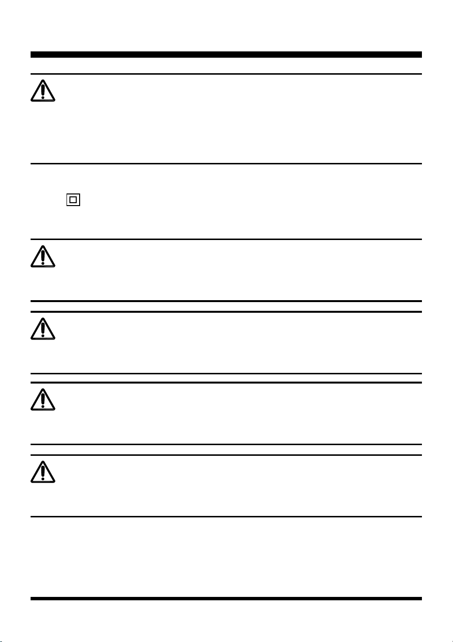
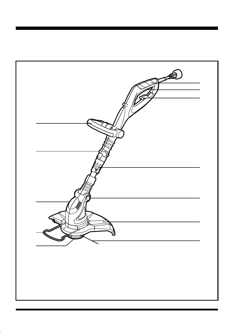
KNOW YOUR GRASS TRIMMER
The safe use of this product requires an understanding of the information on the product and in
this Operator’s Manual as well as a knowledge of the project you are attempting. Before use of this
product, familiarize yourself with all operating features and safety rules.
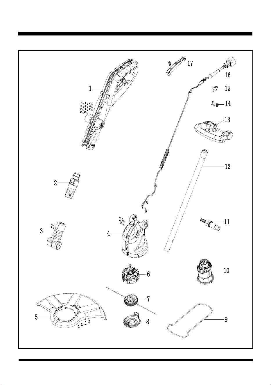
Components
1. Upper Handle
2. ON/OFF Switch
3. Cord Retainer Hook
4. Height Adjustment Locking Collar
5. Pivot Head Button
6. Debris Guard
1
8
9
10
11
12
2
3
4
5
6
7
7. Trimming Line
8. Line Spool
9. Flower Guard
10. Motor Housing
11. Rotational Lock Button
12. Assist Handle
10
ASSEMBLY
WARNING
Before assembly, make sure that the grass trimmer is switched off and unplugged.
This product requires assembly.
■ Carefully remove the product and any accessories from the box. Make sure that all items listed in
the packing list are included.
■ Inspect the product carefully to make sure no breakage or damage occurred during shipping.
■ Do not discard the packing material until you have carefully inspected and satisfactorily operated
the product.
■ If any parts are damaged or missing, please call the service center.
PACKING LIST
(1) Grass Trimmer (with trimmer head and line spool installed)
(1) Assist Handle
(1) Wing Nut with Bolt
(1) Debris Guard (2 halves)
(1) Flower Guard
(1) Operator's Manual
(4) Screws
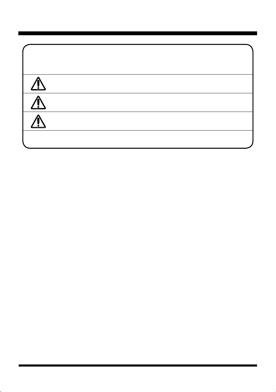
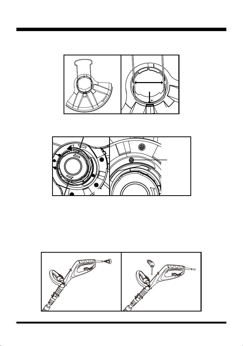
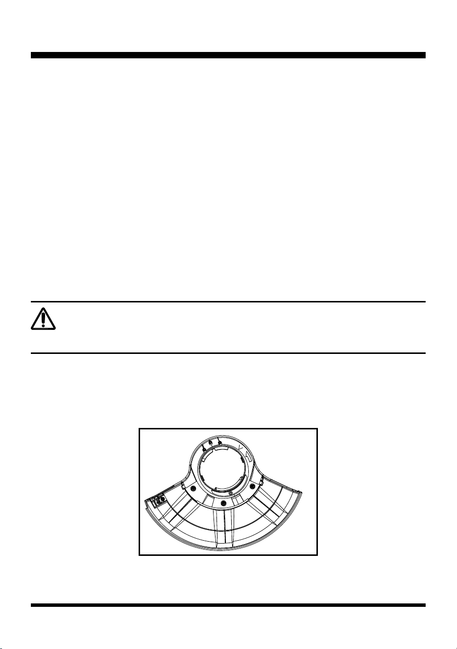
INSTALLING THE FLOWER GUARD AND DEBRIS GUARD (See Figs. 1-5)
■ Assemble the 2 halves of the debris shield together by aligning and “snapping” together.
■ Secure the debris guard with 3 screws. (Fig. 1).
Fig. 1
11
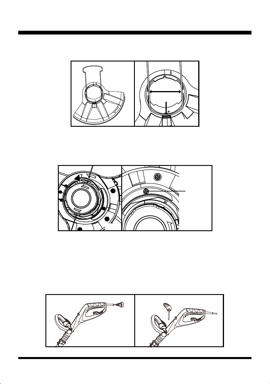
ASSEMBLY
■ Position steel ower guard and snap into the debris guard as shown. The ower guard must be placed
under the plastic tabs (Fig. 2 & 3).
■ With ower guard extended, place entire debris guard with ower guard over the spool head and align it.
■ Once aligned, rotate debris/ ower guard assembly so the two screw holes align as shown (Fig. 4 & 5).
■ Use remaining screw to fasten the assembly to the motor housing.
FITTING THE ASSIST HANDLE (See Figs. 6-7)
■ Place the assist handle on the grass trimmer as shown (Fig. 6).
■ Adjust the assist handle to the most comfortable position. Use the marking as a guide.
■ Pass the bolt through the assist handle and the upper handle (Fig. 7).
■ Screw the nut into the other side of the bolt. Do not over tighten the bolt.
Fig. 7
Fig. 6
Fig. 2
Fig. 4
Plastic Tabs
Align
Holes
Fig. 3
Fig. 5
12
ASSEMBLY
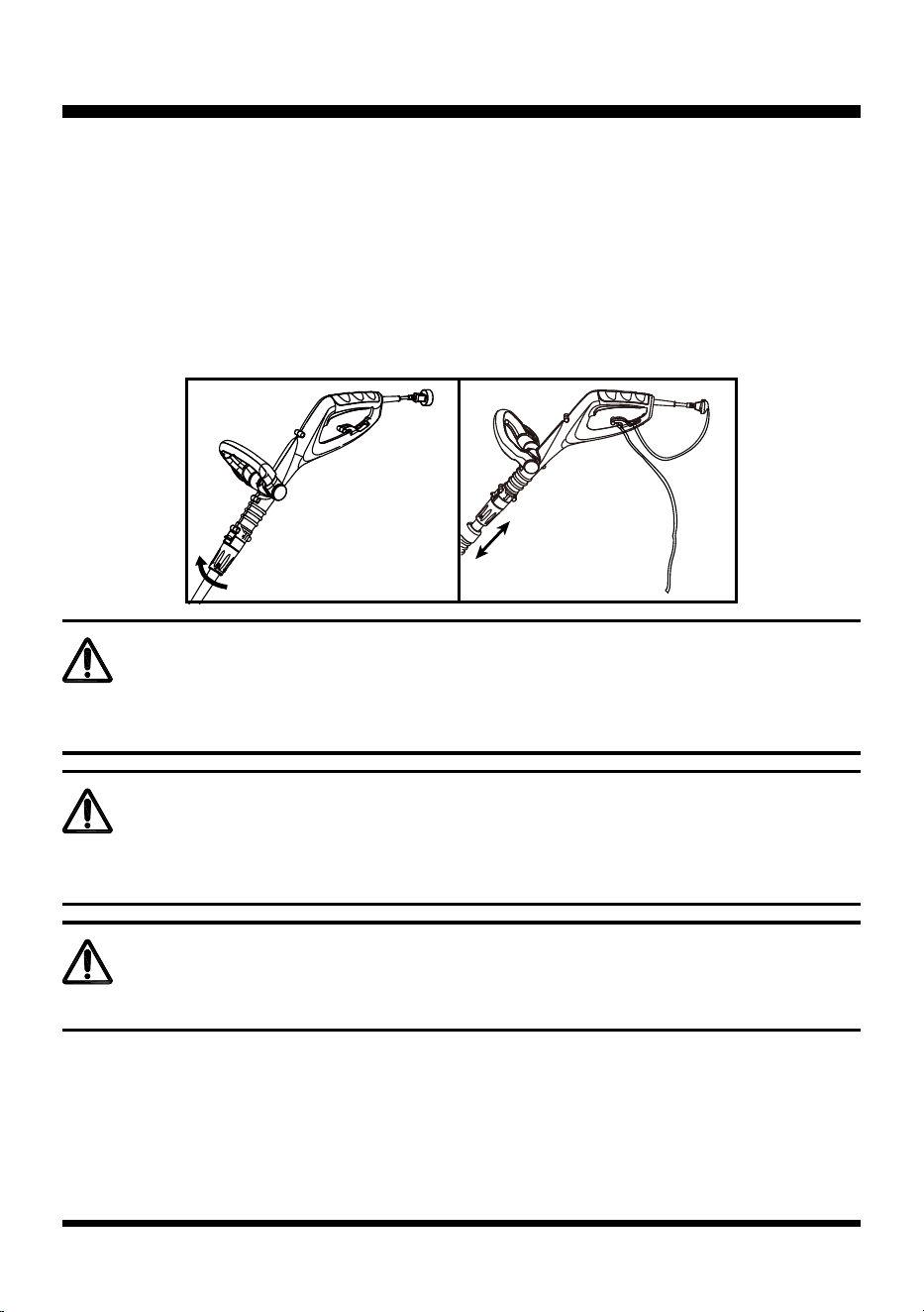
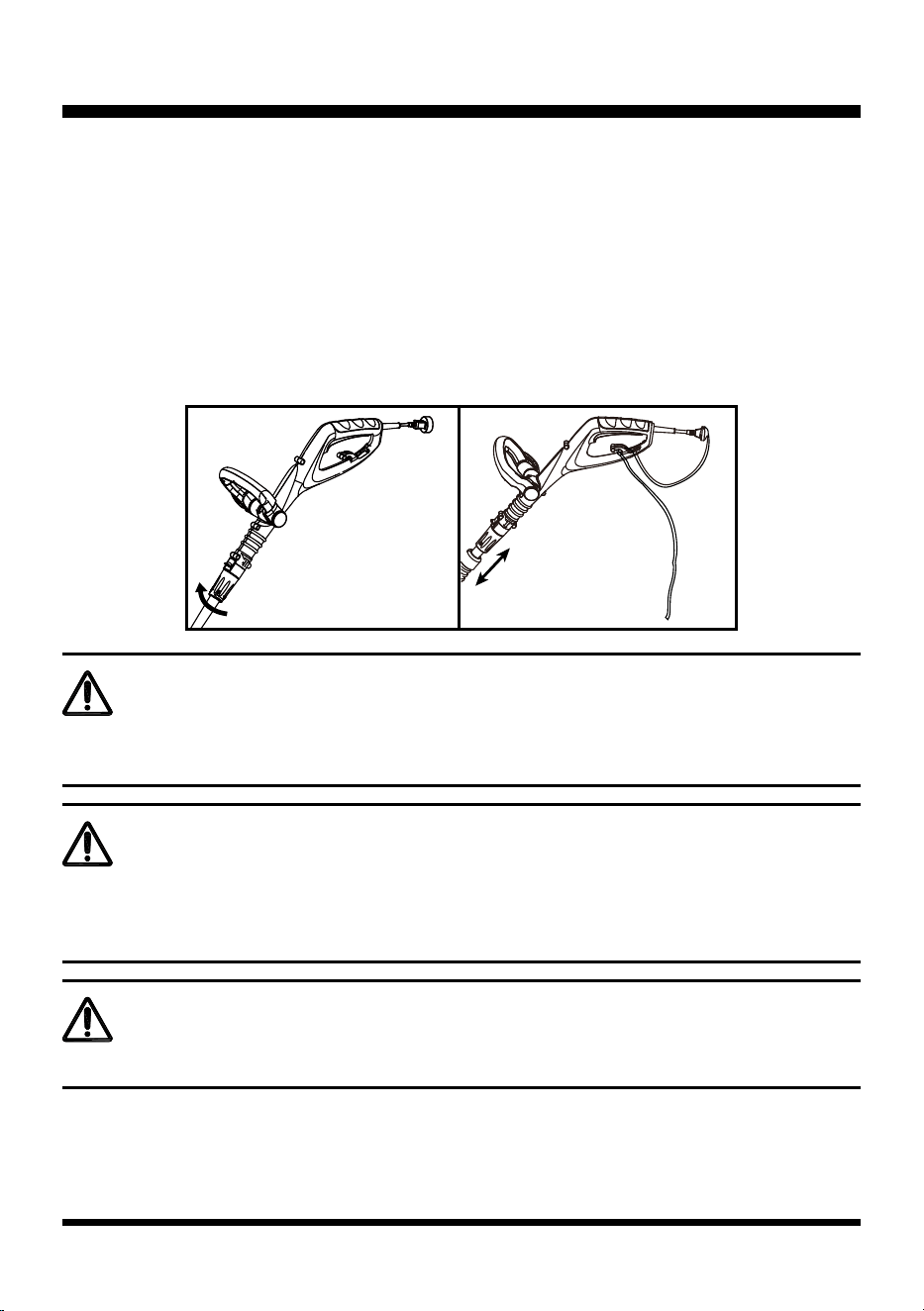
PREPARING THE TRIMMER FOR USE (See Figs. 8-9)
■ Turn the adjustment collar clockwise to unlock, you can slide the telescopic tube up or down to achieve
comfortable working height (Fig. 8 & 9).
■ Turn the adjustment collar counter-clockwise till the shaft locks into place.
■ Route the extension cord through the slot located on the rear of the grass trimmer housing and place
underneath the cord retainer (Fig. 9).
■ To start the grass trimmer, press the ON/OFF switch.
■ To stop the grass trimmer, release the ON/OFF switch.
WARNING
WARNING
WARNING
If any parts are damaged or missing, do not operate this product until the parts are replaced.
Failure to heed this warning could result in serious personal injury.
Do not connect to power supply until assembly is complete.
Failure to comply could result in accidental starting and possible serious personal injury.
Never attempt to lock the on/off switch in the on position.
Fig. 9
Fig. 8
13
OPERATION
HINT FOR OPTIMUM USE
In order to achieve optimum cutting results, only cut dry grass.
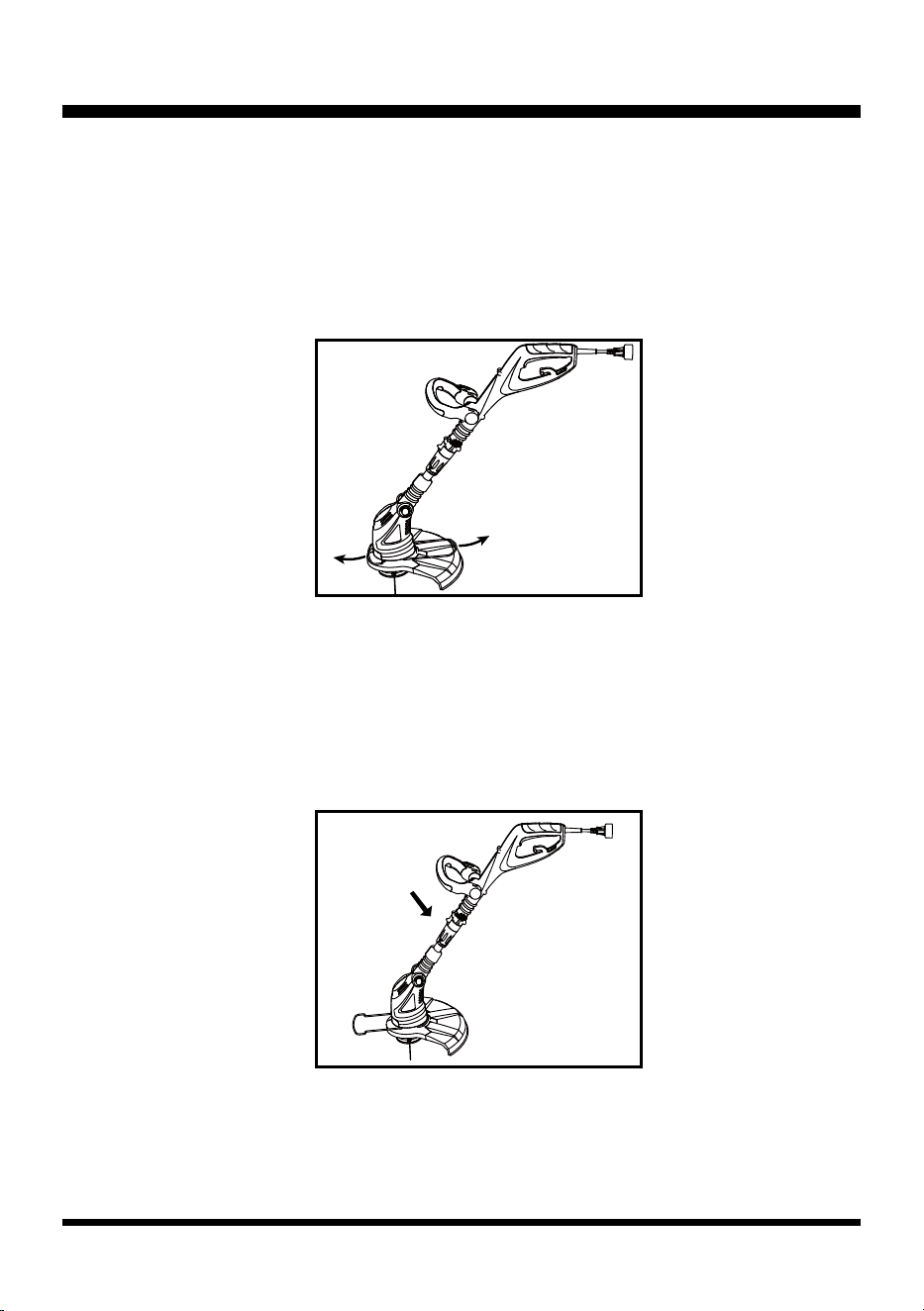
TRIMMING (See Fig. 10)
■ Hold the grass trimmer.
■ Gently swing the trimmer from side to side (Fig. 10).
■ When cutting long grass, work in stages from hard objects and delicate pants.
■ If the grass trimmer starts running slowly, reduce the load.
ADJUSTING HEAD ANGLE (See Fig. 11)
Depress the button and pivot the trimmer head to the lowest position. Once the head is in the 4th position,
release the button and the trimmer head will lock into place (Fig. 11).
Fig. 10
Fig. 11
14
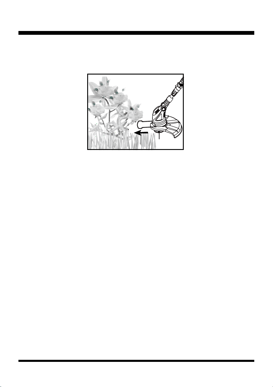
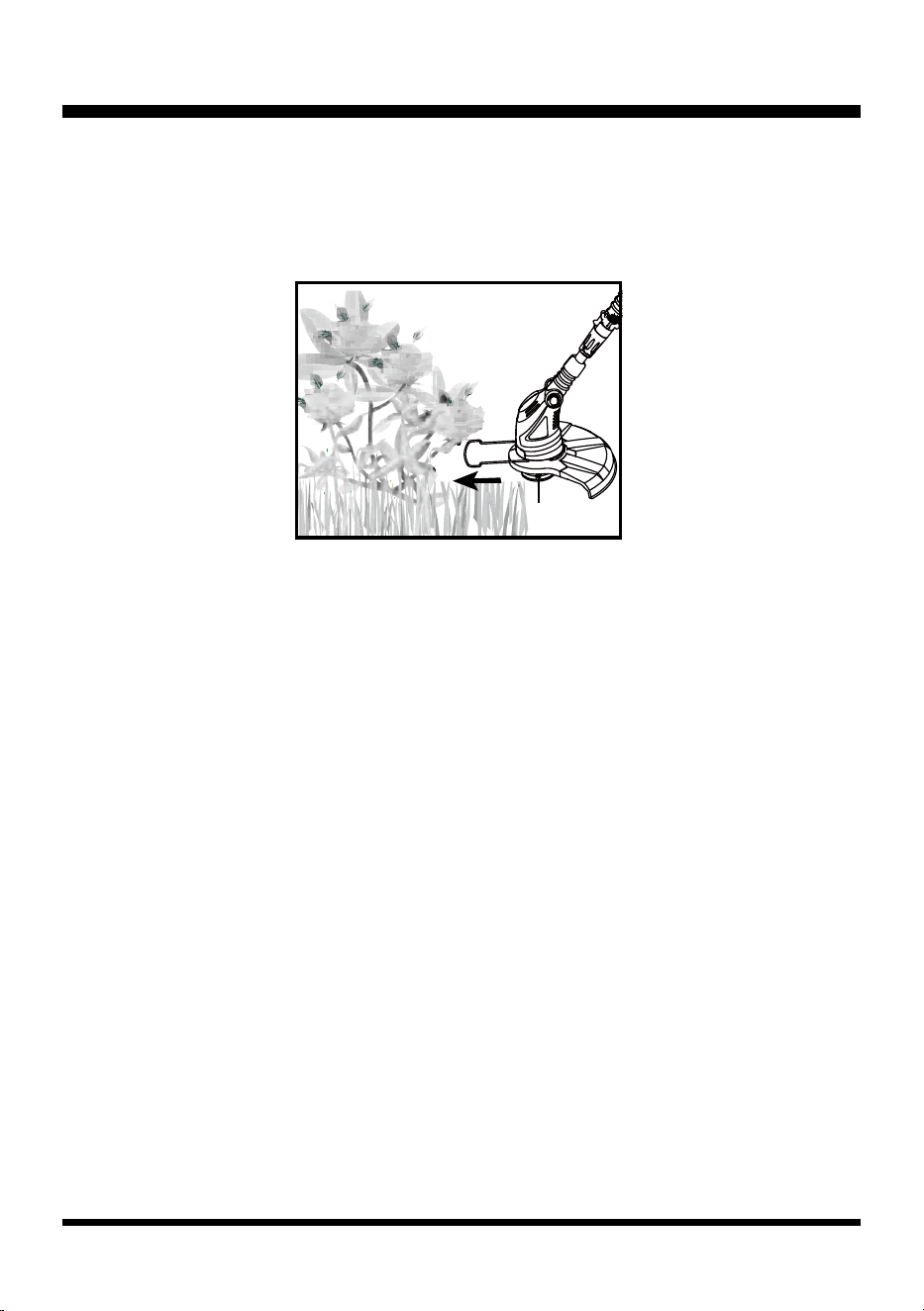
USING THE FLOWER GUARD (See Fig. 12)
If necessary the ower guard can be pulled from the debris guard as shown. Use the
ower guard, for example, to cut around plants (Fig. 12).
IF GRASS WRAPS AROUND THE TRIMMER HEAD
■ Stop the trimmer
■ Unplug the trimmer.
■ Remove the grass.
ADVANCING LINE
NOTE: This trimmer is equipped with an auto-feed head.
Do not bump the head to try to advance the line will damage trimmer and void warranty.
■ With the trimmer running, release the ON/OFF switch.
■ Wait two seconds, and press the ON/OFF switch.
NOTE: The auto-feed function works during the starting and stopping of trimmer. Line will extend
approximately 3/16 in. with each stop and start of ON/OFF switch WHILE NOT TRIMMING until the line
reaches the length of the grass deector blade. It may take up to 10 complete starting and stoppings to
advance the line.
Fig. 12
OPERATION
15
MAINTENANCE
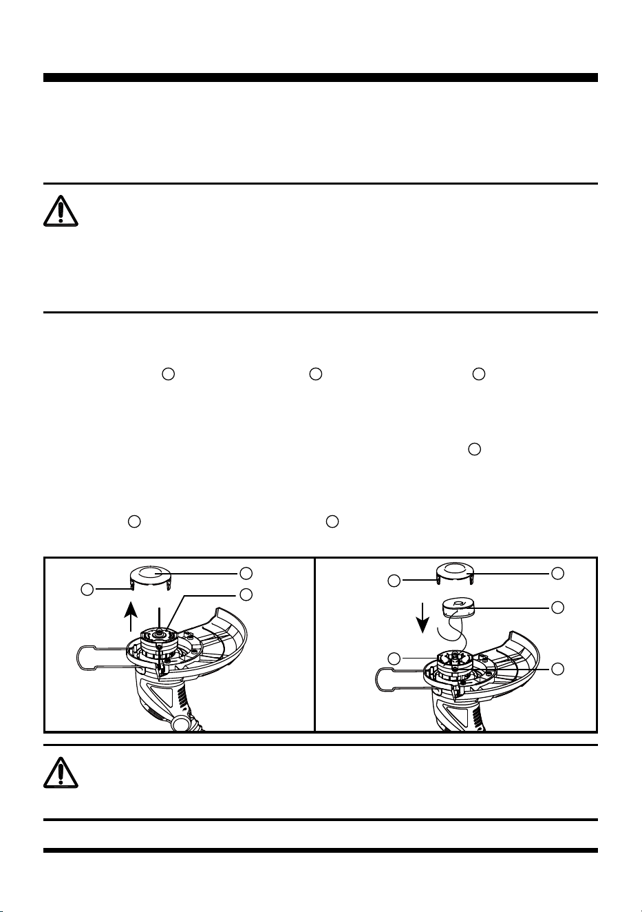
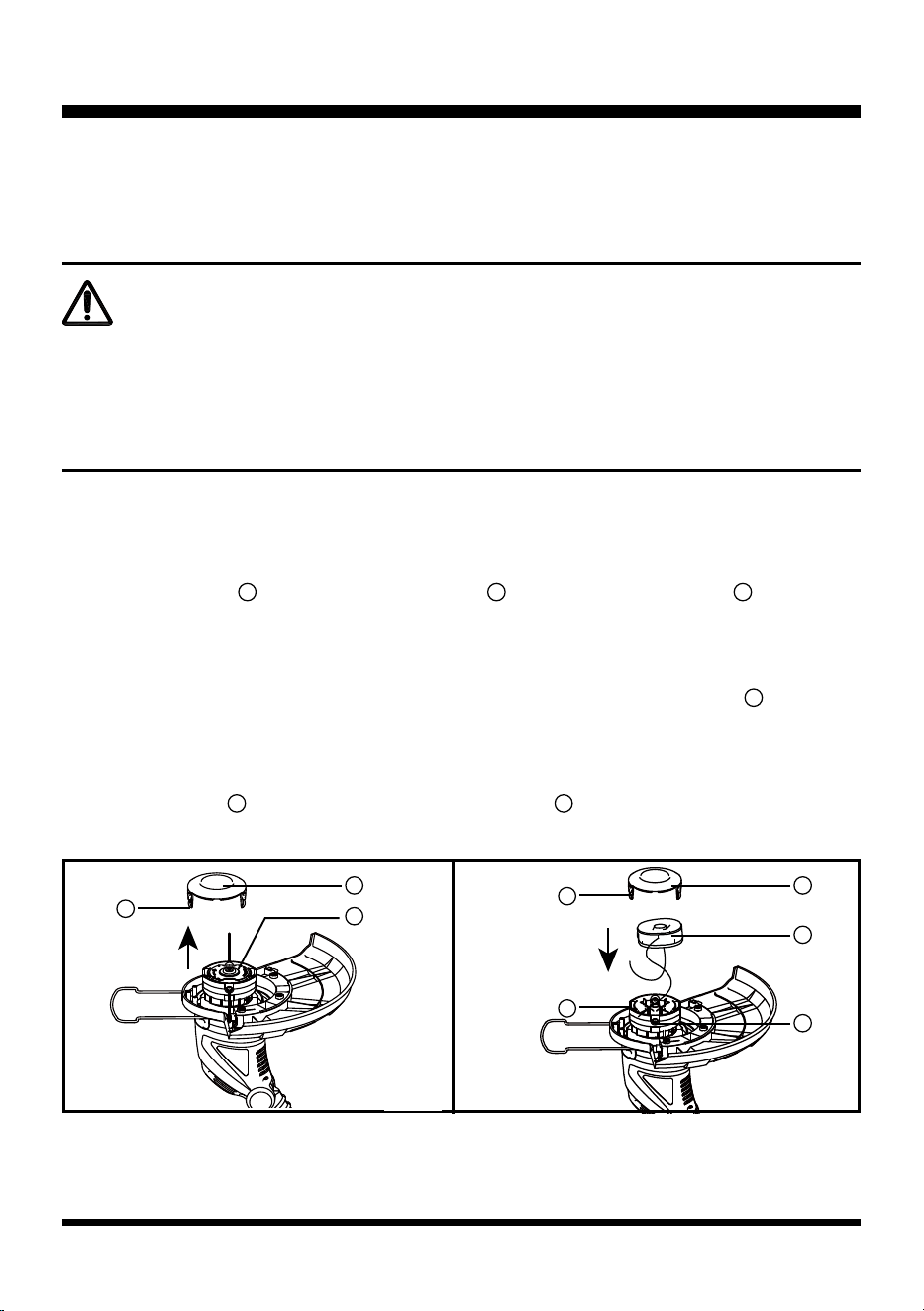
FITTING A NEW SPOOL HEAD (See Figs. 13-14)
■ Unplug the grass trimmer.
■ To remove the spool , depress the thumb tabs and remove the spool cover from the housing,
then remove the empty spool (Fig. 13).
■ Remove any dirt and grass from the spool cover and housing.
■ Place the new spool into the housing, Rotate the spool slightly until it is seated (Fig. 14).
■ Unclip the end of one of the cutting lines and guide the line into one of the eyelets . The line should
protrude approx. 4 inches from the spool housing.
■ Unclip the end of the other cutting line and guide the line into the other eyelet. The line should produce
approx. 4 inches from the spool housing.
■ Align the tabs on the spool cover with the cut outs in the housing.
■ Push the cover onto the housing until it snaps securely into place.
Your grass trimmer has been designed to operate over a long period of time with
minimum maintenance. Continuous satisfactory operation depends upon proper tool
care and regular cleaning.
WARNING
Before performing any maintenance, switch off and unplug the tool.
• Regularly clean the ventilation slot in your grass trimmer using a soft brush or dry cloth.
• Regularly clean the cutting line and spool using a soft brush or dry cloth.
• Regularly use a blunt scraper to remove grass and dirt from the underneath the guard.
Fig. 14
Fig. 13
WARNING
If the cutting lines protrude beyond the trimming blade, cut them down to the length of the blade.
1
1
2
2
2
2
5
5
3
3
3
1
4
4
16
MAINTENANCE
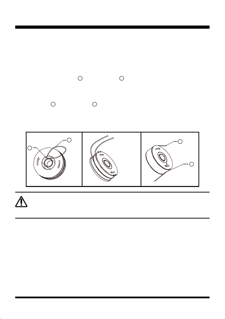
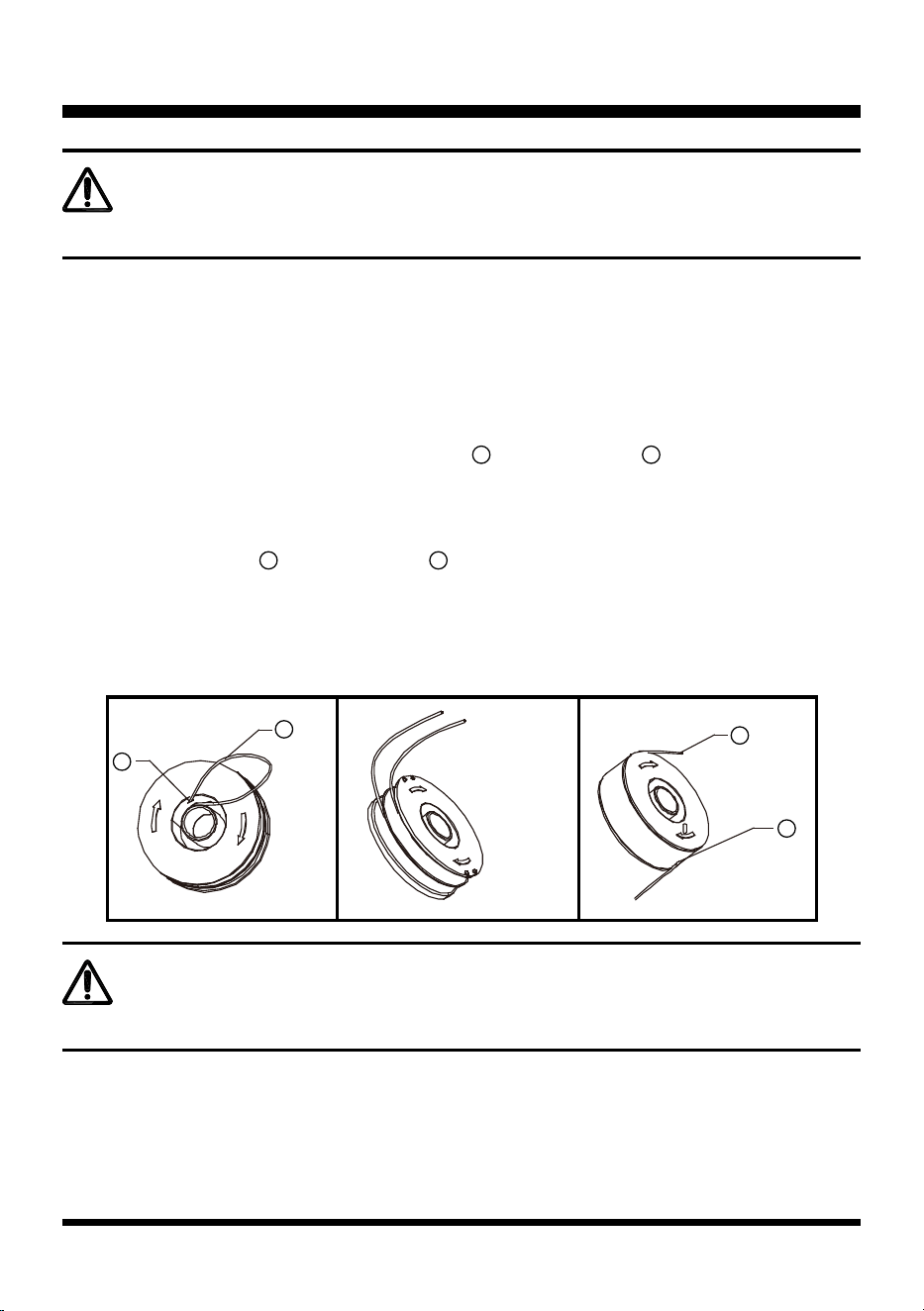
WINDING NEW LINE ONTO A SPOOL (See Figs. 15-17)
■ Only use .065" replacement line.
■ You may wind new cutting line onto an empty spool.
■ Replacement packs of cutting line are available from dealer.
■ Remove the empty spool from the grass trimmer as described above.
■ Remove any remaining cutting line from the spool.
■ First feed 4 inches of cutting line into the two eyelets in the upper section of the spool as shown (Fig.
15).
■ Wind the cutting line onto the spool in the direction of the arrow. Make sure to wind the line on neatly and in
layers. Do not criss-cross (Fig. 16).
■ Feed cutting line into the two eyelets in the upper section of the spool as shown (Fig. 17).
■ If you want to use, operate as described above to x the spool on the grass trimmer. Do not forget to
release the cutting lines from the parking slot.
Use LawnMaster
®
replacement spool; part NO. RS0101
WARNING
Only use the appropriate type of cutting line.
Fig. 17Fig. 16
Fig. 15
6
6
6
6
7
7
7
1

17
TROUBLESHOOTING
If your grass trimmer does not appear to operate properly, follow the instructions below.
If the instructions below do not solve the problem, please contact your local service center.
WARNING
Before proceeding, switch off your grass trimmer and unplug.
PROBLEM POSSIBLE CAUSE SOLUTION
The trimmer does not
start.
The power cord is not
properly connected to
power source.
Check that the power cord is properly
connected and that there is power going
to trimmer.
Defective ON/OFF switch. Repair by a qualied personal.
The trimmer runs slowly.
The spool housing is
blocked.
Check that the spool housing can rotate
freely. Carefully clean it if necessary.
The cutting line protrudes
too long.
Check that the cutting line does not
protrude more than 4 inches from the
spool housing. If it does, cut it off so that
it just reaches the line trimming blade.
Unsatisfactory result.
The cutting line is worn or
damaged.
Replace the spool.
Automatic line feed does
not work.
Insufcient cutting line.
Keep the tabs depressed and remove
the spool cover from the housing. Pull
the cutting line until it protrudes 4 inches
from the housing. If insufcient cutting
line is left on the spool, install a new
spool of cutting line as instructed in
FITTING A NEW SPOOL section.
The spool is jammed.
Carefully clean the spool cover and
housing.
Remove the spool and check if the lever
can move freely.
Remove the spool and unwind the
cutting line, then wind it on neatly again
as instructed in WINDING NEW LINE
ONTO A SPOOL section. Replace the
spool as instructed.

18
WARRANTY
We take pride in producing a high quality, durable product. This Lawnmaster
®
product carries a limited two (2)
year warranty against defects in workmanship and materials from date of purchase under normal household
use. If product is to be used for commercial, industrial or rental use, a 30 day limited warranty will apply.
Warranty does not apply to defects due to direct or indirect abuse, negligence, misuse, accidents, repairs,
alterations and lack of maintenance. Please keep your receipt/packing list as proof of purchase. This warranty
gives you specic legal rights, and you may have other rights, which vary from state to state. For product
service call Customer Service at 1-866-384-8432.
Items not covered by warranty:
1. Any part that has become inoperative due to misuse, commercial use, abuse, neglect, accident, improper
maintenance, or alteration;
2. The unit, if it has not been operated and/or maintained in accordance with the Operator's Manual;
3. Normal wear, except as noted below;
4. Routine maintenance items such as lubricants, blade sharpening;
5. Normal deterioration of the exterior nish due to use or exposure.
Transportation Charges: Transportation charges for the movement of any power equipment unit or attachment
are the responsibility of the purchaser. It is the purchaser’s responsibility to pay transportation charges for any
part submitted for replacement under this warranty unless such return is requested in writing by LawnMaster
®
.
SAVE YOUR RECEIPTS. THIS WARRANTY IS VOID WITHOUT THEM.
19
EXPLODED VIEW

20
PARTS LIST
Key Number Part Number Description Quantity
1 121068101 Upper Handle Assembly 1
2 121068102 Rotation Control Assembly 1
3 121068103 Motor Connector Assembly 1
4 121068104 Motor Housing Assembly 1
5 121026111 Debris Guard 1
6 121068105 Spool Assembly 1
7 RS0101 Spool with Line 1
8
121063106
Spool Cover 1
9 121068107 Flower Guard 1
10 121043108 Motor Assembly 1
11 121020108 Shaft Lock Button Assembly 1
12 121068108 Connection Tube Assembly 1
13 121068109 Assist Handle Assembly 1
14 121024102 Cable Clamp Assembly 1
15 121013105 Switch 1
16 121068110 Power Cord Assembly 1
17 121020110 ON/OFF Switch assembly 1
Replacement parts highlighted in grey are available for after sales purchase. Replacement of repair or internal
parts should only be done by a qualied service professional. Please contact your authorized service dealer
or Customer Service at 886-384-8432.

21
NOTES

22
NOTES

23
ESPECIFICACIONES DEL PRODUCTO
Tipo
Voltaje
Amp
Velocidad
Tamaño del hilo
Diámetro de poda
Longitud de línea de poda
Peso
23
23
24-25
26-27
28-29
30
31-33
34-35
36-37
38
39
40
41
42-43
Alámbrica
120 V~60 Hz
4,2 A
8000 RPM
0,065 pulg. (1,65 mm)
13 pulg. (330 mm)
26,2 ft (8 m)
5,4 lbs (2,45 kg)
Bordeadora Eléctrica de 13 pu GT1313
Sección Página
CONTENIDO
Contenido
Especicaciones del producto
Reglas generales de seguridad
Información eléctrica
Símbolos
Conozca su bordeadora
Montaje
Funcionamiento
Mantenimiento
Resolución de problemas
Garantía
Vista en detalle
Lista de piezas
Notas

24
LEA TODAS LAS INSTRUCCIONES Y GUARDE ESTAS INSTRUCCIONES.
Al usar la bordeadora, debe seguir las reglas de seguridad relacionadas. Por su propia seguridad
y la de las personas cercanas, lea estas instrucciones antes de usar la bordeadora. No utilice la
bordeadora sin antes leer las instrucciones. Guarde las instrucciones para usarlas a futuro.
REGLAS GENERALES DE SEGURIDAD
ADVERTENCIA
■ Esta bordeadora está diseñada para cortar pasto, vegetación suave y para recortar orillas.
■ Este producto no se debe usar en jardines públicos, parques, centros de deportes o caminos, ni
tampoco en actividades agrícolas ni forestales.
■ Esta bordeadora no se debe usar para cortar o picar, ya que estas actividades general riesgo de
lesiones. Ejemplo:
- Setos, arbustos, árboles pequeños,
- ores,
- en casos de compostaje.
■ Jamás permita que niños o personas que no conozcan estas instrucciones utilicen la bordeadora.
■ Si el cable de alimentación está dañado, debe ser reemplazado por el fabricante, por su agente de
servicio o por una persona similarmente calicada para así evitar peligros.
■ No se ponga prendas anchas o joyas. Pueden quedar atrapadas en las piezas móviles. Se
recomienda el uso de guantes y calzado resistentes al trabajar en exteriores. Utilice protección de
contención para el cabello largo.
■ Deje de usar la bordeadora cuando haya personas, especialmente niños, cerca.
■ Use la bordeadora solo cuando haya luz de día o buena iluminación articial.
■ Debe haber protección del interruptor de circuito por pérdida a tierra (GFCI) en el(los) circuito(s) o
toma(s) de corriente que usará el dispositivo de jardín. Hay disponible receptáculos con protección
GFCI integrada, los cuales se pueden utilizar para esta medida de seguridad.
■ Antes de usar la bordeadora y después de cualquier impacto, revise que no haya señales de
desgaste o daños y repare según sea necesario.
■ Jamás utilice la bordeadora si las protecciones están dañadas o no están puestas.
■ Mantenga sus manos y pies alejados del sistema de corte en todo momento y especialmente al
encender el motor.
■ Para reducir el riesgo de descarga eléctrica, use solo cables de extensión para exteriores, como
aquellos tipo SW-A, SOW-A, STW-A, STOW-A, SJW-A, SJOW-A, SJTW-A o SJTOW-A.
■ Mantenga los pies en tierra rme y el equilibrio en todo momento.
■ Tenga cuidado de no lesionarse con los dispositivos equipados para recortar el largo del lamento.
Tras extender el nuevo hilo de corte, devuelva siempre la bordeadora a su posición de uso normal
antes de encenderla.
■ Jamás coloque elementos de corte hechos de metal.
■ Jamás use piezas de repuesto o accesorios no suministrados o no recomendados por el fabricante.
■ Desconecte la bordeadora de la toma antes de revisar, limpiar o trabajar sobre ella y cuando no
esté en uso.
■ A la hora de hacer cualquier tarea de mantenimiento a una herramienta con doble aislante, utilice
siempre piezas de repuesto idénticas. Las reparaciones se deben realizar mediante un técnico
calicado.
■ Asegúrese de que las aberturas de ventilación estén libres de sedimentos.

25
REGLAS GENERALES DE SEGURIDAD
■ Evite un encendido accidental. No transporte un electrodoméstico conectado con su dedo sobre el
interruptor.
■ No maltrate el cable. Jamás transporte el electrodoméstico desde el cable ni tire de él para
desconectarlo de la toma. Mantenga el cable alejado del calor, aceite y bordes alados.
■ Esto facilitará el trabajo y tendrá menos posibilidades de sufrir lesiones a la velocidad para la que
fue diseñada.
INSTRUCCIONES DE SEGURIDAD ADICIONALES PARA SU BORDEADORA
■ No exponer a la humedad.
■ Use únicamente el voltaje de alimentación de la toma de CA mostrado en la etiqueta de
clasicación del producto.
■ Evite usar su bordeadora en pastos mojados, cuando sea posible.
■ No utilizar bajo la lluvia.
■ En pendientes, preste atención adicional a sus pies y use calzado antideslizante.
■ No camine hacia atrás al cortar pasto, ya que podría tropezarse.
■ Siempre camine al usar la recortadora, nunca corra.
■ Apague la bordeadora antes de pasar sobre supercies que no sean pasto.
■ Jamás levante o transporte una bordeadora tomándola desde el cable de alimentación.
■ No se incline sobre el protector de la bordeadora, ya que podrían salir objetos eyectados por la
acción del hilo de corte.
■ Mantenga todos los pernos, tuercas y tornillos apretados, para asegurarse de que la bordeadora
está en condiciones operativas seguras.
■ Para evitar el riesgo de lesiones, mantenga sus dedos y manos alejados del hilo de corte en el
borde de la protección.
■ Después del uso, desconecte la máquina de la toma y compruebe el daño.
■ Cuando no estén en uso, las herramientas se deben almacenar en interiores. Y en un lugar seco,
alto o cerrado, fuera del alcance de los niños.
■ Las bordeadoras eléctricas deben repararse únicamente mediante un técnico autorizado.
■ Use solo las piezas de repuesto y accesorios recomendados por el fabricante.
■ Preparación para el uso, operación y mantenimiento del aparato:
- Mantenga el borde de corte alado y limpio para así lograr el mejor desempeño y reducir el riesgo
de lesiones. Siga las instrucciones de lubricación y cambio de accesorios. Inspeccione el cable
del aparato periódicamente y, si está dañado, haga que un centro de servicio autorizado lo repare.
Inspeccione los cables de extensión periódicamente y cámbielos si están dañados. Mantenga las
empuñaduras secas, limpias y libres de aceite y grasa.
- Lea las instrucciones atentamente.
- Familiarícese con los controles y el uso adecuado del equipo.
- Antes de usar, revise que no haya señales de daños ni desgaste en el cable de alimentación y de
extensión.
- Si el cable se daña durante el uso, desconéctelo de la toma de alimentación inmediatamente.
- No use la bordeadora si los cables están dañados o desgastados.
Los elementos de corte siguen girando después de apagar el motor. Mantenga los cables de
extensión alejados de los elementos de corte.
ADVERTENCIA
26
DOBLE AISLACIÓN
Esta bordeadora de pasto cuenta con un enchufe. La bordeadora tiene doble
aislante para proporcionar un doble grosor en la aislación entre usted y el
sistema eléctrico de la herramienta. Todas las piezas metálicas expuestas están
aisladas de los componentes internos metálicos del motor mediante una aislación
protectora.
PAUTAS PARA USAR CABLES DE EXTENSIÓN
USE EL EXTENSOR ADECUADO. Asegúrese de que su cable extensor esté
en buenas condiciones. Al utilizar un cable extensor, asegúrese de utilizar
uno lo sucientemente potente como para llevar la corriente necesaria que
INFORMACIÓN ELÉCTRICA
A FIN DE EVITAR PELIGROS ELÉCTRICOS, INCENDIOS O DAÑOS EN LA HERRAMIENTA,
UTILICE LA PROTECCIÓN ADECUADA PARA EL CIRCUITO. SU BORDEADORA SE CABLEA
EN LA FÁBRICA PARA FUNCIONAR CON 120 V. CONÉCTELA A UN CIRCUITO DE 120 V, 15 A,
Y USE UN DISYUNTOR O FUSIBLE AUTOMÁTICO CON RETARDO TEMPORAL. PARA EVITAR
EL RIESGO DE INCENDIOS, EN CASO DE ESTAR DESGASTADO EL CABLE EXTENSOR,
CORTADO O DAÑADO DE MANERA ALGUNA, REEMPLÁCELO INMEDIATAMENTE.
ADVERTENCIA
ADVERTENCIA
PRECAUCIÓN
ADVERTENCIA
ADVERTENCIA
PARA EVITAR LESIONES, USE SOLO PIEZAS DE REPUESTO IDÉNTICAS AL REPARAR LA
BORDEADORA.
ASEGÚRESE SIEMPRE DE QUE SU TOMA ESTÉ CORRECTAMENTE CONECTADA A TIERRA. SI
NO ESTÁ SEGURO, HAGA QUE UN ELECTRICISTA CERTIFICADO LA REVISE.
LA DOBLE AISLACIÓN NO REEMPLAZA LAS PRECAUCIONES DE SEGURIDAD NORMALES AL
USAR ESTA BORDEADORA.
ESTA BORDEADORA ES SOLO PARA USO EN EXTERIORES. NO EXPONER A LA LLUVIA NI
USAR EN LUGARES HÚMEDOS.

27
INFORMACIÓN ELÉCTRICA
el producto necesita. Un cable de menor tamaño del adecuado provocará
sobrecalentamiento. La tabla que aparece a continuación muestra el tamaño
correcto dependiendo del largo del cable y clasicación del amperaje. Si tiene
dudas, use el siguiente calibre más alto. Cuanto menor sea el calibre, más fuerte
será el cable.
Asegúrese de que su cable de extensión esté en buenas condiciones eléctricas.
Reemplace siempre un cable de extensión dañado o haga que lo repare una
persona calicada antes de usarlo. Mantenga los cables de extensión lejos de
objetos losos, calor excesivo y zonas mojadas o húmedas.
Utilice un circuito eléctrico separado para sus herramientas. El circuito debe
incluir un cable de al menos calibre 12 y tener protección mediante un fusible con
desfase temporal de 15 A. Antes de conectar el motor a la alimentación eléctrica,
asegúrese de que el interruptor esté en la posición de apagado (OFF) y que la
corriente sea igual a la estampada en la placa del motor. El uso de un voltaje
menor dañará el motor.
Calibre mínimo de los cables de extensión (AWG)
(Usando solo 120 V)
Largo total del cable en pies (metros)
120 V
25 pies (7,62
m)
50 pies
(15,24 m)
100 pies (30,48
m)
150 pies (45,72 m)
Amperaje
AWG
Más de No más de
0 6 18 16 16 14
6 10 18 16 14 12
10 12 16 16 14 12
12 16 14 12 No recomendado
ADVERTENCIA
GUARDE ESTAS INSTRUCCIONES.
SI BIEN LA BORDEADORA TIENE DOBLE AISLACIÓN, EL CABLE DE EXTENSIÓN Y EL
RECEPTÁCULO TAMBIÉN DEBEN ESTAR CONECTADOS A TIERRA AL USAR EL PRODUCTO,
PARA ASÍ PROTEGER AL USUARIO CONTRA DESCARGAS ELÉCTRICAS.
28
SÍMBOLOS
SÍMBOLO NOMBRE DESIGNACIÓN/EXPLICACIÓN
V Voltios Voltios
A Amperes Corriente
Hz Hertz Frecuencia (ciclos por segundo)
W Vatios Potencia
min Minutos Tiempo
Corriente alterna Tipo de corriente
Corriente continua Tipo o característica de la corriente
Construcción clase II Doble aislación
Sin velocidad de carga Velocidad racional, sin carga
/min Por minuto
Revoluciones, tiempos, velocidad de la supercie,
órbitas, etc., por minuto
Alerta de condiciones
de humedad
No exponer a la lluvia ni usar en lugares húmedos.
Lea el manual del
usuario
Para reducir el riesgo de lesiones, el usuario debe
leer y comprender el Manual de uso antes de utilizar
este producto.
Protección ocular
Use siempre protección ocular con escudos laterales
para cumplir con la normativa ANSI Z87.1.
Alerta de seguridad Precauciones que involucran a su seguridad
Cabello largo
No mantener el cabello largo alejado de la entrada
de aire puede provocar lesiones personales
Ropa holgada
El no mantener la ropa holgada lejos de la toma de
aire puede causar lesiones personales.
Mantenga a las
personas alejadas
Mantenga a todas las personas cercanas a al menos
50 pies (15 metros) de distancia.
Algunos de los siguientes símbolos podrían aparecer en este producto. Estúdielos
y aprenda su signicado. La interpretación adecuada de estos símbolos le permitirá
utilizar el producto de mejor manera y con más seguridad.
n
o

29
SÍMBOLOS
SÍMBOLO SEÑAL SIGNIFICADO
PELIGRO
Indica una situación peligrosa inminente la cual, de no evitarse,
podría causar la muerte o lesiones severas.
ADVERTENCIA
Indica una situación peligrosa potencial la cual, de no evitarse,
podría causar la muerte o lesiones severas.
PRECAUCIÓN
Indica una situación peligrosa potencial, la cual, de no evitarse,
podría causar una lesión menor o moderada.
AVISO
(Sin símbolo de alerta de seguridad) Indica una situación que
podría causar daños a la propiedad.
Las siguientes palabras y signicados están diseñados para explicar los niveles de
riesgo asociados a este producto.
30
CONOZCA SU BORDEADORA
El uso seguro de este producto requiere comprender la información del producto y de este manual del
usuario, así como conocer el proyecto de trabajo en curso. Antes de usar el producto, asegúrese de
conocer todas sus características operativas y normas de seguridad.
Componentes
1. Manija superior
2. Interruptor de Encendido/Apagado
3. Gancho de retén del cable
4. Aro de bloqueo del ajuste de altura
5. Botón de cabeza giratoria
6. Protector contra escombros
1
8
9
10
11
12
2
3
4
5
6
7
7. Hilo de corte
8. Carrete de hilo
9. Protector para ores
10. Carcasa del motor
11. Botón de bloqueo de giro
12. Manilla de apoyo
31
MONTAJE
ADVERTENCIA
Antes de armar, asegúrese de que la bordeadora esté apagada y desenchufada.
Este producto requiere armado.
■ Con cuidado, extraiga el producto y sus accesorios de la caja. Asegúrese de que todos los
elementos mencionados en la lista de componentes del empaque estén incluidos.
■ Inspeccione el producto cuidadosamente para asegurarse de que no se haya roto o dañado
durante el transporte.
■ No bote el material del empaque hasta que haya inspeccionado completamente y utilizado
satisfactoriamente el producto.
■ Si alguna pieza está dañada o faltante, llame al centro de servicio.
LISTA DE PIEZAS INCLUIDAS
(1) Bordeadora (con el cabezal de la bordeadora y el carrete de hilo instalados)
(1) Manija de asistencia
(1) Tuerca de mariposa con perno
(1) Protección contra sedimentos (2 mitades)
(1) Protector para ores
(1) Manual del usuario
(4) Tornillos
INSTALACIÓN DEL PROTECTOR PARA FLORES Y PROTECTOR CONTRA
SEDIMENTOS (Consulte las Figuras 1-5)
■ Ensamble las 2 mitades del escudo contra sedimentos alineándolas y haciéndolas calzar.
■ Asegure el protector contra sedimentos con 3 tornillos. (Fig. 1).
Fig. 1
32
MONTAJE
■ Coloque el protector para ores de acero y hágalo calzar en el protector contra sedimentos como se
indica. El protector para ores debe colocarse bajo las pestañas plásticas (Fig. 2 y 3).
■ Con el protector para ores extendido, coloque el protector contra sedimentos entero con el protector para
ores sobre el cabezal del carrete y alinee.
■ Una vez alineado, pase el conjunto de piezas del protector para ores / contra sedimentos de manera tal
que los dos oricios para tornillos se alineen como se indica (Fig. 4 y 5).
■ Use el tornillo restante para jar el conjunto de piezas a la carcasa del motor.
COLOCACIÓN DE LA MANIJA DE ASISTENCIA (Consulte las Figuras 6-7)
■ Coloque la manija de asistencia en la bordeadora como se indica (Fig. 6).
■ Ajuste la manija de asistencia en la posición más cómoda. Use la marca como guía.
■ Presione el perno a través de la manija de asistencia y manija superior (Fig. 7).
■ Atornille la tuerca en el otro lado del perno. No apriete el perno más de la cuenta.
Fig. 7
Fig. 6
Fig. 2
Fig. 4
Pestañas plásticas
Alinee los
oricios
Fig. 3
Fig. 5
33
MONTAJE
CÓMO PREPARAR LA BORDEADORA PARA EL USO (Consulte las Figuras
8-9)
■ Gire el collarín de ajuste hacia la derecha para soltarlo, luego deslice el tubo telescópico hacia arriba o
abajo para lograr una altura de trabajo cómoda (Fig. 8 y 9).
■ Gire el collarín de ajuste hacia la izquierda hasta que el eje calce en posición.
■ Pase el cable de extensión a través de la ranura ubicada en la parte posterior de la carcasa de la
bordeadora y colóquelo debajo del retén del cable (Fig. 9).
■ Para encender la bordeadora, presione el interruptor de encendido/apagado.
■ Para detener la bordeadora, suelte el interruptor de encendido/apagado.
ADVERTENCIA
ADVERTENCIA
ADVERTENCIA
Si alguna pieza está dañada o falta, no utilice este producto hasta reemplazarla. No hacer caso
a esta advertencia podría causar lesiones severas.
No conectar a la alimentación hasta que el armado esté completo.
El no cumplir con esto podría causar un funcionamiento inicial erróneo y posibles lesiones
severas.
Jamás intente bloquear el interruptor de encendido/apagado en la posición de encendido.
Fig. 9
Fig. 8

34
FUNCIONAMIENTO
SUGERENCIA PARA UN USO ÓPTIMO
Para lograr los mejores resultados de corte, trabaje solo sobre pasto seco.
CORTE (Consulte las Figura 10)
■ Sostenga la bordeadora.
■ Con suavidad, mueva la bordeadora de un lado a otro (Fig. 10).
■ Al cortar pasto alto, trabaje por niveles y alejado de objetos duros y plantas delicadas.
■ Si la bordeadora se enciende con lentitud, reduzca la carga.
AJUSTE DEL ANGULO DEL CABEZAL (Consulte las Figura 11)
Presione el botón y pivote el cabezal de la bordeadora hacia la posición más baja. Cuando el cabezal esté en
la 4ta posición, suelte el botón y el cabezal de la bordeadora quedará jo en posición (Fig. 11).
Fig. 10
Fig. 11
35
CÓMO USAR EL PROTECTOR PARA FLORES (Consulte las Figura 12)
De ser necesario, el protector para ores se puede sacar del protector contra
sedimentos, como se indica. Use el protector para ores para, por ejemplo, cortar
alrededor de plantas (Fig. 12).
SI EL PASTO SE ENREDA EN EL CABEZAL DE LA BORDEADORA
■ Detenga la bordeadora
■ Desconecte la bordeadora.
■ Saque el pasto.
AVANCE DE LA LÍNEA
NOTA: esta bordeadora tiene un cabezal autoalimentable.
No le dé golpes al cabezal para avanzar la línea, esto dañará la desbrozadora y anulará la garantía.
■ Con la bordeadora funcionando, suelte el interruptor de encendido/apagado.
■ Espere dos segundos y presione el interruptor de encendido/apagado.
NOTA: la función de autoalimentación funciona durante el encendido y detención de la bordeadora.
El hilo se extiende aproximadamente 3/16 pulg. (0.4 cm) Con cada detención y activación del interruptor
SI NO ESTÁ DESBROZANDO hasta que la línea alcance la longitud de la navaja del deector de pasto.
Puede tomar hasta 10 ciclos completos de encendido y detención para hacer avanzar el hilo.
Fig. 12
FUNCIONAMIENTO
36
MANTENIMIENTO
Su bordeadora fue diseñada para funcionar durante un largo periodo de tiempo y con
un mínimo de mantenimiento. Una operación continua satisfactoria depende de un
cuidado adecuado de la herramienta y de una limpieza regular.
ADVERTENCIA
Antes de realizar mantenimiento, apague y desenchufe la herramienta.
• Limpie regularmente la ranura de ventilación de su bordeadora, utilizando un cepillo suave o un
paño seco.
• Limpie regularmente el hilo de corte y carrete, utilizando un cepillo suave o paño seco.
• Use regularmente una espátula sin lo para sacar el pasto y suciedad desde abajo del protector.
INSTALACIÓN DE UN NUEVO CABEZAL DE CARRETE (Consulte las Figuras
13-14)
■ Desconecte la bordeadora.
■ Para sacar el carrete
1
, suelte las pestañas de pulgar
2
y saque la cubierta del carrete
3
de la carcasa,
luego saque el carrete vacío (Fig. 13).
■ Extraiga toda suciedad y pasto de la cubierta del carrete y carcasa.
■ Coloque el nuevo carrete en la carcasa, gire el carrete levemente hasta que se asiente (Fig. 14).
■ Suelte el extremo de uno de los hilos de corte y hágalo pasar a través de uno de los ojales
4
. El hilo
debería sobresalir aproximadamente 4 pulgadas (10 cm) de la carcasa del carrete.
■ Suelte el extremo del otro hilo de corte y hágalo pasar a través del otro ojal. El hilo debería sobresalir
aproximadamente 4 pulgadas (10 cm) de la carcasa del carrete.
■ Alinee las pestañas
2
de la cubierta del carrete con los recortes
5
de la carcasa.
■ Empuje la cubierta hacia la carcasa hasta que calce con seguridad en su lugar.
Fig. 14
Fig. 13
1
2
2
5
3 3
1
4
37
ADVERTENCIA
Si los hilos de corte sobresalen más allá de la cuchilla de corte, córtelos al largo del lo.
MANTENIMIENTO
CÓMO INSTALAR HILO NUEVO EN UN CARRETE (Consulte las Figuras 15-17)
■ Use solo hilo de repuesto de .065 pulg. (1,6 mm).
■ Puede enrollar un hilo de corte nuevo en un carrete vacío.
■ Hay paquetes de reemplazo de los hilos de corte disponibles con el distribuidor.
■ Quite el carrete vacío de la bordeadora como se indica anteriormente.
■ Extraiga cualquier hilo de corte remanente del carrete.
■ Primero alimente 4 pulgadas (10 cm) de hilo de corte
6
hacia los dos ojales
7
de la sección superior del
carrete como se indica (Fig. 15).
■ Enrolle el hilo de corte en el carrete siguiendo la dirección de la echa. Asegúrese de enrollar el hilo lo más
parejo posible y en capas. No lo haga de forma cruzada (Fig. 16).
■ Alimente el hilo de corte
6
hacia los dos ojales
7
de la sección superior del carrete como se indica (Fig.
17).
■ Siga las indicaciones antes mencionadas para jar el carrete a la bordeadora. No olvide soltar los hilos de
corte de la ranura.
Use el carrete LawnMaster
®
de repuesto, número de pieza RS0101
ADVERTENCIA
Use solo el tipo de hilo de corte adecuado.
Fig. 17Fig. 16
Fig. 15
6
6
7
1

38
RESOLUCIÓN DE PROBLEMAS
Si su bordeadora de pasto no parece funcionar apropiadamente, siga estas instrucciones.
Si las siguientes instrucciones no resuelven el problema, contacte a su centro de servicio local.
ADVERTENCIA
Antes de continuar, apague y desconecte su bordeadora.
PROBLEMA
CUAUSA
PROBABLE
SOLUCIÓN
La bordeadora no
arranca.
El cable de alimentación
no está conectado
correctamente a la fuente
de alimentación.
Verique que el cable esté correctamente
conectado y que entre energía a la bordeadora.
Interruptor de encendido/
apagado defectuoso.
Reparación por personal cualicado.
La bordeadora
corre lentamente.
La carcasa del carrete está
bloqueada.
Revise que la carcasa del carrete pueda girar
libremente. Límpiela cuidadosamente de ser
necesario.
El hilo de corte sobresale
demasiado por tiempo.
Revise que el hilo de corte no sobresalga más de
4 pulgadas (10 cm) desde la carcasa del carrete.
Si lo hace, córtelo para que alcance el aspa del
cortador de hilo.
Resultado no
satisfactorio.
El hilo de corte está
desgastada o dañada.
Reemplace el carrete.
La alimentación
automática de hilo
no funciona.
No hay hilo de corte
suciente.
Mantenga las lengüetas presionadas y extraiga la
cubierta del carrete desde la carcasa. Tire el hilo
de corte hasta que sobresalga 4 pulgadas (10 cm)
desde la carcasa. Si no queda suciente hilo de
corte en el carrete, instale un carrete nuevo de hilo
como se indica en la sección INSTALACIÓN DE
UN NUEVO CARRETE.
El carrete está atorado.
Limpie cuidadosamente la cubierta del carrete y
carcasa.
Extraiga el carrete y revise que la palanca pueda
moverse libremente.
Saque el carrete y desenrolle el hilo de corte,
luego enróllelo lo más parejo posible como se
indica en la sección CÓMO INSTALAR HILO
NUEVO EN UN CARRETE. Reemplace el carrete
como se indica.

39
GARANTÍA
Nos sentimos orgullosos de ofrecer a usted un producto de alta calidad y durabilidad. Este producto
Lawnmaster
®
tiene una garantía limitada por dos (2) años contra defectos de fabricación y materiales a
partir de la fecha de compra y bajo un uso doméstico normal. Si el producto se utilizará para uso comercial,
industrial o de alquiler, entonces se aplicará una garantía limitada de 30 días. La garantía no se aplica
a defectos debidos al abuso, negligencia, mal uso, accidentes, reparaciones, alteraciones y falta de
mantenimiento ya sean directos o indirectos. Guarde su recibo/lista de piezas como prueba de compra. Esta
garantía le entrega derechos legales especícos que pueden variar según su estado (podría tener otros
derechos adicionales). Para servicio al producto, llame al Servicio al Cliente al 1-866-384-8432.
Objetos no cubiertos por la garantía:
1. Cualquier pieza que deje de funcionar por mal uso, uso comercial, abuso, negligencia, accidente,
mantenimiento inadecuado o alteración;
2. La unidad, si no se ha usado o mantenido siguiendo el manual del usuario;
3. Desgaste normal, salvo lo indicado a continuación;
4. Objetos de mantenimiento rutinario, como lubricantes y aladores de cuchillas;
5. Deterioro normal del acabado exterior debido al uso o exposición.
Cobros por transporte: Los cobros por transporte para cualquier unidad o aditamento son responsabilidad del
comprador. Es responsabilidad del comprador pagar por los gastos de transporte de cualquier parte enviada
a cambio bajo esta garantía, a menos que LawnMaster
®
sea quien solicite la devolución por escrito.
GUARDE SUS RECIBOS. ESTA GARANTÍA QUEDA ANULADA SIN ELLOS.

40
VISTA EN DETALLE

41
LISTA DE PIEZAS
Número clave
Número de la
pieza
Descripción Cantidad
1 121068101 Conjunto de piezas de la manija 1
2 121068102 Circumvolve conjunto de control 1
3 121068103 Empuñadura giratoria izquierda 1
4 121068104 Conjunto de piezas de la carcasa del motor 1
5 121026111 Conjunto de la guarda de seguridad 1
6 121068105 Conjunto del carrete 1
7 RS0101 Línea del carrete 1
8 121063105 Cubierta del carrete 1
9 121068107 Guarda del espaciador 1
10 121043108 Conjunto de motor 1
11 121020108 Botón de buje 1
12 121068108 Conjunto de tubo de aluminio 1
13 121068109 Conjunto de empuñadura auxiliar 1
14 121024102 Placa de montaje impactado 1
15 121013105 Interruptor 1
16 121068110 Conjunto de tapón del alambre 1
17 121020110 Botón del interruptor 1
Las piezas de repuesto resaltadas en gris se pueden adquirir como compra posventa. El cambio
de las piezas internas o de repuesto debe hacerse solo mediante un profesional de servicio
calicado. Contacte a su representante de ventas autorizado o llame a servicio al cliente,
al 866-384-8432.

42
NOTAS

43
NOTAS
