OWNER'S MANUAL & OPERATION INSTRUCTION
EFI GENERATOR
13000
Starting watts / 10000 Running watts
MODEL NUMBER
SC13000EFI
SAVE THIS MANUAL: This manual contains important information regarding safety,operation, maintnance and storage of this product.
Before use, read carefully and understand all cautions, warnings, instructions and product labels. Failure to do so could result in
serious personal injury and/or property damage.

PRODUCT SPECIFICATIONS
ENGINE
Engine Type......................................................... 459cc, EFI
Spark Plug .......................................... F6RTC or equivalent
Fuel Volume...............................................................6.6 gal.
Engine Lubricant Volume............................................32 oz.
GENERATOR
Rated Voltage....................................................120 V/240 V
Rated Amps....................................................83.3 A/41.7 A
Rated Output*.........................................................10000 W
Starting Watts.........................................................13000 W
Rated Frequency........................................................60 Hz
*Rated output determined by PGMA Standard G300
Congratulations on your purchase of a SENCI product. SENCI designs, builds, and supports all of our products to strict
specifications and guidelines. With proper product knowledge, safe use, and regular maintenance, this product should
bring years of satisfyingservice.
Every effort has been made to ensure the accuracy and completeness of the information in this manual, and we
reserve the right to change, alter and/or improve the product and this document at any time without prior notice.
Since SENCI highly value how our products are designed, manufactured, operated and are serviced, and also
highly value your safety and the safety of others, we would like you to take the time to review this product manual
and other product materials thoroughly and be fully aware and knowledgeable of the assembly, operation, dangers
and maintenance of the product before use. Fully familiarize yourself, and make sure others who plan on operating
the product fully familiarize themselves too, with the proper safety and operation procedures before each use. Please
always exercise common sense and always error on the side of caution when operating the product to ensure no
accidents, property damage, or injury occurs. We want you to continue to use and be satisfied with your SENCI
product for years to come.
Have questions or need assistance?
Do not return this product to the store!
WE ARE HERE TO HELP!
Visit our website:
www.senci.com
– or –
Call our Customer Care Team Toll-Free at:
1-909-923-2068
*We are always working to improve our products. Therefore, the enclosed product may differ slightly from the image on the cover.
For residents of California:
WARNING: This product contains chemicals known to the State of California to cause cancer or birth defects
and other reproductive harm.
WARNING: The engine exhaust from this product contains chemicals known to the State of California
to cause cancer and birth defects and other reproductive harm.
Page 2 — English
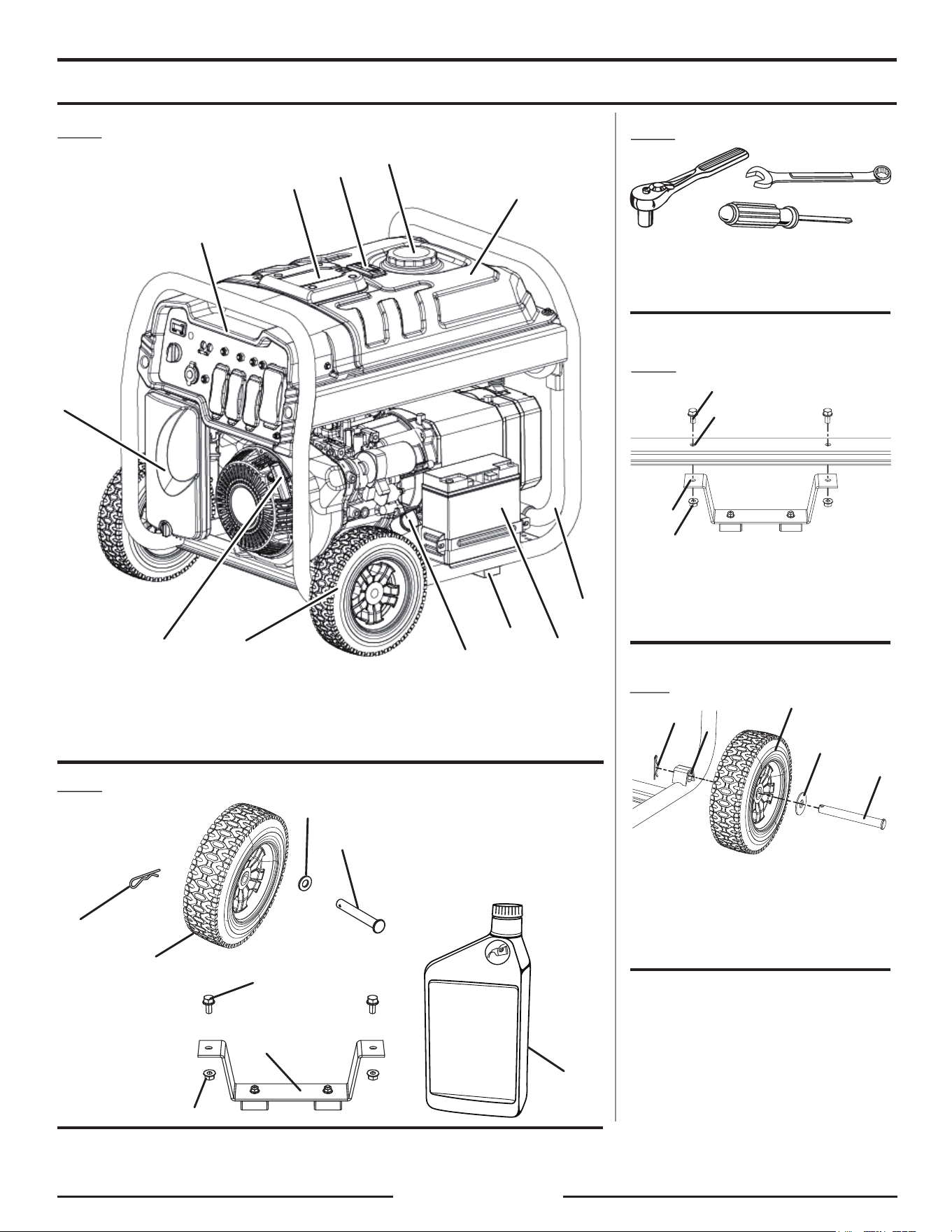
See this section for all of the figures referenced in the operator’s manual.
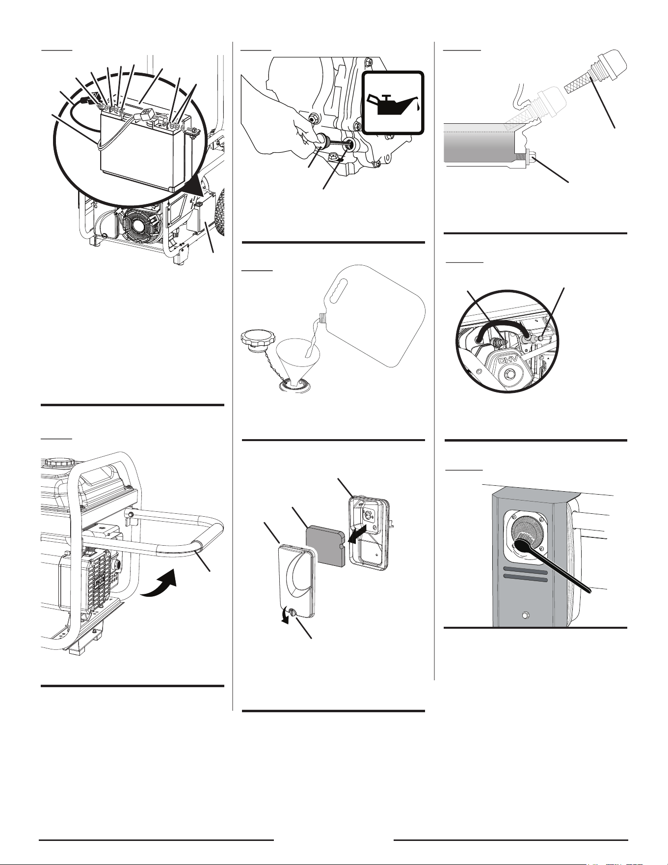
Fig. 1
A - Fuel tank / B - Fuel cap / C - Fuel Gauge / D - EFI / E - Power Panel
F - Air filter / G - Recoil starter grip / H - Wheel / I - Oil cap/dipstick
J - Foot bracket / K - Battery / L - Handle
B
A
C
D
E
F
G
H
I
K
J
L
Fig. 3
A - Socket wrench
B - Combination wrench
C - Phillips screwdriver
A
B
C
Fig.5
A - Axle
B - Wheel
C - Washer
D - Bracket
E - Hitch pin
A
B
C
D
E
A - Bolt
B - Frame
C - Foot bracket
D - Lock nut
Fig. 4
C
D
A
B
Fig. 2
8
1
2
3
4
5
7
6
Page 3 — English
A - Battery bracket
B - Positive (+) terminal
C - Negative (–) terminal
D - Black wire (–)
E - Screw
F - Washer
G - Nut
H - Red wires (+)
I - Negative terminal connection
J - Positive terminal connections
Fig. 6
A
A
C
I
G
D
B
H
E
F
J
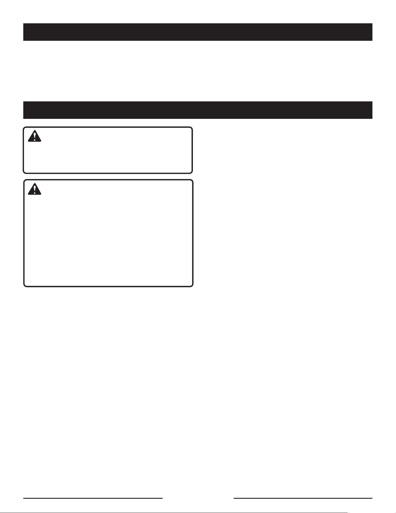
Fig. 13
Fig. 12
A - Spark plug
B - Spark plug cap
A
B
Fig. 9
A - Fuel cap
B - Fuel tank
Unleaded
Gasoline
Fig. 10
A - Knob
B - Air filter cover
C - Filter element
D - Air filter unit
A
D
B
C
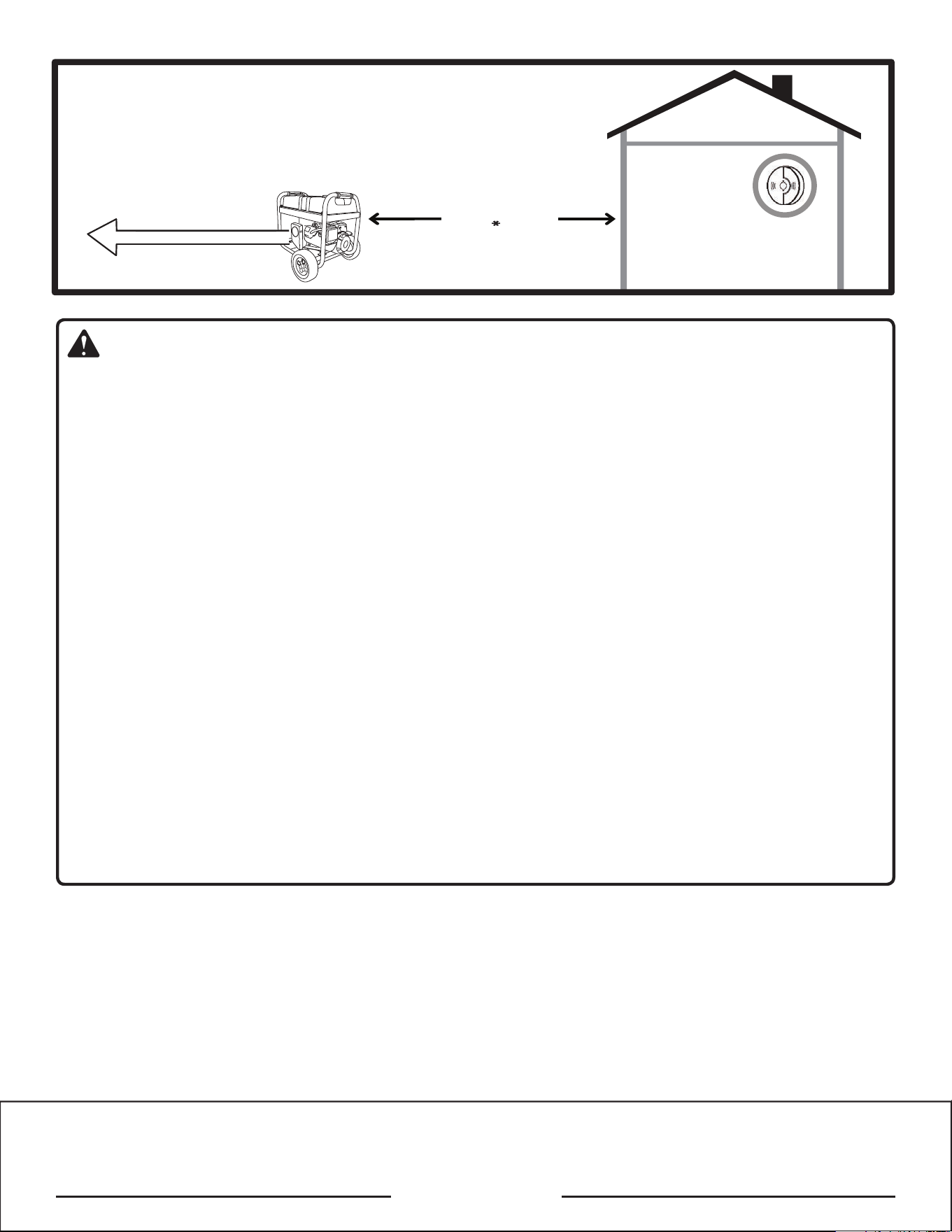
Fig. 11
A - Oil drain plug
B - Oil cap/dipstick
B
A
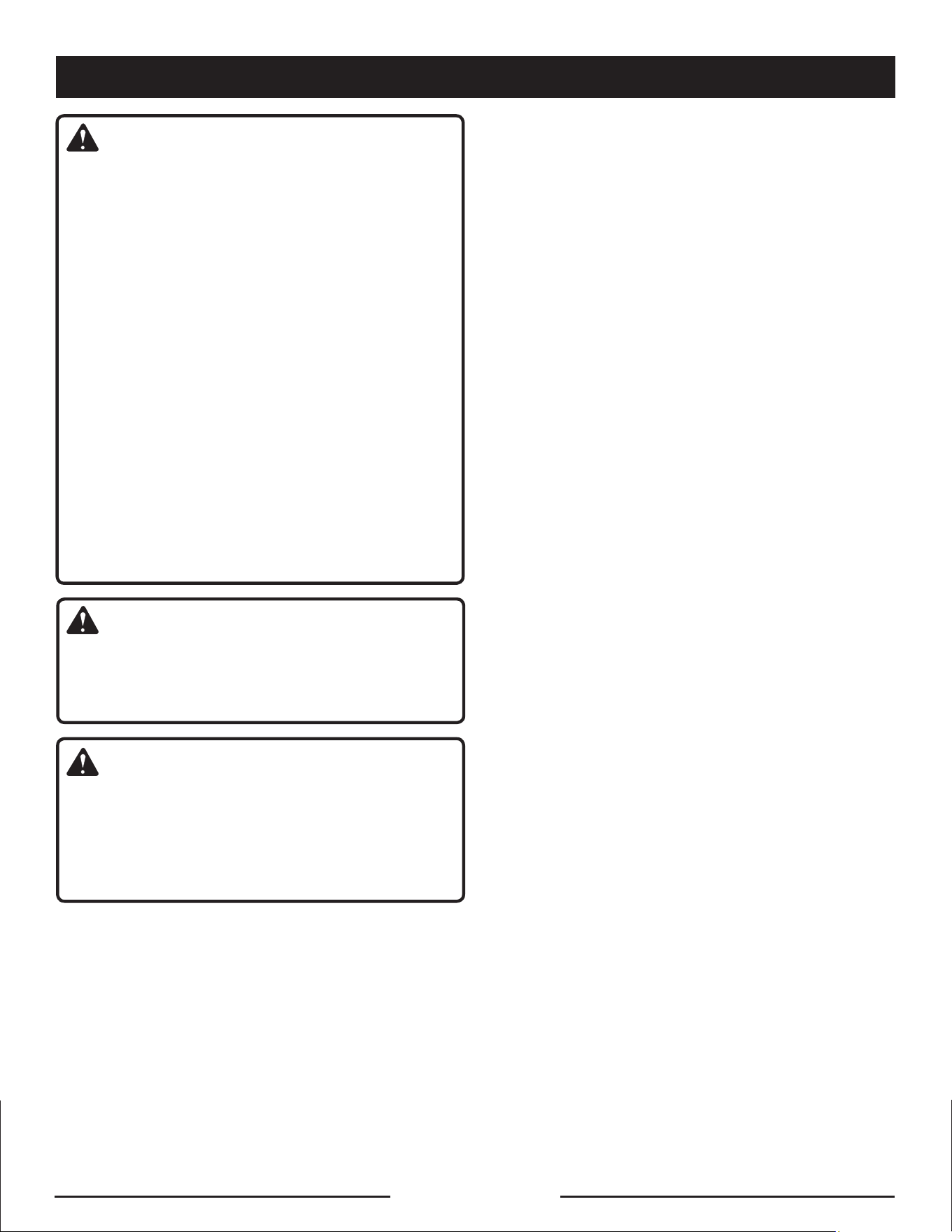
A - Oil cap/dipstick
B - Oil fill hole
Fig. 8
A
B
A - Handle
Fig. 7
A
Page 4 — English
Page 5 — English
KEEP AT LEAST
20 FT. AWAY
CO Detector
in Living Areas
Only use OUTSIDE and
FAR AWAY from windows,
doors, and vents.
Exhaust (CO)
Direct exhaust AWAY
from all windows, doors,
and vents.
LOCATE GENERATOR AT LEAST 20 FT.* AWAY TO REDUCE THE
RISK OF CARBON MONOXIDE GETTING INSIDE THE HOME
* Your specific home and/or wind conditions may require additional distance.
WARNING:
GROUNDING THE GENERATOR
If this generator will be used only with cord and plug-connected equipment, National Electric Code does not require
that the unit be grounded. However, other methods of using the generator may require grounding to reduce the risk
of shock or electrocution. Consulta qualified electrician, electrical inspector, or local agency having jurisdiction for
local codes or ordinances to find out if grounding is needed in your situation before using the generator.
When grounding is required, the nut and ground terminal on the frame are used to connect the generator to a suitable
ground source.The ground path should be made with #8 size wire. Connect the terminal of the ground wire between
the lock washer and the nut, and tighten the nut fully. Connect the other end of the wire securely to a suitable ground
source that is in contact with the soil for a minimum distance of 8 ft.
The National Electric Code contains several practical ways in which to establish a good ground source. If a steel or
iron rod is used, it should be at least 5/8 in. diameter, and if a nonferrous rod is used, it should be at least 1/2 in.
diameter and be listed as material for grounding. If a rock bottom is encountered before reaching a depth of 8 ft.,
drive the ground rod in at an angle of up to 45°. If the rock bottom is again encountered, the rod can be buried in a
trench that is at least 30 in. deep. In all cases, the upper end of the grounding rod should either be flush with (or
below) the ground or must be otherwise protected from physical damage.
All electrical tools and appliances operated from this generator must be properly grounded by use of a third wire or
be “Double Insulated.”
It is recommended to:
1. Use electrical devices with 3-prong grounded plugs.
2. Use an extension cord intended for outdoor use with a 3-pole receptacle and a 3-prong plug at opposite ends to
ensure continuity of the ground protection from the generator to the appliance.
Check and adhere to all applicable federal, state, and local regulations relating to grounding specifications. Consult a
qualified electrician or service personnel if the grounding instructions are not completely understood or if in doubt as
to whether the generator is properly grounded.
Page 6 — English
DANGER:
Carbon Monoxide. Using a generator indoors CAN KILL
YOU IN MINUTES.
Generator exhaust contains high levels of carbon mon-
oxide (CO), a poisonous gas you cannot see or smell. If
you can smell the generator exhaust, you are breathing
CO. But even if you cannot smell the exhaust, you could
be breathing CO.
Never use a generator inside homes, garages, crawl-
spaces, or other partly enclosed areas. Deadly levels
of carbon monoxide can build up in these areas. Us-
ing a fan or opening windows and doors does NOT
supply enough fresh air.
ONLY use a generator outdoors and far away from
open windows, doors, and vents. These openings
can pull in generator exhaust.
Even when you use a generator correctly, CO may
leak into the home. ALWAYS use a battery-powered or
battery-backup CO alarm in the home.
If you start to feel sick, dizzy, or weak after the generator
has been running, move to fresh air RIGHT AWAY. See
a doctor. You could have carbon monoxide poisoning.
WARNING:
Read and understand all instructions. Failure to follow
all instructions listed below could result in electrocution,
fire, and/or carbon monoxide poisoning, which can cause
death or serious injury.
WARNING:
In some applications, National Electric Code requires
generator to be grounded to an approved earth ground.
Before using the ground terminal, consult a qualified
electrician, electrical inspector, or local agency having
jurisdiction for local codes or ordinances that apply to
the intended use of the generator.
SAVE THESE INSTRUCTIONS
This manual contains important instructions that should be
followed during installation and maintenance of the generator.
Do not connect to a building’s electrical system unless
the generator and transfer switch have been properly
installed and the electrical output has been verified by
a qualified electrician.
The connection must isolate the
generator power from utility power and must comply with
all applicable laws and electrical codes.
Do not allow children or untrained individuals to use this
unit.
Do not start or operate the engine in a confined space,
building, near open windows, or in other unventilated space
where dangerous carbon monoxide fumes can collect.
Carbon monoxide, a colorless, odorless, and extremely
dangerous gas, can cause unconsciousness or death.
.yawa teef 01 tsael ta step dna ,nerd
lihc ,srednatsyb lla peeK
Wear
sturdy and dry shoes or boots. Do not operate while
barefoot.
Do not operate generator when you are tired or under the
influence of drugs, alcohol, or medication.
Keep all parts of your body away from any moving parts
and all hot surfaces of the unit.
Do not touch bare wire or receptacles.
Do not use generator with electrical cords which are worn,
frayed, bare, or otherwise damaged.
Before storing, allow the engine to cool for 30 minutes
and drain fuel from the unit.
Do not operate or store the generator in rain, snow, or
wet weather.
Store the generator in a well-ventilated area with the fuel
tank empty. Fuel should not be stored near the generator.
Empty fuel tank, close fuel valve, and restrain the unit
from moving before transporting in a vehicle.
Provide a plastic sheet or absorbent pad below the
generator to catch any drips of fuel or lubricant when
transporting.
To reduce the risk of fire and burn injury, handle fuel with
care. It is highly flammable.
Do not smoke while handling fuel.
Store fuel in a container approved for gasoline.
Position the unit on level ground, stop engine, and allow
to cool for five minutes before refueling.
Loosen
fuel
cap slowly to release pressure and to keep
fuel from escaping around the cap.
Tighten the fuel cap securely after refueling.
Wipe spilled fuel from the unit.
Never attempt to burn off spilled fuel under any circum-
stances.
Generators vibrate in normal use. During and after the
use of the generator, inspect the generator as well as
extension cords and power supply cords connected to
it for damage resulting from vibration. Have damaged
items repaired or replaced as necessary. Do not use plugs
or cords that show signs of damage such as broken or
cracked insulation or damaged blades.
For power outages, permanently installed stationary gen-
erators are better suited for providing back-up power to
the home. Even a properly connected portable generator
can become overloaded. This may result in overheating
or stressing the generator components, possibly leading
to generator failure.
IMPORTANT SAFETY INSTRUCTIONS
Page 7 — English
Use only recommended or equivalent replacement parts
and accessories and follow instructions in the Maintenance
section of this manual. Use of any other parts or failure
to follow maintenance instructions may create a risk of
shock or injury.
Maintain the unit per maintenance instructions in this
Operator’s Manual.
Inspect the unit before each use for loose fasteners, fuel
leaks, etc. Replace damaged parts.
DANGER:
Risk of fire and serious burns: Never remove fuel cap
when unit is running. Shut off engine and allow the unit
to cool at least five minutes. Remove cap slowly.
WARNING:
When this generator is used to supply a building
wiring system: generator must be installed by a quali-
fied electrician and connected to a transfer switch as
a separately derived system in accordance with NFPA
70, National Electrical Code. The generator shall be
connected through a transfer switch that switches all
conductors other than the equipment grounding con-
ductor. The frame of the generator shall be connected to
an approved grounding electrode. Failure to isolate the
generator from power utility can result in death or injury
to electric utility workers.
Do not use this generator to provide power for emergency
medical equipment or life support devices.
This generator has a neutral bonded condition. This means
the neutral conductor is electrically connected to the
frame of the machine.
Always use a battery-powered carbon monoxide detec-
tor when running the generator. If you begin to feel sick,
dizzy, or weak while using the generator, shut it off and
get to fresh air immediately. See a doctor. You may have
carbon monoxide poisoning.
Place the generator on a flat, stable surface with a slope
of no more than 4°.
Operate out
doors in
a well-ventilated, well-lit area isolated
from working areas to avoid noise interference.
Operating the generator in wet conditions could result in
electrocution. Keep the unit dry.
Keep the generator a minimum of 3 feet away from all
types of combustible material.
Do not operate generator near hazardous material.
Do not operate generator at a gas or natural gas filling
station.
Do not touch the muffler or cylinder during or immediately
after use; they are HOT and will cause burn injury.
Do not allow the generator’s gas tank to overflow when
filling. Fill to 1 in. below the top neck of the gasoline tank
to allow for fuel expansion. Do not cover the fuel tank cap
when the engine is running. Covering the fuel tank cap
during use may cause engine failure and/or damage to
the tool.
Do not smoke when filling the generator with gasoline.
Shut down the engine and allow to cool for five minutes
before adding gasoline or lubricant to the generator.
Do not remove the lubricant dipstick or the fuel tank cap
when the engine is running.
Pay close attention to all safety labels located on the
generator.
Keep children a minimum of 10 feet away from the gen-
erator at all times.
The unit operates best in temperatures between 23°F and
104°F with a relative humidity of 90% or less.
Operating voltage and frequency requirement of all
electronic equipment
should
be checked prior to plug-
ging them into this generator. Damage may result if the
equipment is not designed to operate within a +/- 10%
voltage variation, and +/- 3 hz frequency variation from
the generator name plate ratings. To avoid damage, al-
ways have an additional load plugged into the generator
if solid state equipment (such as a television set) is used.
A power line conditioner is recommended for some solid
state applications.
When battery is not in use, keep it away from other metal
objects like paper clips, coins, keys, nails, screws, or other
small metal objects that can make a connection from one
terminal to another. Shorting the battery terminals together
may cause burns or a fire.
For outdoor use only.
Save these instructions. Refer to them frequently and use
them to instruct others who may use this product. If you loan
someone this product, loan them these instructions also.
IMPORTANT SAFETY INSTRUCTIONS
SPECIFIC SAFETY RULES
Page 8 — English
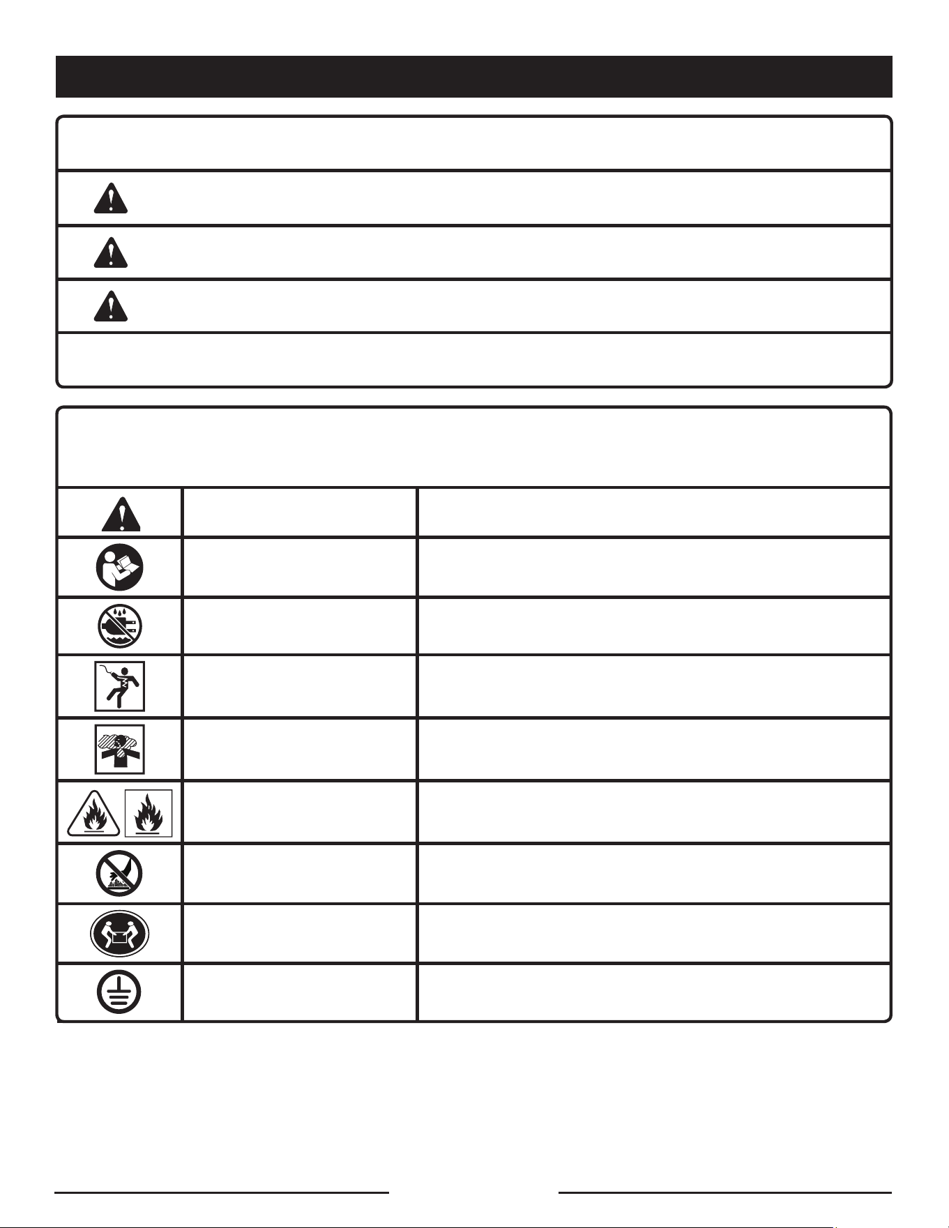
Some of the following symbols may be used on this product. Please study them and learn their meaning. Proper
interpretation of these symbols will allow you to operate the product better and safer.
SYMBOL NAME DESIGNATION/EXPLANATION
Safety Alert Indicates a potential personal injury hazard.
Read Operator’s Manual
To reduce the risk of injury, user must read and understand
operator’s manual before using this product.
Wet Conditions Alert Do not expose to rain or use in damp locations.
Electric Shock
Failure to use in dry conditions and to observe safe practices can
result in electric shock.
Toxic Fumes
Running generator gives off carbon monoxide, an odorless, color-
less, poison gas. Breathing carbon monoxide can cause nausea,
fainting, or death.
Fire/Explosion
Fuel and its vapors are extremely flammable and explosive. Fire
or explosion can cause severe burns or death.
Hot Surface and Exhaust
Gases
To reduce the risk of injury or damage, avoid contact with any
hot surface and do not place any body parts in the path of hot
exhaust gases.
Lifting Hazard
To reduce the risk of serious injury, avoid attempting to lift the
generator alone.
Ground
Consult with local electrician to determine grounding requirements
before operation.
The following signal words and meanings are intended to explain the levels of risk associated with this product.
SYMBOL SIGNAL MEANING
DANGER:
Indicates a hazardous situation, which, if not avoided, will result in death or
serious injury.
WARNING:
Indicates a hazardous situation, which, if not avoided, could result in death or
serious injury.
CAUTION:
Indicates a hazardous situation, that, if not avoided, may result in minor or
moderate injury.
NOTICE:
(Without Safety Alert Symbol) Indicates information considered important, but
not related to a potential injury (e.g. messages relating to property damage).
SYMBOLS
Page 9 — English
Some of the following symbols may be used on this product. Please study them and learn their meaning. Proper
interpretation of these symbols will allow you to operate the product better and safer.
SYMBOL NAME DESIGNATION/EXPLANATION
V Volts Voltage
A Amperes Current
Hz Hertz Frequency (cycles per second)
W Watt Power
hrs Hours Time
gal Gallon Volume
qt Quart Volume
SYMBOLS
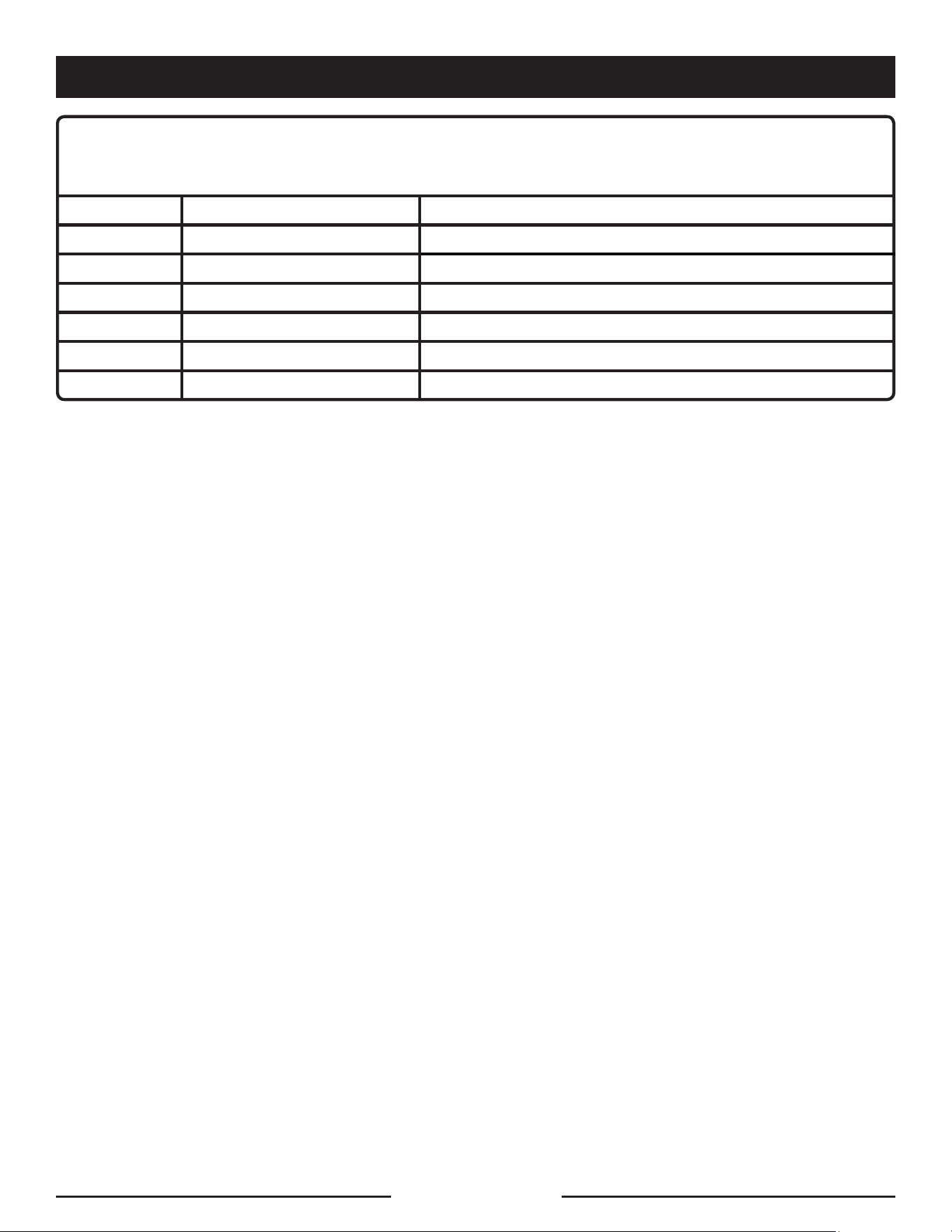
EXTENSION CORD CABLE SIZE
Refer to the table below to ensure the cable size of the extension cords you use are capable of carrying the required load.
Inadequate size cables can cause a voltage drop, which can burn out the appliance and overheat the cord.
Current in
Amperes
Load in Watts Maximum Allowable Cord Length
At 120V At 240V #8 Wire #10 Wire #12 Wire #14 Wire #16 Wire
2.5 300 600 1000 ft. 600 ft. 375 ft. 250 ft.
5 600 1200 500 ft. 300 ft. 200 ft. 125 ft.
7.5 900 1800 350 ft. 200 ft. 125 ft. 100 ft.
10 1200 2400 250 ft. 150 ft. 100 ft. 50 ft.
15 1800 3600 150 ft. 100 ft. 65 ft.
20 2400 4800 175 ft. 125 ft. 75 ft.
25 3000 6000 150 ft. 100 ft.
30 3600 7200 125 ft. 65 ft.
40 4800 9600 90 ft.
ELECTRIC MOTOR LOADS
It is characteristic of common electric motors in normal operation to draw up to six times their running current while starting.
This table may be used to estimate the watts required to start electric motors; however, if an electric motor fails to start or
reach running speed, turn off the appliance or tool immediately to avoid equipment damage. Always check the requirements
of the tool or appliance being used compared to the rated output of the generator.
Motor Size (H.P.) Running Watts
Watts Required to Start Motor
Universal Capacitor Split Phase
1/8 275 N/A 850 1200
1/6 275 600 850 2050
1/4 400 800 1050 2400
1/3 450 950 1350 2700
1/2 600 1000 1800 3600
3/4 850 1200 2600 —
1 1100 N/A 3300 —
NOTICE:
Operating voltage and frequency requirement of all electronic equipment should be checked prior to plugging them
into this generator. Damage may result if the equipment is not designed to operate within a +/- 10% voltage variation,
and +/- 3 hz frequency variation from the generator name plate ratings. To avoid damage, always have an additional
load plugged into the generator if solid state equipment (such as a television set) is used. A power line conditioner is
recommended for some solid state applications.
ELECTRICAL
Page 10 — English
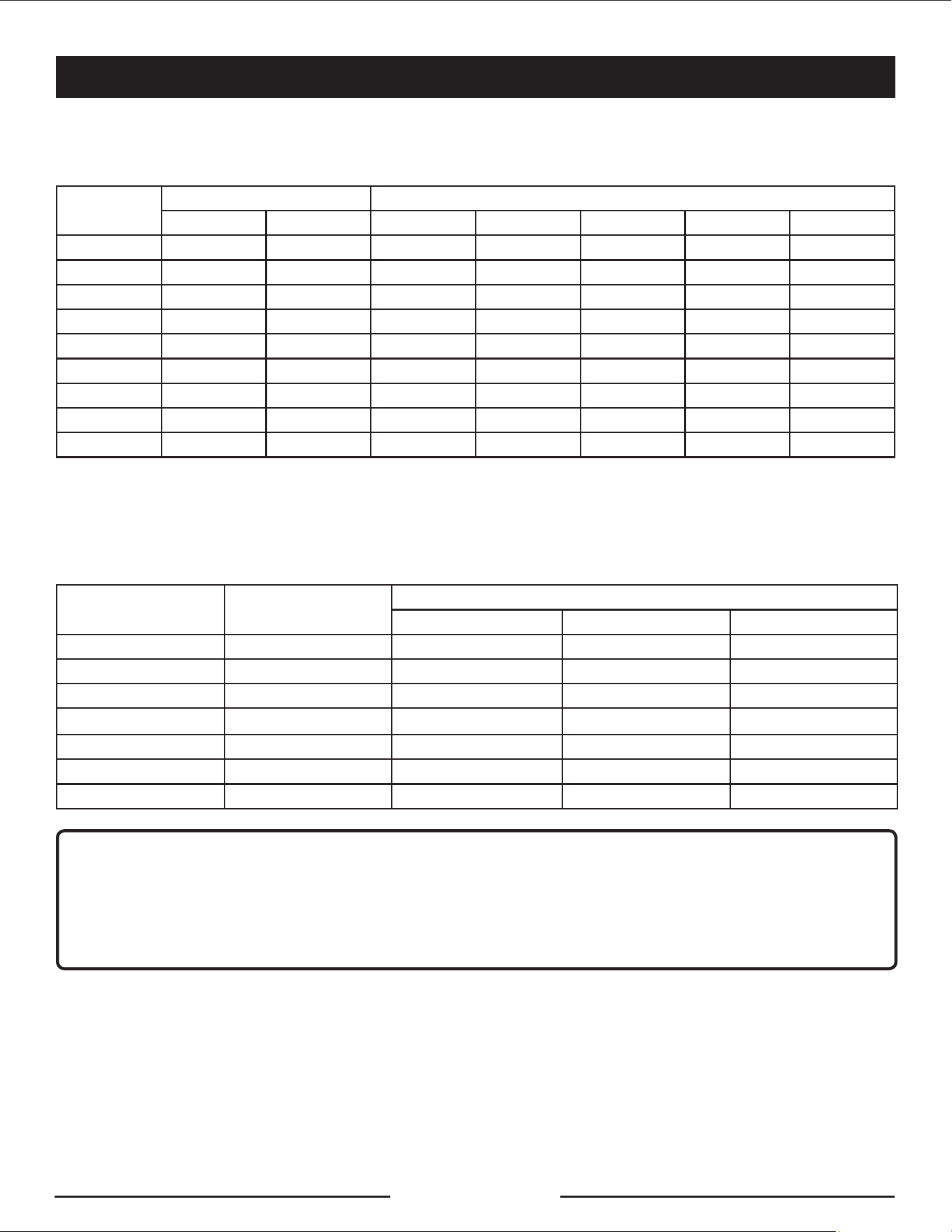
GENERATOR CAPACITY
Make sure the generator can supply enough continuous (run-
ning) and surge (starting) watts for the items you will power
at the same time. Follow these simple steps.
1. Select the items you will power at the same time.
2. Total the continuous (running) watts of these items. This
is the amount of power the generator must produce to
keep the items running. See the wattage reference chart
at right.
3. Estimate how many surge (starting) watts you will need.
Surge wattage is the short burst of power needed to
start electric motor-driven tools or appliances such as a
circular saw or refrigerator. Because not all motors start
at the same time, total surge watts can be estimated by
adding only the item(s) with the highest additional surge
watts to the total rated watts from step 2.
Example:
Tool or Appliance
Running
Watts*
Starting
Watts*
Window AC,
10,000 BTU
1200 1800
Refrigerator 700 2200
1/3 HP Well Pump 1000 2000
27 in. Television 500 0
Light (75 Watts) 75 0
3475 Total
Running Watts
2200 Highest
Starting Watts
Total Running Watts 3475
Highest Starting Watts + 2200
Total Starting Watts Needed 5675
POWER MANAGEMENT
To prolong the life of the generator and attached devices,
it is important to take care when adding electrical loads to
the generator. There should be nothing connected to the
generator outlets before starting its engine. The correct and
safe way to manage generator power is to sequentially add
loads as follows:
1. With nothing connected to the generator, start the engine
as described later in this manual.
2. Plug in and turn on the first load, preferably the largest
load you have.
3. Permit the generator output to stabilize (engine runs
smoothly and attached device operates properly).
4. Plug in and turn on the next load.
5. Again, permit the generator to stabilize.
6. Repeat steps 4 and 5 for each additional load.
Never add more loads than the generator capacity. Take
special care to consider surge loads in generator capacity
as previously described.
Application/Equipment
Estimated
Running
Watts*
Estimated
Starting
Watts*
Emergency / Home Standby
Clock Radio 50 0
Lights (qty. 4 x 75 W) 300 0
Refrigerator 700 2200
Furnace Fan 800 2350
Water Well Pump 1000 1500
Microwave 1000 1000
Sump Pump 1050 2200
Electric Range (per element) 2100 0
Job Site
Electric Drill − 1/2 HP 600 900
Airless Sprayer − 1/3 HP 600 1200
Quartz Halogen Work Light 1000 1000
Reciprocating Saw 960 1920
Air Compressor − 1 HP 1600 4500
Circular Saw − 7-1/4 in. 1400 2300
Planer/Jointer − 6 in 1800 1800
Miter Saw − 10 in. 1800 1800
Table Saw/Radial Arm Saw − 10 in. 2000 2000
*Wattages listed are approximate. Check tool or appliance for actual wattage.
NOTICE:
Do not overload the generator’s capacity. Exceeding the
generator’s wattage/amperage capacity may damage
the generator and/or electrical devices connected to it.
ELECTRICAL
Page 11 — English

KNOW YOUR GENERATOR
See Figure 1.
The safe use of this product requires an understanding of the
information on the product and in this operator’s manual as
well as a knowledge of the project you are attempting. Before
use of this product, familiarize yourself with all operating
features and safety rules.
AC CIRCUIT BREAKERS
The circuit breakers are provided to protect the generator
against electrical overload. The circuit breaker may be reset
by pressing the circuit breaker reset button.
AIR FILTER
The air filter helps to limit the amount of dirt and dust drawn
into the unit during operation.
DIGITAL DISPLAY
The digital display shows AC voltage output, frequency, how
long the engine has been running during the current usage
period, and the total number of hours the unit has been used.
ENGINE SWITCH
The engine switch is used alone or in combination with the
recoil starter grip to start the engine. It is also used to turn
the engine off.
FUEL VALVE
Fuel flow from the fuel tank to the engine is turned on and
off using the fuel valve.
GROUND TERMINAL
The ground terminal is used to assist in properly grounding
the generator to help protect against electrical shock. Consult
with a qualified local electrician for grounding requirements
in your area.
LOW OIL SHUT DOWN PROTECTOR
The low oil sensor causes the engine to stop if the level of
lubricant in the crankcase is insufficient.
OIL CAP/DIPSTICK
Remove the oil fill cap to check and add lubricant to the
generator when necessary.
OIL DRAIN PLUG
When changing the engine lubricant, unscrew and remove
the oil drain plug to allow old engine lubricant to be drained.
RECEPTACLES
These can be used for operating appropriate appliances,
electrical lighting, tools, and motor loads.
RECOIL STARTER GRIP
The recoil starter grip is used (along with the engine switch)
to start the generator’s engine.
EFI
Electronic fuel injection (EFI), an onboard electronic engine
management system that can greatly reduce CO emissions
generated by the portable generator's engine. By significantly
reducing the amount of CO a portable generator emits, the
likelihood of CO poisoning and death is greatly reduced.
CO SENSOR
The CO Sensor is able to detect the carbon monoxide. If
the CO concentration in a certain range, the CO Sensor
will immediately “bleep” and the light will blink; If the
concentration in a high range, the CO Sensor will shut the
generator off.
FEATURES
UNPACKING
This product requires assembly.
Carefully cut the box down the sides then remove the
machine and any accessories from the box. Make sure
that all items listed in the loose parts list are included.
NOTE: This machine is heavy and requires a minimum of
two people to lift. To avoid back injury, lift with your legs
and not your back.
WARNING:
Do not use this product if any parts in the Loose Parts List
are already assembled to your product when you unpack
it. Parts on this list are not assembled to the product by
the manufacturer and require customer installation. Use
of a product that may have been improperly assembled
could result in serious personal injury.
Inspect the unit carefully to make sure no damage oc-
curred during shipping.
Do not discard the packing material until you have carefully
inspected and satisfactorily operated the product.
ASSEMBLY
Page 12 — English
WARNING:
If any parts are damaged or missing do not operate
this product until the parts are replaced. Use of this
product with damaged or missing parts could result in
serious personal injury.
WARNING:
Do not attempt to modify this product or create acces-
sories not recommended for use with this product. Any
such alteration or modification is misuse and could result
in a hazardous condition leading to possible serious per-
sonal injury.
WARNING:
Do not attempt to operate the generator until assembly
is complete. Failure to comply could result in possible
serious personal injury.
LOOSE PARTS LIST
See Figure 2.
The following items are included with the generator:
Key
No. Description Qty.
1 Wheel ...................................................................2
2 Axle ......................................................................2
3 Washer .................................................................2
4 Hitch Pin ..............................................................2
5 Bolt ......................................................................2
6 Foot Bracket ........................................................1
7
8
Lock Nut .............................................................2
Engine Lubricant..................................................1
Operator’s Manual (not shown) ...........................1
TOOLS NEEDED
See Figure 3.
The following tools (not included or drawn to scale) are
needed for assembly:
Socket Wrenches and/or Combination Wrenches
Philips Screwdriver
NOTE: Do not put fuel or lubricant in the generator before
installing the feet, frame support, wheels and handle.
INSTALLING THE FEET
See Figure 4.
Locate the following items:
Foot bracket
2 lock nuts
2 bolts
Insert bolts through the foot bracket and holes in
the generator frame as shown.
Thread lock nuts onto bolts and tighten one full turn past
snug.
NOTE: Be careful not to overtighten so that foot mate-
rial collapses.
ASSEMBLY
WARNING:
Keep metal objects away from the battery terminals.
Metal objects can make a connection from one terminal
to another. Shorting the battery terminals together can
cause sparks, burns, or a fire.
INSTALLING THE WHEELS
See Figure 5.
Wheels are provided to assist in moving the generator to
the desired location and should be installed on the same
side as the handle.
Locate the following items:
2 axles
2 hitch pins
2 washers
2 wheels
Raise the end of the generator where the handle is located
high enough to gain access to the frame bottom; securely
position props underneath to support.
Slide the axle through the hole in the center of the wheel.
Slide a washer onto the axle, then slide the axle into the
wheel mounting hole as shown.
Insert hitch pin to secure.
NOTE: The hitch pin should be pushed into the axle until
the center of the pin rests on top of the axle.
Repeat with the second wheel.
CONNECTING/DISCONNECTING BATTERY
See Figure 6.
WARNING:
To reduce the risk of electrocution or explosion, do not
short circuit the battery terminals or charge in a sealed
container. Keep sparks and flame away.
Page 13 — English
Page 14 — English
ASSEMBLY
NOTICE:
The battery may require charging before the generator
can be started using either the engine switch or the recoil
starter. Once the generator is started, the battery will
charge as the unit runs.
The battery cables must be connected before the generator
can be operated.
To connect battery cables:
Connect the red wires to the positive (+) terminal first,
then connect the black wire to the negative (-) terminal.
Make sure all connections are tight.
NOTE: Be careful not to short across the terminals when
installing. Shorting the terminals together can cause
sparks, damage to the battery or generator, or even burns
or explosions.
Cover the terminals with the rubber covers.
When removing the battery for replacement: disconnect
the negative (black) post, then the positive (red) post, being
careful not to short across the terminals. Always abide by the
safety warnings provided with the battery. Remove the battery
and dispose of according to local and state regulations.
OPERATION
DANGER:
Carbon Monoxide. Using a generator indoors CAN KILL YOU IN MINUTES.
Generator exhaust contains high levels of carbon monoxide (CO), a poisonous gas you cannot see or smell. If you can
smell the generator exhaust, you are breathing CO. But even if you cannot smell the exhaust, you could be breathing CO.
Never use a generator inside homes, garages, crawlspaces, or other partly enclosed areas. Deadly levels of carbon
monoxide can build up in these areas. Using a fan or opening windows and doors does NOT supply enough fresh
air.
ONLY use a generator outdoors and far away from open windows, doors, and vents. These openings can pull in
generator exhaust.
Even when you use a generator correctly, CO may leak into the home. ALWAYS use a battery-powered or battery-backup
CO alarm in the home.
If you start to feel sick, dizzy, or weak after the generator has been running, move to fresh air RIGHT AWAY. See a doc-
tor. You could have carbon monoxide poisoning.
WARNING:
If this generator will be used only with cord and plug-
connected equipment, National Electric Code does
not require that the unit be grounded. However, other
methods of using the generator may require grounding
to reduce the risk of shock or electrocution. Consult a
qualified electrician, electrical inspector, or local agency
having jurisdiction for local codes or ordinances to find
out if grounding is needed in your situation before using
the generator.
WARNING:
Do not allow familiarity with this product to make you
careless. Remember that a careless fraction of a second
is sufficient to inflict serious injury.
WARNING:
Do not use any attachments or accessories not
recommended by the manufacturer of this product. The
use of attachments or accessories not recommended
can result in serious personal injury.
NOTICE:
This product is equipped with a spark arrestor that has
been evaluated by the USDA Forest Service; however,
product users must comply with Federal, State, and local
fire prevention regulations. Check with appropriate au-
thorities. Contact customer service or a qualified service
center to purchase a replacement spark arrestor.
Page 15 — English
If level is low, add engine lubricant until the fluid level rises
to the upper portion of the dipstick.
Replace and secure the oil cap/dipstick.
USING FUEL STABILIZER
Fuel gets old, oxidizes, and breaks down over time. Adding
a fuel stabilizer (not included) extends the usable life of fuel
and helps prevent deposits from forming that can clog the
fuel system. Follow fuel stabilizer manufacturer’s directions
for correct ratio of stabilizer to fuel.
Mix fuel stabilizer and gasoline prior to filling the tank
by using a gas can or other approved fuel container and
shaking gently to combine.
NOTE: To control the amount of fuel stabilizer being added
to the engine, always mix fuel stabilizer with gasoline
before fueling the tank rather than adding fuel stabilizer
directly into the generator’s fuel tank.
Replace and secure the fuel tank cap.
Start and run the engine for at least 5 minutes to allow
stabilizer to treat the entire fuel system.
ETHANOL-BLENDED FUELS
NOTICE:
Do not use E15 or E85 fuel in this product. It is a viola-
tion of federal law and will damage the unit and void
your warranty. Only use unleaded gasoline containing
up to 10% ethanol.
NOTICE:
Before each use, inspect the entire product for damaged,
missing, or loose parts such as screws, nuts, bolts,
caps, etc. Tighten securely all fasteners and caps and
do not operate this product until all missing or damaged
parts are replaced. Please contact customer service or
a qualified service center for assistance.
APPLICATIONS
This generator is designed to supply electrical power for
operating compatible electrical lighting, appliances, tools,
and motor loads.
BEFORE OPERATING THE UNIT
Only use OUTSIDE and at least 20 feet away from win-
dows, doors, and vents as recommended by the U.S
Department of Health and Human Services Centers for
Disease Control and Prevention. Your specific home and/
or wind conditions may require additional distance.
OPERATION
NOTE: If a separate engine manual is provided for this
product, please follow the instructions provided in the
engine manual instead of the information listed below.
Engine lubricant has a major influence on engine performance
and service life. For general, all-temperature use, SAE 10W-
30 full synthetic is recommended. Always use a 4-stroke
motor lubricant that meets or exceeds the requirements for
API service classification SJ.
This engine comes with a feature that will shut off the engine
when a specific lubricant level is not maintained. The engine
will not restart until an appropriate lubricant level is reached.
NOTE: Non-detergent or 2-stroke engine lubricants will
damage the engine and should not be used.
Unscrew the oil cap/dipstick and remove.
Wipe dipstick clean and re-seat in hole; do not re-thread.
Remove dipstick again and check lubricant level. Lubri-
cant level should fall between the hatched areas on the
dipstick.
NEVER use inside a home or garage, EVEN IF doors and
windows are open.
Always position the generator on a flat firm surface.
SPECIAL REQUIREMENTS:
There may be General or State Occupational Safety and
Health Administration (OSHA) regulations, local codes or
.rotareneg eht fo esu ded
netni eht ot ylppa taht secnanidro
Please
consult a qualified electrician, electrical inspector, or
the local agency having jurisdiction:
In some areas, generators are required to be registered
with local utility companies.
If the generator is used at a construction site, there may
be additional regulations which must be observed.
RAISING AND LOWERING THE HANDLE
See Figure 7.
To raise the handle (for moving the generator)
To lower the handle (for storing or transporting the
generator)
Never use the handle to lift the generator. The handle should
only be used for moving the unit by rolling it on its wheels.
CHECKING/ADDING LUBRICANT
See Figure 8.
NOTICE:
Attempting to start the engine before it has been properly
filled with lubricant will result in equipment failure.
When a cumulative run time of 25 hours has been reached,
P25 will display on the meter as a reminder to change the
engine lubricant after the initial 25 hours of run time.
When a cumulative time of 50 hours is reached, P50 will
display on the meter to remind you to clean the air filter.
When a cumulative time of 100 hours is reached, P100 will
display on the meter to remind you to change/clean the fuel
filter, clean the air filter, and change the engine lubricant.
ELECTRIC START
This generator model is provided with both electric start and
recoil start capabilities. Avoid prolonged cranking, as it can
damage the engine.
The battery provided is a nominal 12 volt sealed rechargeable
lead-acid battery and can be operated in any position without
leakage. It complies with non-spillable battery regulations.
NOTE: Brand new generators are shipped with the battery
connections disconnected. The positive and negative
terminals must be connected to the battery before the Electric
Start feature will work.
For initial battery connection, see Connecting/Disconnecting
Battery.
OPERATION
ADDING FUEL
See Figure 9.
DANGER:
Risk of fire and serious burns: Never remove fuel cap
when unit is running. Shut off engine and allow the unit
to cool at least five minutes. Remove cap slowly.
WARNING:
Gasoline and its vapors are highly flammable and ex-
plosive. To prevent serious personal injury and property
damage, handle gasoline with care. Keep away from igni-
tion sources, handle outdoors only, do not smoke while
adding fuel, and wipe up spills immediately.
When adding gas to the generator, make sure the unit is sitting
on a flat, level surface. If the engine is hot, let the generator
cool for five minutes before adding gas. ALWAYS fill the fuel
tank outdoors with the machine turned off.
Remove the fuel cap slowly.
Fill the fuel tank to 1 in. below the top of the fuel neck.
Replace and secure the fuel cap.
WARNING:
Always shut off engine before fueling. Never remove
fuel cap or add fuel to a machine with a running or hot
engine. Make sure the unit is sitting on a flat, level sur-
face and only add fuel outdoors. If the engine is hot, let
the unit cool for at least five minutes before adding fuel.
After fueling, immediately replace fuel cap and tighten
securely. Move at least 30 ft. from refueling site before
starting engine. Do not smoke and stay away from open
flames and sparks! Failure to follow these instructions
could result in a fire and cause serious personal injury.
NOTE: Always use unleaded gasoline with a pump octane
rating of 86 or higher. Never use old, stale, or contaminated
gasoline, and do not use a lubricant/gas mixture. Do not
allow dirt or water into the fuel tank. Do not use E85 fuel.
DIGITAL DISPLAY
Press and release the mode button to cycle through the
following displays:
Voltage (V) displays the operating voltage of the generator.
Frequency (F) displays the frequency in hertz at which the
generator is running.
The Run/Maintenance Timer displays the amount of time
the generator has run since being started. This timer resets
each time the generator is shut off.
Page 16 — English
STARTING THE ENGINE
NOTICE:
On a level surface with the engine off, check the lubricant
level before each use of the generator.
NOTE: If location of generator is not level, the unit may not
start or may shut down during operation.
This generator is equipped with electronic fuel injection.
Starting the generator will require a brief wait to allow the
fuel to travel from the tank.
Unplug all loads from the generator.
To start the engine using the electric start:
1
Put the engine switch in the ON position.
2
Wait 30 seconds to allow fuel to travel through the
line.
NOTE: The engine will not start until the fuel has
reached the fuel injector and the proper operating
pressure is acheived.
3
Turn and hold the engine switch to the START
position. Do not hold the engine switch in START
position for more than 15 seconds. Allow 1 minute
between starting attempts.
NOTE: The battery may require charging before the gen-
erator can be started using either the engine switch or the
recoil starter. Once the generator is started, the battery will
charge as the unit runs.
Page 17 — English
To start the engine using the recoil starter:
1
Put the engine switch in the ON position.
2
Wait 30 seconds to allow fuel to travel through the
line.
NOTE: The engine will not start until the fuel has
reached the fuel injector and the proper operating
pressure is acheived.
3
Pull the recoil starter grip until the engine runs.
NOTE: Do not allow the grip to snap back after starting;
return it gently to its original place.
STOPPING THE ENGINE
To stop the engine under normal operating conditions:
Remove any load from the generator.
Turn the engine switch to the OFF position.
WARNING:
While operating and storing, keep at least 3 feet of clear-
ance on all sides of this product, including overhead.
Allow a minimum of 30 minutes of “cool down” time
before storage. Heat created by muffler and exhaust
gases could be hot enough to cause serious burns and/
or ignite combustible objects.
OPERATION
MAINTENANCE
Normal maintenance, replacement or repair of emission con-
trol devices and systems may be performed by any qualified
repair establishment or individual with original or equivalent
parts. Warranty and recall repairs must be performed by an
authorized service center; please contact customer service
for assistance.
WARNING:
Before inspecting, cleaning, or servicing the machine,
shut off engine, wait for all moving parts to stop, and
disconnect spark plug wire and move it away from spark
plug. Allow 30 minutes of cool down time before perform-
ing any maintenance. Failure to follow these instructions
can result in serious personal injury or property damage.
WARNING:
When servicing, use only recommended or equivalent
replacement parts. Service or maintenance performed
by unqualified personnel or use of any other parts could
result in a personal injury hazard or property damage.
NOTICE:
Periodically inspect the entire product for damaged,
missing, or loose parts such as screws, nuts, bolts,
caps, etc. Tighten securely all fasteners and caps and
do not operate this product until all missing or damaged
parts are replaced. Please contact customer service or
a qualifed service center for assistance.
GENERAL MAINTENANCE
Keep the generator in a clean and dry environment where it
is not exposed to dust, dirt, moisture, or corrosive vapors.
Do not allow the cooling air slots in the generator to become
clogged with foreign material such as leaves, etc.
Do not use a garden hose to clean the generator. Water en-
tering the fuel system or other internal parts of the unit can
cause problems that will decrease the life of the generator.
To clean the unit:
Use a soft bristle brush and/or vacuum cleaner to loosen
and remove dirt and debris.
Clean air vents with low pressure air that does not exceed
25 psi.
Wipe the exterior surfaces of the generator with a damp
cloth.
CHECKING/CLEANING AIR FILTER
See Figure 10.
For proper performance and long life, keep air filter clean.
Turn the knob on the bottom of air the filter cover to re-
lease. Remove cover and set aside.
Remove the filter element.
If the filter element is dirty, clean with warm, soapy water.
Rinse and let dry.
Apply a light coat of engine lubricant to the element, then
squeeze it out.
Replace the element in the air filter unit.
Replace the air filter cover and latch to secure.
NOTE: Do not run the generator without the air filter. Rapid
engine wear will result.
Page 18 — English
CHANGING ENGINE LUBRICANT
See Figure 11.
Remove the oil cap/dipstick.
Place a container underneath the oil drain plug to collect
used lubricant as it drains.
Unscrew the oil drain plug and remove.
Allow lubricant to drain completely.
NOTE: Drain the lubricant while the engine is still warm
but not hot. Warm lubricant will drain quickly and more
completely.
WARNING:
Do not change engine lubricant while it is hot. Accidental
contact with hot engine lubricant could result in serious burns.
Reinstall the oil drain plug and tighten securely.
Refill with lubricant following the instructions in the Checking/
Adding Lubricant section. For amount of lubricant needed
to refill, see Product Specifications earlier in this manual
or the accompanying engine manual, if applicable.
Reinstall the oil cap/dipstick.
NOTE: Used lubricant should be disposed of at an approved
disposal site. See your local oil retailer for more information.
SPARK PLUG MAINTENANCE
See Figure 12.
The spark plug must be properly gapped and free of deposits
in order to ensure proper engine operation. To check:
Remove the spark plug cap.
Clean any dirt from around base of spark plug.
Remove spark plug using wrench (not included).
Inspect spark plug for damage, and clean with a wire
brush before reinstalling. If insulator is cracked or
chipped, spark plug should be replaced. For replacement
spark plug, see Product Specifications earlier
in
this
manual or the accompanying engine manual, if applicable.
Measure plug gap. The correct gap is 0.028−0.031 in.
(0.7-0.8 mm). To widen gap, if necessary, carefully bend
the ground (top) electrode. To lessen gap, gently tap
ground electrode on a hard surface.
Seat spark plug in position; thread in by hand to prevent
cross-threading.
Tighten with wrench to compress washer. If spark plug
is new, use 1/2 turn to compress washer appropriate
amount. If reusing old spark plug, use 1/8 to 1/4 turn for
proper washer compression.
NOTE An improperly tightened spark plug will become
very hot and could damage the engine.
Reinstall the spark plug cap.
CLEANING THE EXHAUST PORT AND
MUFFLER
Depending on the type of fuel used, the type and amount of
lubricant used, and/or your operating conditions, the exhaust
port and muffler may become blocked with carbon deposits.
If you notice a power loss with your gas-powered products,
you may need to remove these deposits to restore perfor-
mance. We highly recommend that only qualified service
technicians perform this service.
SPARK ARRESTOR
See Figure 13.
NOTICE:
This product is equipped with a spark arrestor that has
been evaluated by the USDA Forest Service; however,
product users must comply with Federal, State, and local
fire prevention regulations. Check with appropriate au-
thorities. Contact customer service or a qualified service
center to purchase a replacement spark arrestor.
MAINTENANCE
Inspect the spark arrestor for breaks or holes. Clean or
replace if necessary.
Use a brush (not provided) to remove carbon deposits from
the spark arrestor screen as needed.
TRANSPORTING
Turn the engine switch OFF ( O ).
Disconnect any equipment that is plugged into the generator.
Verify the fuel valve is in the OFF ( O ) position.
Allow 30 minutes of “cool down” time before storing the
machine. Make sure engine and exhaust of unit are cool.
For security, insert the pins to secure the handles before
transporting.
Tilt the machine toward you until it balances on the wheels,
then roll the machine to the desired location.
If transporting in a vehicle, drain the fuel tank, close fuel
valve, and securely restrain the generator.
Provide a plastic sheet or absorbent pad below the generator
to catch any drips of fuel or lubricant.

Page 19 — English
STORAGE
When preparing the generator for storage, allow the unit to cool for 30 minutes then follow the guidelines below.
STORAGE TIME PRIOR TO STORING
Less than 2 months Drain gasoline from tank and dispose of in a suitable container according to state and local ordinances.
2 months to 1 year Drain gasoline from tank and dispose of in a suitable container according to state and local ordinances.
1 year or more Remove spark plug.
Drain gasoline from tank and dispose of in a suitable container according to state and local ordinances.
Put a tablespoon of engine lubricant into the spark plug cylinder. Turn the engine slowly with the pull
rope to distribute the lubricant.
Reinstall spark plug.
Change engine lubricant.
After removal from storage:
Fill with fresh gasoline.
NOTE: If storing gasoline in suitable container for later use, make sure gasoline has been treated with fuel stabilizer
according to stabilizer manufacturer’s instructions.
MAINTENANCE
MAINTENANCE SCHEDULE
NOTE: If a separate engine manual is provided for this generator, please follow the maintenance schedule provided in the engine
manual instead of the maintenance information listed below.
Before
each
use
After 1st
month or
25 hours of
operation
Every 100
hours of
operation
Every 200
hours of
operation
Every 240
hours of
operation
Every 300
hours of
operation
Every 400
hours of
operation
Every 480
hours of
operation
Every 500
hours of
operation
Check Engine
Lubricant
Change Engine
Lubricant
2
Check Air Filter
Change Air
Filter
2
Check/Adjust
Spark Plug
Replace Spark
Plug
2
Check/Clean
Spark Screen
Check/Adjust
Idle Speed
Check/
Adjust Valve
Clearance
1,2
Check/Adjust
Head Bolt
Torque
1,2
Fuel Filter Inspect Replace
1. These items should only be carried out by a qualified service center.
2. See engine manual for maintenance schedule for this item.
NOTE: Maintenance should be performed more frequently when generator is used in dusty areas.
When generator has exceeded the maximum figures specified in the table, maintenance should still be cycled according to
the intervals of time or hours stated herein.

Page 20 — English
PROBLEM POSSIBLE CAUSE SOLUTION
Engine will not start. Battery not charged.
Engine switch is OFF.
No fuel.
Stale gasoline or water in gasoline.
Lubricant level is low.
Fuel valve is OFF.
Spark plug faulty, fouled, or improperly
gapped.
Engine stored without treating or
draining gasoline, or refueled with bad
gasoline.
Dirty fuel filter.
Charge battery.
Turn engine switch to ON.
Fill fuel tank.
Drain entire system and refill with fresh
fuel.
Engine is equipped with Low Oil Shutoff.
If engine lubricant level is low, it must be
filled before unit will start. Check engine
lubrincant level and fill, if necessary.
Turn fuel valve ON.
Replace spark plug.
Drain fuel. Refuel with fresh gasoline.
Replace fuel filter or contact a qualified
service center.
Engine hard to start. Water in gasoline.
Weak spark at spark plug.
Drain entire system and refill with fresh
fuel.
Replace spark plug or contact a quali-
fied service center.
Engine lacks power. Dirty air filter.
Engine stored without treating or
draining gasoline, or refueled with bad
gasoline.
Check air filter element. Clean or replace
as needed.
Drain fuel. Refuel with fresh gasoline. If
problem continues, contact a qualified
service center.
Electric start feature not working. Battery wires are disconnected.
Battery is not charged.
Connect the battery wires.
Charge the battery.
AC receptacle does not work. Circuit breaker is tripped.
GFCI is tripped.
Item plugged in is defective.
Reset the AC circuit breaker.
Reset the GFCI.
Try a different item.
Generator
makes a
“spark knock” or
“pinging” noise.
An occasional light “knocking” or “ping-
ing” under heavy load is not a cause for
concern. However, if the knocking or
pinging occurs under normal load at a
steady engine speed, the problem may
be with the brand of gasoline being used.
Switch to a different brand of gasoline,
making sure that the octane rating is 86
or higher. If problem continues, contact
a qualified service center.
If problem persists after trying the above solutions, contact customer service or a qualified service center for assistance.
NOTICE:
As the equipment owner, you are responsible for the performance of the required maintenance listed in the Maintenance
section. It is recommended that you retain all receipts covering maintenance on your equipment. Neglecting or failing
to perform the required maintenance may increase emissions, decrease fuel efficiency, degrade performance, cause ir-
reversible engine damage and/or void your warranty.
TROUBLESHOOTING

Page 21 — English
WARRANTY
CALIFORNIA EMISSION CONTROL WARRANTY STATEMENT
YOUR WARRANTY RIGHTS AND OBLIGATIONS
The California Air Resources Board, the United States Environmental Protection Agency and
A-iPOWER, are pleased to explain the emission control system warranty on your 2018-2019
model year small off-road engine/equipment. In the United States and California, new small
off-road engine/equipment must be designed, built and equipped to meet the State's stringent anti
smog standards. A-IPOWER must warrant the emission control system on your small off-road
engine/equipment for the periods of time listed below provided there has been no abuse, neglect
or improper maintenance of your small off-road engine/equipment.
Your emission control system may include parts such as the carburetor or fuel injection system,
the ignition system, catalytic converter, fuel tanks, fuel lines, fuel caps, valves, canisters, filters,
vapor hoses, clamps, connectors, belts, and other associated emission-related components. For
engines less than or equal to 80 cc, only the fuel tank is subject to the evaporative emission
control warranty requirements of this section (California only).
Where a warrantable condition exists, A-IPOWER will repair your small off-road engine/equipment
at no cost to you including diagnosis, parts and labor.
MANUFACTURER'S WARRANTY COVERAGE:
This Emissions Control System is warranted for two years. If any emission-related part on your
engine/equipment is defective, the part will be repaired or replaced by A-IPOWER.
OWNER'S WARRANTY RESPONSIBILITIES:
As the small off-road engine/equipment owner, you are responsible for the performance of the
required maintenance listed in your owner's manual. A-IPOWER recommends that you retain all
receipts covering maintenance on your small off-road engine/equipment, but A-IPOWER cannot
deny warranty solely for the lack of receipts or for your failure to ensure the performance of all
scheduled maintenance.
As the small off-road engine/equipment owner, you should however be aware that A-IPOWER
may deny you warranty coverage if your small off-road engine/equipment or a part has failed due
to abuse, neglect, improper maintenance or unapproved modifications.
You are responsible for presenting your small off-road engine/equipment to A-IPOWER
distribution center as soon as a problem exists. The warranty repairs should be completed in a
reasonable amount of time, not to exceed 30 days.
If you have a question regarding your warranty coverage, you should contact Senci Power USA
Inc at 1-909-923-2068 or [email protected].
DEFECTS WARRANTY REQUIREMENTS:
(a) The warranty period begins on the date the engine/equipment is delivered to an ultimate
purchaser.

Page 22 — English
WARRANTY
(b) General Emissions Warranty Coverage. A-IPOWER warrants to the ultimate purchaser and
each subsequent owner that the engine/equipment is:
(1) Designed, built, and equipped so as to conform with all applicable regulations adopted by the
Air Resources Board; and
(2) Free from defects in materials and workmanship that causes the failure of a warranted part for
a period of two years.
(c) The warranty on emissions-related parts will be interpreted as follows:
(1) Any warranted part that is not scheduled for replacement as required maintenance in the
written instructions required by subsection (d) must be warranted for the warranty period defined in
Subsection (b)(2). If any such part fails during the period of warranty coverage, it must be repaired
or replaced by A-IPOWER according to Subsection (4) below. Any such part repaired or replaced
under the warranty must be warranted for the remaining warranty period.
(2) Any warranted part that is scheduled only for regular inspection in the written instructions
required by subsection (d) must be warranted for the warranty period defined in Subsection (b)(2).
A statement in such written instructions to the effect of “repair or replace as necessary” will not
reduce the period of warranty coverage. Any such part repaired or replaced under warranty must
be warranted for the remaining warranty period.
(3) Any warranted part that is scheduled for replacement as required maintenance in the written
instructions required by subsection (d) must be warranted for the period of time prior to the first
scheduled replacement point for that part. If the part fails prior to the first scheduled replacement,
the part must be repaired or replaced by A-IPOWER according to Subsection (4) below. Any such
part repaired or replaced under warranty must be warranted for the remainder of the period prior to
the first scheduled replacement point for the part.
(4) Repair or replacement of any warranted part under the warranty must be performed at no
charge to the owner at a warranty station.
(5) Notwithstanding the provisions of Subsection (4) above, warranty services or repairs must be
provided at all A-IPOWER distribution centers that are franchised to service the subject
engine/equipment.
(6) The owner must not be charged for diagnostic labor that leads to the determination that a
warranted part is in fact defective, provided that such diagnostic work is performed at a warranty
station.
(7) A-IPOWER is liable for damages to other engine/equipment components proximately caused
by a failure under warranty of any warranted part.
(8) Throughout the emissions warranty period defined in Subsection (b)(2), A-IPOWER must
maintain a supply of warranted parts sufficient to meet the expected demand for such parts.
(9) Any replacement part may be used in the performance of any warranty maintenance or repairs
and must be provided without charge to the owner. Such use will not reduce the warranty obligations
of A-IPOWER.
(10) Add-on or modified parts that are not exempted by the Air Resources Board may not be used.
The use of any non-exempted add-on or modified parts will be grounds for disallowing a warranty
claim. A-IPOWER will not be liable to warrant failures of warranted parts caused by the use of a
non-exempted add-on or modified part.

Page 23 — English
WARRANTY
(11) A-IPOWER issuing the warranty shall provide any documents that describe that manufacturer's
warranty procedures or policies within five working days of request by the Air Resources Board.
(d) Emission Warranty Parts List for exhaust (for all displacements).
(1) Fuel Metering System
(i) Carburetor and internal parts (and/or pressure regulator or fuel injection system).
(ii) Air/fuel ratio feedback and control system.
(iii) Cold start enrichment system.
(2) Air Induction System
(i) Controlled hot air intake system.
(ii) Intake manifold.
(iii) Air filter.
(3) Ignition System
(i) Spark Plugs.
(ii) Magneto or electronic ignition system.
(iii) Spark advance/retard system.
(4) Exhaust Gas Recirculation (EGR) System
(i) EGR valve body, and carburetor spacer if applicable.
(ii) EGR rate feedback and control system.
(5) Air Injection System
(i) Air pump or pulse valve.
(ii) Valves affecting distribution of flow.
(iii) Distribution manifold.
(6) Catalyst or Thermal Reactor System
(i) Catalytic converter.
(ii) Thermal reactor.
(iii) Exhaust manifold.
(7) Particulate Controls
(i) Traps, filters, precipitators, and any other device used to capture particulate emissions.
(8) Miscellaneous Items Used in Above Systems
(i) Electronic controls.
(ii) Vacuum, temperature, and time sensitive valves and switches.
(e) Emission Warranty Parts List for Evap less than or equal to 80cc.
(i) Fuel Tank.
(f) Emission Warranty Parts List for Evap greater than 80cc.
(1) Fuel Metering System
(i) Fuel Tank.
(2) Miscellaneous Items Used in Above Systems
(i) Fuel caps, valves, canisters, filters, vapor, hoses, clamps, connectors, belts, and and assemblies.
A-IPOWER will furnish with each new engine/equipment written instructions for the maintenance
and use of the engine/equipment by the owner.

NO. 46, Jiade Road, Caijiagang Town, Beibei District, Chongqing, China
www.senci.com
Made in China