

WARNING: To reduce the risk of injury, the user must read and understand the
Owner’s Manual before using this product. Save these instructions for future reference.
AVERTISSEMENT : Afin de réduire les risques de blessure, l’utilisateur doit lire et
comprendre le guide d’utilisation avant d’utiliser cet article. Conservez le présent guide
afin de pouvoir le consulter ultérieurement.
ADVERTENCIA : Para reducir el riesgo de lesiones, el usuario debe leer y comprender
el Manual del operador antes de utilizar este producto. Guarde estas instrucciones para
consultarlas en caso sea necesario.
Owner’s Manual
Guide d’utilisation
Manual del propietario
For Customer Service
Pour le service à la clientèle
Servicio al cliente
20V 6 in Telescopic Pruning Saw
Scie à élaguer télescopique de 20 V, 6 po
Sierra podadora telescópica de 6 pulgadas de 20 V
1-877-SKIL-999
OR
www.skil.com
Model/ Modèle/ Modelo: PR0601B-00
TELESCOPIC
BRUSHLESS

2
TABLE OF CONTENTS
General Machine Safety Warnings ................................ 3-5
Safety Instructions for Telescopic Pruning Saw ....................5-8
Symbols ....................................................9-12
Get to Know Your TelescopicPruning Saw .......................13-14
Specications .................................................15
Operating Instructions .......................................15-23
Maintenance ................................................ 24-32
Troubleshooting ...............................................33
Limited Warranty of SKIL Consumer Machines ......................34
WARNING
Drilling, sawing, sanding or machining wood products can expose you to
wood dust, a substance known to the State of California to cause cancer.
Avoid inhaling wood dust or use a dust mask or other safeguards for personal protection. For
more information go to www.P65Warnings.ca.gov/wood.
WARNING
Some dust created by power sanding, sawing, grinding, drilling and other
construction activities contains chemicals known to the State of California
to cause cancer, birth defects or other reproductive harm. Some examples of these chemicals
are:
–
Lead from lead-based paints.
–
Crystalline silica from bricks, cement, and other masonry products.
–
Arsenic and chromium from chemically-treated lumber.
Your risk from these exposures varies, depending upon how often you do this type of work. To
reduce your exposure to these chemicals:
–
Work in a well-ventilated area.
–
Work with approved safety equipment, such as dust masks that are specially designed to
lter out microscopic particles.
–
Avoid prolonged contact with dust from power sanding, sawing, grinding, drilling, and
other construction activities. Wear protective clothing and wash exposed areas with soap
and water. Allowing dust to get into your mouth or eyes or to lie on the skin may promote
absorption of harmful chemicals.

3
GENERAL MACHINE SAFETY WARNINGS
WARNING
Read all safety warnings, instructions, illustrations and specications
provided with this machine.
Failure to follow all instructions listed below
may result in electric shock, re and/or serious injury.
SAVE ALL WARNINGS AND INSTRUCTIONS FOR FUTURE REFERENCE.
The term “machine” in the warnings refers to your mains-operated (corded) machine or battery-
operated (cordless) machine.
Work area safety
Keep work area clean and well lit.
Cluttered or dark areas invite accidents.
Do not operate machines in explosive atmospheres, such as in the presence of
ammable liquids, gases or dust.
Machines create sparks which may ignite the dust or
fumes.
Keep children and bystanders away while operating a machine.
Distractions can cause
you to lose control.
Electrical safety
Machine plugs must match the outlet. Never modify the plug in any way. Do not use any
adapter plugs with earthed (grounded) machines.
Unmodied plugs and matching outlets
will reduce risk of electric shock.
Avoid body contact with earthed or grounded surfaces, such as pipes, radiators, ranges
and refrigerators.
There is an increased risk of electric shock if your body is earthed or
grounded.
Do not expose machines to rain or wet conditions.
Water entering a machine will increase
the risk of electric shock.
Do not abuse the cord. Never use the cord for carrying, pulling or unplugging the
machine. Keep cord away from heat, oil, sharp edges or moving parts.
Damaged or
entangled cords increase the risk of electric shock.
When operating a machine outdoors, use an extension cord suitable for outdoor use.
Use of a cord suitable for outdoor use reduces the risk of electric shock.
If operating a machine in a damp location is unavoidable, use a ground fault circuit
interrupter (GFCI) protected supply.
Use of a GFCI reduces the risk of electric shock.
Personal safety
Stay alert, watch what you are doing and use common sense when operating a machine.
Do not use a machine while you are tired or under the inuence of drugs, alcohol or
medication.
A moment of inattention while operating machines may result in serious personal
injury.
Use personal protective equipment. Always wear eye protection.
Protective equipment
such as a dust mask, non-skid safety shoes, hard hat or hearing protection used for
appropriate conditions will reduce personal injuries.
Prevent unintentional starting. Ensure the switch is in the off-position before connecting
to power source and/or battery pack, picking up or carrying the machine.
Carrying
machines with your nger on the switch or energizing machines that have the switch on invites
accidents.
Remove any adjusting key or wrench before turning the machine on.
A wrench or a key
left attached to a rotating part of the machine may result in personal injury.
Do not overreach. Keep proper footing and balance at all times.
This enables better
control of the machine in unexpected situations.

4
Dress properly. Do not wear loose clothing or jewelry. Keep your hair and clothing away
from moving parts.
Loose clothes, jewelry or long hair can be caught in moving parts.
If devices are provided for the connection of dust extraction and collection facilities,
ensure these are connected and properly used.
Use of dust collection can reduce dust-
related hazards.
Do not let familiarity gained from frequent use of machines allow you to become
complacent and ignore machine safety principles.
A careless action can cause severe
injury within a fraction of a second.
Machine use and care
Do not force the machine. Use the correct machine for your application.
The correct
machine will do the job better and safer at the rate for which it was designed.
Do not use the machine if the switch does not turn it on and off.
Any machine that canno
t
be controlled with the switch is dangerous and must be repaired.
Disconnect the plug from the power source and/or remove the battery pack, if
detachable, from the machine before making any adjustments, changing accessories, or
storing machines.
Such preventive safely measures reduce the risk of starting the machine
accidentally.
Store idle machines out of the reach of children and do not allow persons unfamiliar
with the machine or these instructions to operate the machine.
Machines are
dangerous
in the hands of untrained users.
Maintain machines and accessories. Check for misalignment or binding of moving parts,
breakage of parts and any other condition that may affect the machine’s operation. If
damaged, have the machine repaired before use.
Many accidents are caused by poorly
maintained machines.
Keep cutting machines sharp and clean.
Properly maintained cutting machines with sharp
cutting edges are less likely to bind and are easier to control.
Use the machine, accessories and machine bits etc. in accordance with these
instructions, taking into account the working conditions and the work to be performed.
Use of the machine for operations different from those intended could result in a hazardous
situation.
Keep handles and grasping surfaces dry, clean and free from oil and grease.
Slippery
handles and grasping surfaces do not allow for safe handling and control of the machine in
unexpected situations.
Battery machine use and care
Recharge only with the charger specied by the manufacturer.
A charger that is suitable
for one type of battery pack may create a risk of re when used with another battery pack.
Use machines only with specically designated battery packs.
Use of any other battery
packs may create a risk of injury and re.
When battery pack is not in use, keep it away from other metal objects, like paper clips,
coins, keys, nails, screws or other small metal objects, that can make a connection from
one terminal to another.
Shorting the battery terminals together may cause burns or a re.
Under abusive conditions, liquid may be ejected from the battery; avoid contact. If
contact accidentally occurs, ush with water. If liquid contacts eyes, additionally seek
medical help.
Liquid ejected from the battery may cause irritation or burns.
Do not use a battery pack or machine that is damaged or modied.
Damaged or modied
batteries may exhibit unpredictable behavior resulting in re, explosion or risk of injury.

5
Do not expose a battery pack or machine to re or excessive temperature.
Exposure to
re or temperature above 265°F (130°C) may cause explosion.
Follow all charging Instructions and do not charge the battery pack or machine outside
the temperature range specied in the instructions.
Charging improperly or at temperatures
outside the specied range may damage the battery and increase the risk of re.
Service
Have your machine serviced by a qualied repair person using only identical
replacement parts.
This will ensure that the safety of the machine is maintained.
Never service damaged battery packs.
Service of battery packs should only be performed
by the manufacturer or authorized service providers.
SAFETY INSTRUCTIONS FOR TELESCOPIC PRUNING SAW
Keep all parts of your body away from the saw chain and the kickback guard when the
pruning saw is operating. Before you start the pruning saw, make sure the saw chain is
not contacting anything.
A moment of inattention while operating pruning saws may cause
entanglement of your clothing or body with the saw chain.
Do not reach underneath the lumber.
The guard cannot protect you from the saw chain
below the lumber.
Check the kickback guard for proper closing before each use. Do not operate the
pruning saw if the guard does not move freely and close instantly. Never clamp or tie
the kickback guard into the open position.
If the pruning saw is accidentally dropped, the
guard
may be bent. Raise the guard and make sure it moves
freely and does not touch the
saw chain or any other part, in all angles.
Check the operation of the kickback guard spring. If the guard and the spring are
not operating properly, they must be serviced before use.
Kickback guard may operate
sluggishly due to damaged parts, gummy deposits, or a build-up of debris.
Do not at any time point the lower part or the tip of the pruning saw towards anyone or
anything other than the wood to be cut.
The saw chain on the bottom part of the guide bar
is not covered by a guard, which may cause serious damage or injury if it points to something
or someone.
Always hold the pruning saw rmly with two hands.
Holding the pruning saw with only one
hand increases the risk of personal injury and should never be done. Refer to chapter
“Proper
Grip on Handles”
later in this manual.
Hold the machine by insulated gripping surfaces only, because the saw chain may
contact hidden wiring.
Saw chain contacting a “live” wire may make exposed metal parts of
the machine “live” and could give the operator an electric shock.
Do not use the pruning saw in bad weather conditions, especially when there is a risk of
lightning.
This decreases the risk of being struck by lightning.
Wear safety glasses and hearing protection. Further protective equipment for head,
hands, legs, and feet is recommended.
Adequate protective clothing will reduce personal
injury by ying debris or accidental contact with the saw chain.
Do not operate a pruning saw in a tree.
Operation of a pruning saw while up in a tree may
result in personal injury.
Always keep proper footing and operate the pruning saw only when standing on xed,
secure, and level surface.
Slippery or unstable surfaces such as ladders may cause a loss of
balance or control of the pruning saw.
When cutting a limb that is under tension, be alert for spring back.
When the tension in
the wood bers is released, the spring-loaded limb may strike the operator and/or throw the
pruning saw out of control.
6
Use extreme caution when cutting brush and saplings.
The slender material may catch the
saw chain and be whipped toward you or pull you off balance.
Carry the pruning saw by the handle with the pruning saw switched off and away from
your body. When transporting or storing the pruning saw always t the guide bar cover.
Proper handling of the pruning saw will reduce the likelihood of accidental contact with the
moving saw chain.
Follow instructions for lubricating, chain tensioning and changing accessories.
Improperly tensioned or lubricated chain may either break or increase the chance of kickback.
Keep handles dry, clean, and free from oil and grease.
Slippery handles and grasping
surfaces may lead to unsafe handling and/or loss of control of the machine.
Cut wood only. Do not use pruning saw for purposes not intended. For example: do not
use pruning saw for cutting plastic, masonry, or non-wood building materials.
Use of the
pruning saw for operations different than intended could result in a hazardous situation.
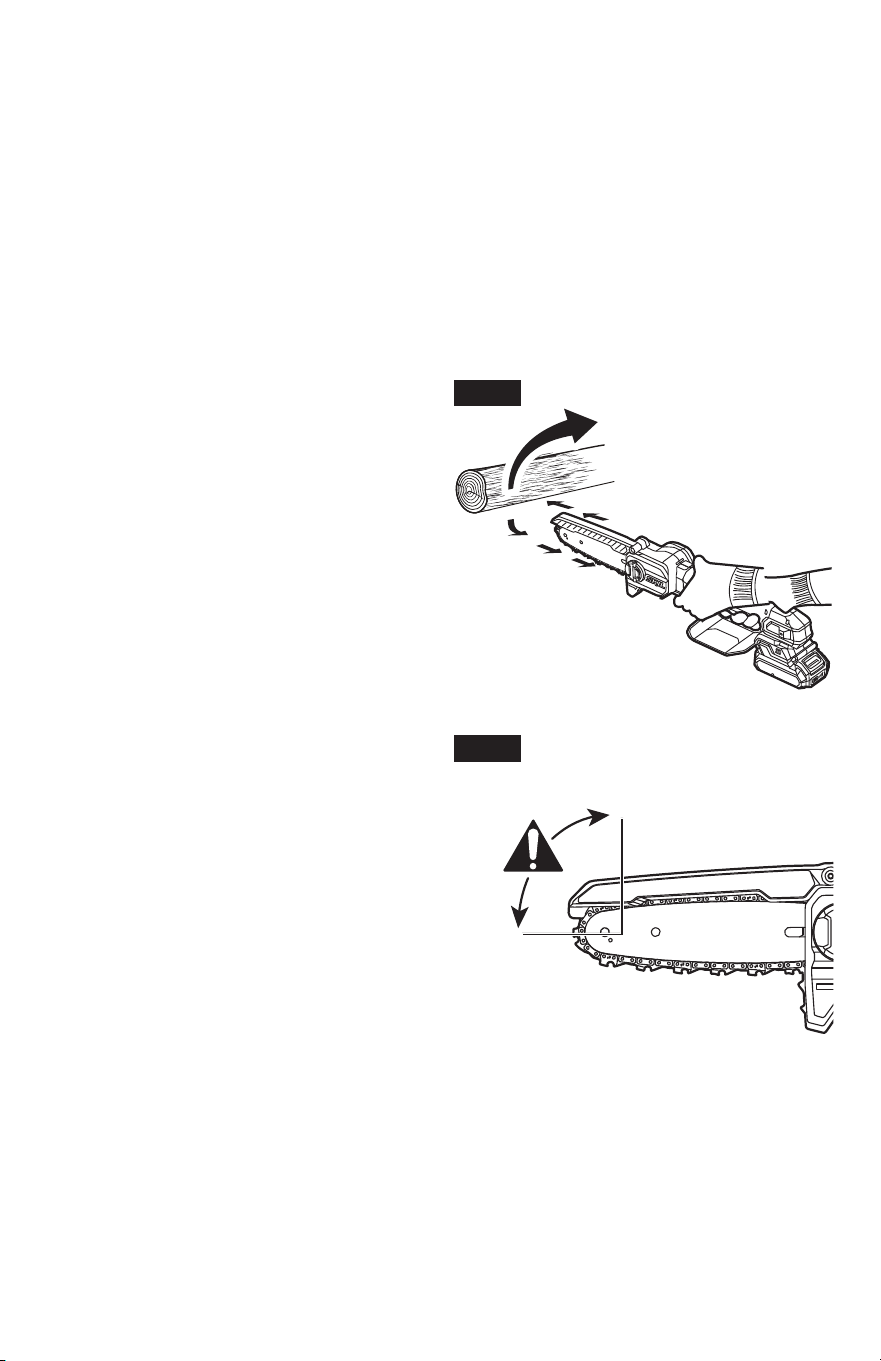
Causes and operator prevention
of kickback (Fig. 1, 2, 3):
Kickback may occur when the nose or tip of the
guide bar touches an object, or when the wood
closes in and pinches the saw chain in the cut.
Tip contact in some cases may cause a sud-
den reverse reaction, kicking the guide bar up
and back towards the operator.
Pinching the saw chain along the top of the
guide bar may push the guide bar rapidly back
towards the operator.
Either of these reactions may cause you to
lose control of the saw, which could result in
serious personal injury. Do not rely exclusively
upon the safety devices built into your saw. As
a pruning saw user, you should take several
steps to keep your cutting jobs free from acci-
dent or injury.
Kickback is the result of machine misuse and/
or incorrect operating procedures or conditions
and can be avoided by taking proper precau-
tions as given below:
Fig. 1
Rotational
kickback
Fig. 2
Kickback
danger zone
7
•
Hold the pruning saw with both hands,
thumbs and ngers around the handles
of the pruning saw. Bring your body
and arms in a position where you can
withstand the kickback. If appropriate
measures are taken, the operator can
control the kickback forces (Fig. 4).
Kickback forces can be controlled by the
operator, if proper precautions are taken. Do
not let go of the pruning saw.
•
Do not overreach and do not cut above
shoulder height.
This helps prevent
unintended tip contact and enables better
control of the pruning saw in unexpected
situations.
•
Only use replacement bars and chains specied by the manufacturer.
Incorrect
replacement bars and chains may cause chain breakage and/or kickback.
•
Follow the manufacturer’s sharpening and maintenance instructions for the saw
chain.
Decreasing the depth gauge height can lead to increased kickback.
TELESCOPIC
TELESCOPIC
BRUSHLESS
Fig. 4
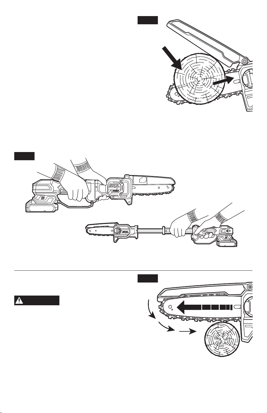
Causes and operator prevention
of pull-in (Fig. 5):
WARNING
•
Pull-in occurs when the chain on the bottom
of the bar is suddenly stopped or signicantly
slowed when it is pinched, caught or
encounters a foreign object in the wood. The
reaction of the chain pulls the saw forward
and may cause the operator to lose control,
which, in turn, may cause serious or fatal
injury.
•
Pull-in usually occurs when the bucking
spikes of the saw are not held securely
against the branch or limb and the chain is not rotating at full speed before it contacts the
wood.
Fig. 3
Pinch
Kickback
Fig. 5
8
•
To reduce the risk of pull-in:
–
Cut with a sharp, properly tensioned chain.
–
Always start a cut with the chain rotating at full speed and with the bucking spikes in contact
with the wood.
–
Use caution when cutting small-size brush, branches and saplings which may easily catch
the chain, spring towards you or pull you off balance.
–
Do not use the saw with a damaged or missing guard.
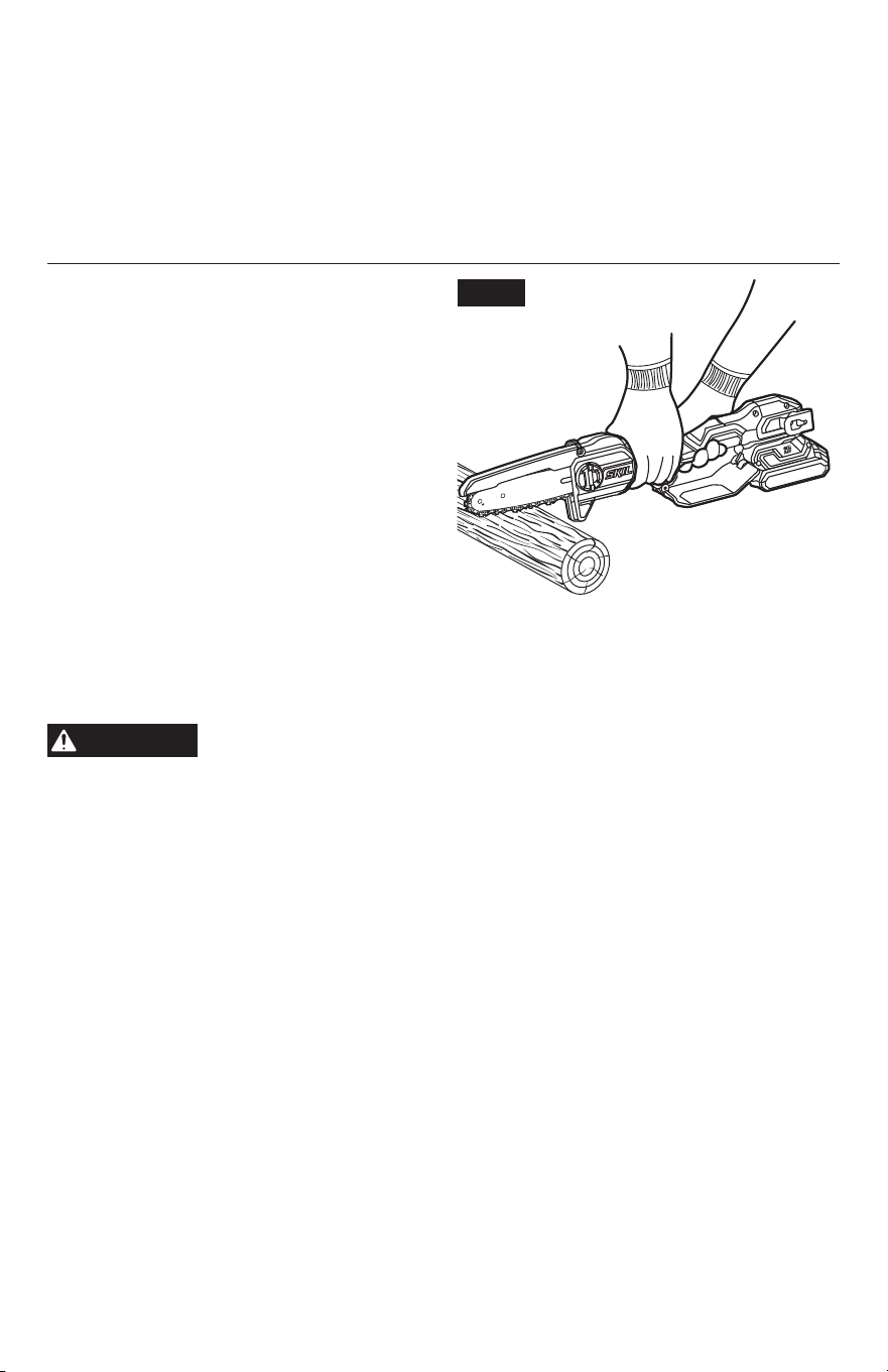
Additional Safety Warnings
Pull (Fig. 6)
– The reaction force is always
opposite to the direction the chain is moving
where wood contact is made. Thus, the oper-
ator must be ready to control the PULL when
cutting on the bottom edge of the bar.
Low Kickback Saw Chain
T
he rakers (depth gauges) ahead of each
cutter can minimize the force of a kickback
reaction by preventing the cutters from digging
in too deeply at the kickback zone. Only use
a replacement chain that is equivalent to the
original chain or has been certied as a low
kickback chain per ANSI B175.1. A low kickback tooth saw chain is a chain that has met the
kickback performance requirements of ANSI B175.1 (American National Standard for Power
Tools - Gasoline-Powered Chain saws - Safety Requirements) when tested on the representa-
tive sample of pruning saws below 3.8 c.i.d. specied in ANSI B175.1.
CAUTION
•
As saw chains are sharpened during their useful life, they lose some of the low kickback
qualities and extra caution should be used.
TELESCOPIC
BRUSHLESS
Fig. 6
9
SYMBOLS
Safety Symbols
The purpose of safety symbols is to attract your attention to possible dangers. The safety
symbols and the explanations with them deserve your careful attention and understanding. The
symbol warnings do not, by themselves, eliminate any danger. The instructions and warnings
they give are no substitutes for proper accident prevention measures.
WARNING
Be sure to read and understand all safety instructions in this Owner’s
Manual, including all safety alert symbols such as “
DANGER
”, “
WARNING
”,
and “
CAUTION
” before using this machine. Failure to following all instructions listed below may
result in electric shock, re, and/or serious personal injury.
The denitions below describe the level of severity for each signal word. Please read the
manual and pay attention to these symbols.
This is the safety alert symbol. It is used to alert you to potential
personal injury hazards. Obey all safety messages that follow this
symbol to avoid possible injury or death.
DANGER
DANGER indicates a hazardous situation which, if not avoided, will
result in death or serious injury.
WARNING
WARNING indicates a hazardous situation which, if not avoided,
could result in death or serious injury.
CAUTION
CAUTION, used with the safety alert symbol, indicates a hazardous
situation which, if not avoided, will result in minor or moderate
injury.
Damage Prevention and Information Messages
These inform the user of important information and/or instructions that could lead to equipment
or other property damage if they are not followed. Each message is preceded by the word
“NOTICE”, as in the example below:
NOTICE
Equipment and/or property damage may result if these instructions are not
followed.
WARNING
The operation of any power tools can result in foreign
objects being thrown into your eyes, which can result
in severe eye damage. Before beginning power tool operation, always
wear safety goggles or safety glasses with side shields and a full face
shield when needed. We recommend a Wide Vision Safety Mask for use
over eyeglasses or standard safety glasses with side shields. Always use
eye protection which is marked to comply with ANSI Z87.1.

10
SYMBOLS (CONTINUED)
IMPORTANT:
Some of the following symbols may be used on your tool. Please study them
and learn their meaning. Proper interpretation of these symbols will allow you to operate the
tool better and more safely.
Symbol Name Designation/Explanation
V Volts Voltage (potential)
A Amperes Current
Hz Hertz Frequency (cycles per second)
W Watt Power
kg Kilograms Weight
min Minutes Time
s Seconds Time
Wh Watt-hours Battery capacity
Ah Ampere-Hours Battery capacity
Ø Diameter Size of drill bits, grinding wheels, etc.
n
0
No load speed Rotational speed, at no load
n Rated speed Maximum attainable speed
…/min
Revolutions or reciprocations
per minute (rpm)
Revolutions, strokes, surface speed,
orbits, etc. per minute
O Off position Zero speed, zero torque...
1,2,3,… I,II,III, Selector settings
Speed, torque or position settings. Higher
number means greater speed
IP… Ingress Protection Degree
Classies the degree of protection
provided by an enclosure, for electrical
equipment.
Innitely variable selector
with off
Speed is increasing from 0 setting
Arrow Action in the direction of arrow
Alternating current (AC) Type or a characteristic of current
Direct current (DC) Type or a characteristic of current
Alternating or direct current
(AC / DC)
Type or a characteristic of current

11
Symbol Name Designation/Explanation
Class II machine
Designates Double Insulated Construction
machines.
Protective earth Grounding terminal
Li-ion RBRC seal
Designates Li-ion battery recycling
program
Read manual symbol Alerts user to read manual
Wear eye protection symbol
Always wear safety goggles or safety
glasses with side shields and a full face
shield when operating this product
Wear Ear Protection
Chain saw noise may damage your
hearing. Always wear sound barriers
(ear plugs or ear mufers) to protect your
hearing.
Wear Head Protection
Wear an approved safety hard hat to
protect your head.
Wear protective gloves Alerts user to wear protective gloves
Two handed hold
Always use two hands when operating the
chain saw.
Be aware of kickback
Contact of the guide bar tip with any
object should be avoided.
Guide bar tip kickback
Tip contact can cause the guide bar to
move suddenly upward and backward,
which can cause serious injury.

12
SYMBOLS (CERTIFICATION INFORMATION)
IMPORTANT:
Some of the following symbols for certication information may be used on your
tool. Please study them and learn their meaning. Proper interpretation of these symbols will
allow you to operate the tool better and more safely.
Symbol Designation/Explanation
This symbol designates that this machine is listed by Underwriters
Laboratories.
This symbol designates that this component is recognized by
Underwriters Laboratories.
This symbol designates that this machine is listed by Underwriters
Laboratories, to United States and Canadian Standards.
This symbol designates that this machine is listed by the Canadian
Standards Association.
This symbol designates that this machine is listed by the Canadian
Standards Association, to United States and Canadian Standards.
This symbol designates that this machine is listed by the Intertek
Testing Services, to United States and Canadian Standards.
801852
This symbol designates that this machine is listed by the SGS Testing
Services, to United States and Canadian Standards.
13
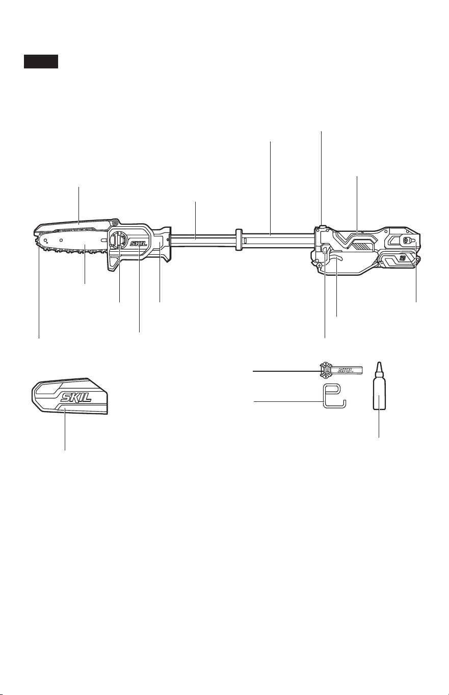
GET TO KNOW YOUR TELESCOPIC PRUNING SAW
TELESCOPIC
BRUSHLESS
Fig. 7
Chain Sheath
Rail Hook
Easy Storage Rail
Oil Dispensing Bottle
Lock-off Button
Trigger Switch
Storage clip
Main Handle
Auxiliary
Handle
Telescopic
Button
Telescopic
Pole
Kickback
Guard
Saw
Chain
Guide Bar
Side-cover
Knob
Auxiliary
Gripping Area
Side Cover
Main Handle
For grasping the saw.
Trigger Switch
Turns the pruning saw On and Off.
Lock-off Button
Helps to prevent accidental or unauthorized activation of the trigger switch. It must be
depressed before the trigger switch can be activated.

14
Telescopic Pole
Extends the reach of the pruning saw.
Telescopic Button
Unlocks the telescopic mechanism and allows the telescopic pole to be extended.
Auxiliary Handle
Part of the telescopic pole that, when extended, serves as an auxiliary.
Auxiliary Gripping Area
To hold the pruning saw with your other hand when the telescopic pole is collapsed.
Saw Chain
A loop of chain with cutting teeth, that when it is driven by the powerhead and supported by the
guide bar, cuts wood.
Kickback Guard
Protects the operator from being hurt by the saw kickback during operation.
Guide Bar
Supports and guides the saw chain.
Side-cover Knob
Locks/unlocks the side cover using foldable tab.
Side Cover
Covers the chain sprocket and secures the guide bar.
Chain Sheath
The chain sheath prevents the operator from coming in contact with the sharp chain teeth
when the machine is not in use. It also helps to protect the chain teeth from being nicked or
damaged during transportation and storage.
Easy Storage Rail
To hang the saw using the included rail hook.
Rail Hook
Used to conveniently hang the saw for storage.
Storage clip
To hang the saw on a nail, screw, or similar sturdy object.
Oil Dispensing Bottle
Used to apply chain oil.

15
SPECIFICATIONS
Model No. PR0601B-00
Rated Voltage 20 V d.c
Chain Speed 5 m/s
Cut Length 6 in. (150 mm)
Chain Pitch 1/4
ʺ
(6.35 mm)
Chain Gauge 0.043
ʺ
(1.1 mm)
Number of Chain Links 40
Recommended operating temperature 14 – 104 °F (-10 – 40 °C)
Recommended storage temperature 32 – 104 °F (0 – 40 °C)
Ingress Protection Rating IPX4* (Protection from splashing water)
* NOTE:
IPX4 rating is based on the machine and battery being used together as a system.
RECOMMENDED BAR AND CHAIN FOR THIS PRUNING SAW
PART NAME MODEL NUMBER
Guide Bar SBR0604Q
Saw Chain SCN0604Q
OPERATING INSTRUCTIONS
WARNING
To reduce the risk of re, personal injury, and product damage due to
a short circuit, never immerse your machine, battery pack, or charger
in uid or allow a uid to ow inside them.
Corrosive or conductive uids, such as seawater,
certain industrial chemicals, and bleach or bleach-containing products, etc., can cause a short
circuit.
WARNING
If any parts are damaged or missing, do not operate this product until
the parts are replaced.
Use of this product with damaged or missing parts
could result in serious personal injury.
WARNING
Do not attempt to modify this machine or create accessories not
recommended for use with this machine.
Any such alteration or
modication is misuse and could result in a hazardous condition leading to possible serious
injury.
WARNING
To prevent accidental starting that could cause serious personal
injury, always remove the battery pack from the machine when
assembling parts, making adjustments, cleaning, or performing maintenance.
16
This telescopic pruning saw must be used only with the SKIL battery packs and
chargers listed below:
Battery pack Charger
2Ah 2.5Ah 4Ah 5Ah SC535801
QC536001
SC5358B-02
QC5359B-02
SC0030B-00
BY519701
BY519702
BY5100B-00
BY519703 BY519601
BY5140B-00
BY519603
NOTICE
Please refer to the battery and charger manuals for detailed operating
information.
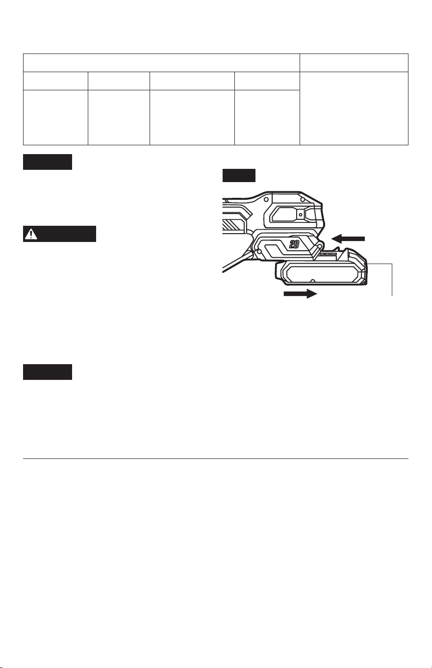
To Attach/Detach Battery Pack
(Fig. 8)
To attach battery pack
WARNING
Battery machines are
always in operating
condition. Therefore, always remove the
battery pack when the machine is not in use
or when carrying the saw at your side.
a. Align the raised portion on the battery
pack with the grooves on the bottom of the
machine, then slide the battery pack onto the
machine.
b. Make sure that the latches on the battery
pack snap into place and the battery pack is secured to the machine before beginning
operation.
NOTICE
When placing the battery pack on the machine, be sure that the raised rib on the
battery pack aligns with the groove on the machine and the latches snap into
place properly. Improper assembly of the battery pack can cause damage to internal
components.
To detach battery pack
a. Press the battery-release buttons to release the battery pack.
b. Pull backward on the battery pack to remove it from the machine.
TELESCOPIC
BRUSHLESS
Fig. 8
Battery-release
Button
Attach
Detach
17
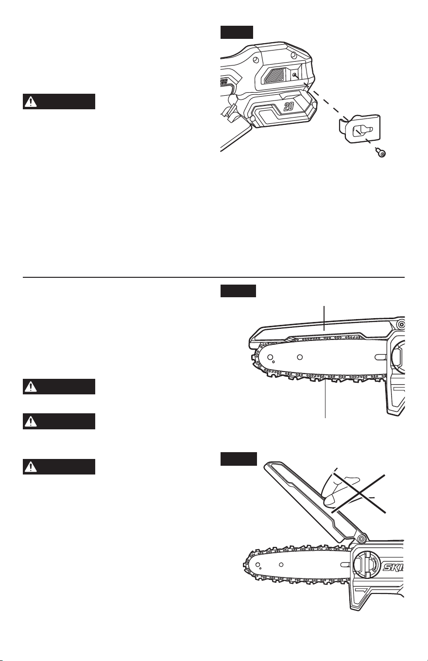
Installing and Removing Storage
Clip (Fig. 9)
Your machine includes a removable storage
clip that can be used to hang the saw on a nail,
screw, or similar sturdy object.
WARNING
To prevent the risk of injury,
always cover the saw chain
and bar with chain sheath before hanging the
saw.
To install:
a. Remove the battery pack from the machine.
b. Align the rib of the storage clip with the
threaded hole on the base of the machine.
c. Insert the screw provided and securely tighten the screw with a T20 Torx key (not included).
To remove:
a. Remove the battery pack from the machine.
b. Use a T20 Torx key (not included) to loosen the screw that attaches the storage clip to the
pruning saw.
c. Remove the screw and the storage clip. Store them in a safe place for future use.
Kickback and Pull-in Safety
Devices on This Telescopic
Pruning Saw
a. The pruning saw is equipped with a kickback
guard to lower risk of injury from kickback
(Fig. 10a) by preventing access to the saw
chain.
WARNING
To avoid injury, keep all
parts of your body away
from the guard during operation.
WARNING
For your safety, never
clamp or tie the kickback
guard in the open position. Do not attempt to
cut with the top edge of the bar (Fig. 10b).
WARNING
Always press the bucking
spikes against the material
being cut to maintain better control of the saw.
b. The saw is also equipped with an electric
brake, when the trigger switch is released,
the electric brake engages automatically to
quickly stop the chain rotation.
Fig. 9
Fig. 10a
Saw Chain
Kickback Guard
Fig. 10b
18
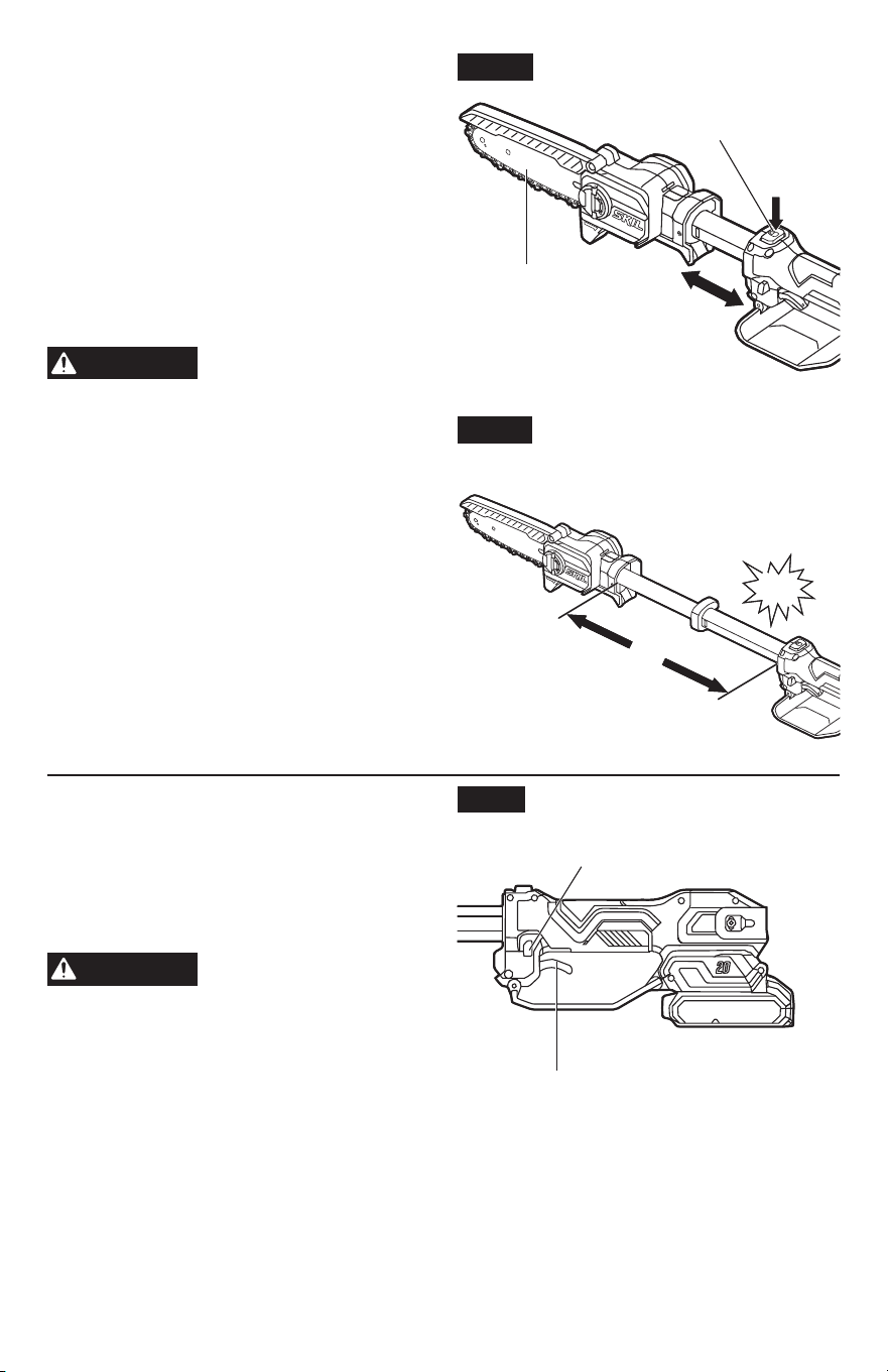
Adjusting the telescopic length
a. Press the telescopic button while pointing the
cutting head away from the you (1). Extend
the length of the telescopic pole by pulling it
forward from the main handle (2). It can also
be shortened by pulling it back towards the
main handle (Fig. 11a).
b. In the extended state, the telescopic pole can
be extended by 12-19/32” (320mm). Release
the telescopic button and make sure you
hear a “click”, indicating that the telescopic
pole is locked (Fig. 11b).
WARNING
To reduce the risk of injury,
the saw must be used with
the telescopic pole locked. Do not adjust the
telescopic length during use.
To Start/Stop the Telescopic
Pruning Saw (Fig. 12)
a. To turn the saw ON, grasp the main handle
rmly.
b. Press the lock-off button, and then squeeze
the trigger switch.
WARNING
Make sure no objects or
obstructions, which could
come in contact with the bar and chain, are in
the immediate vicinity.
c. To turn the saw OFF, release the trigger
switch and allow the chain to come to a
complete stop.
Fig. 11a
Telescopic
Button
Cutting
Head
Fig. 11b
12-19/32"
(320mm)
TELESCOPIC
BRUSHLESS
Fig. 12
Trigger Switch
Lock-off Button
Click
19
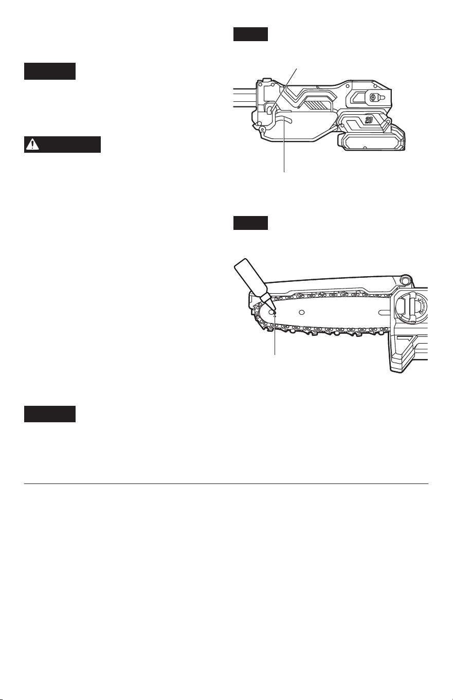
Lubricating the Saw Chain
(Fig. 13)
NOTICE
Chain life and cutting
performance depend on proper
lubrication. Therefore, the chain should be oiled
before operation.
NOTE:
Bar and chain oil is not included and
must be purchased separately.
WARNING
Do not smoke or bring any
re or ame near the oil or
the pruning saw. Oil may spill and cause a re.
a. Switch off the pruning saw and remove the
battery.
b. Place the pruning saw on a level surface with
the housing cover facing up.
c. Clean the guide bar and chain with a soft
brush or solvent if necessary.
d. Apply one drop of oil (not included) in the
area between guide bar and chain (Fig. 13).
Apply additional drop of oil after every 10
cuts.
e. Attach the battery pack and turn the pruning
saw on for a few seconds. This will evenly
distribute the oil.
f. In addition, the guide bar has a built-in
sprocket at its tip. The sprocket must be
lubricated weekly with an oil dispensing
bottle to extend the sprocket life. Use an
oil dispensing bottle to lubricate weekly by
means of the lubricating hole on each side of the bar.
NOTICE
•
Never use oil or other lubricants not specically designed for use on the bar and chain. This
can lead to a clogged oil system, which may cause premature wear of the bar and chain.
•
Do not use dirty, used, or otherwise contaminated oil. Damage may occur to the bar or chain.
TELESCOPIC
BRUSHLESS
Fig. 12
Trigger Switch
Lock-off Button
Fig. 13
Lubricating Hole

20
Before Using the Telescopic Pruning Saw:
a. Remove the battery pack.
b. Conrm that the kickback guard is undamaged and functioning properly.
c. Make sure that the chain is properly mounted and correctly tensioned: Lift the tip of the
guide bar up to check for any sagging in the saw chain. The saw chain is correctly tensioned
when there is no sag on the underside of the guide bar and the saw chain is snug, but it can
be turned by hand without binding. If the tension requires adjustment, refer to the chapter
“
Adjusting the Chain Tension
” in the “
Maintenance
” section of this manual for instructions.
d. Check the tightness of the side-cover knob before use. If it is loose, securely tighten the
side-cover knob by turning it clockwise.
e. Check the sharpness of the cutting teeth of the saw chain.
f. Make sure the saw chain is well lubricated.
g. Stand upright and hold the pruning saw in a relaxed position.
h. Make sure the saw chain is not touching the ground or any other objects.
i. Hold the saw rmly – refer to chapter “
Proper Grip on Handles
” below.
j. Make sure that you have a secure and balanced footing. Watch out for obstacles such as
tree stumps, roots, and ditches, which could cause you to trip or stumble.
k. Always make a trial cut in scrap material before making an accurate cut.
Preparation for Cutting
Refer to safety instructions earlier in this manual for appropriate safety equipment.
Work Area Precautions
•
Cut only wood or materials made from wood. Do not cut sheet metal, plastics, masonry, or
non-wood building materials.
•
Never allow children to operate the pruning saw.
•
Allow no person, who has not read this Owner’s Manual or received adequate instructions for
the safe and proper use of this saw, to use this saw.
•
During bucking operations, keep a minimum distance of 15 feet (4.5 m) between workers.
Tree branches should not be trimmed in a manner that would endanger any person, strike
any utility line, or cause any property damage. If a branch does make contact with any utility
line, stay clear of the tree and the line and notify the utility company immediately.
•
Always operate the saw with both feet on solid ground to prevent being pulled off balance.
•
Do not cut above chest height, as a saw held higher is difcult to control against kickback
forces.
•
Do not prune trees near electrical wires or buildings.
•
Cut only when visibility and light are adequate for you to see clearly.
21
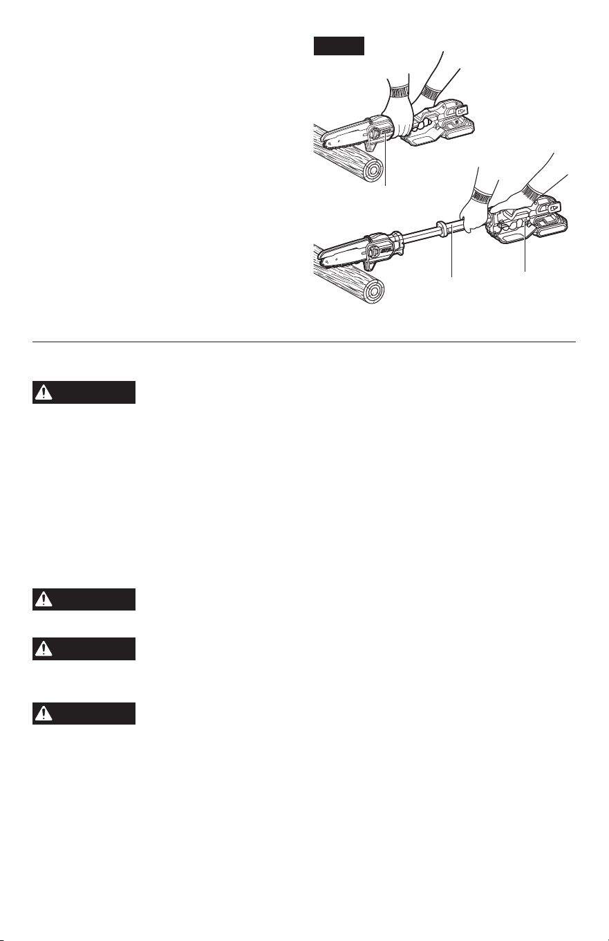
Proper Grip on Handles
•
Wear non-slip gloves for maximum grip and
protection.
•
With the saw on a rm, at surface, hold the
saw rmly by the main handle with one hand.
The ngers should encircle the handle. Use
your other hand to grab the auxiliary gripping
area from the side, as shown in Fig. 14.
•
In the extended position, hold the saw rmly
by the main handle with one hand and the
auxiliary handle with the other hand, as
shown in Figure 14.
Basic Cutting
WARNING
Always be sure of your footing and hold the pruning saw rmly with both
hands while the motor is running. Practice cutting a few small logs using
the following technique to get the “feel” of using your saw before you begin a major sawing
operation.
a. Take the proper stance in front of the wood with the saw off.
b. Press the lock-off button and squeeze the trigger to start the saw. Let the saw chain reach
the full speed before beginning the cut.
c. Begin cutting by lightly pressing the guide bar against the wood. Use only light pressure,
letting the saw do the work.
d. Maintain a steady speed throughout the cut, releasing pressure just before the end of the
cut.
e. Release the trigger as soon as the cut is completed, allowing the saw chain to stop.
WARNING
When the saw chain is stopped due to pinching during cutting, release the
trigger switch; remove the saw chain and guide bar from the wood, then
restart the pruning saw.
WARNING
Do not pull the saw chain with your hand when it is bound by the sawdust.
Serious injury could result if the saw starts accidentally. Press the saw
chain against the wood, move the saw back and forth to discharge the debris. Always remove
the battery pack before cleaning. Wear heavy protective gloves when handling the saw chain.
WARNING
Never start the pruning saw when it is in contact with the wood. Always
allow the saw to reach full speed before applying the saw to the wood.
NOTE:
For better performance, do not cut a branch with a diameter greater than 5-7/8 in.
(15 cm).
TELESCOPIC
BRUSHLESS
TELESCOPIC
BRUSHLESS
Fig. 14
Auxiliary
Gripping Area
Auxiliary
Handle
Main
Handle
22
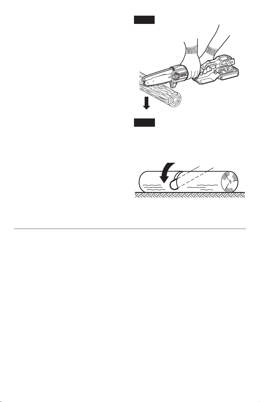
Limbing
Limbing is removing branches from a fallen
tree. When limbing, leave larger limbs to
support the log off the ground. Use the pruning
saw to remove the small limbs in one cut as
illustrated in Fig. 15.
WARNING
There is an extreme danger
of kickback during the
limbing operation. Be extremely cautious and
avoid contacting the log or other limbs with the
tip of the guide bar.
WARNING
The saw is not suitable for
bottom-up cutting as its
kickback guard must not be lifted during
operation. Never use it to cut the support
branches under tension.
NOTE:
For better performance, do not cut a branch with a diameter greater than 5-7/8 in.
(15 cm).
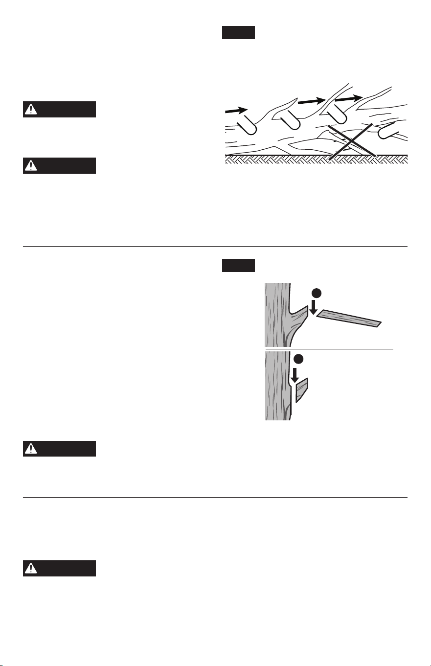
Pruning (Fig. 16)
Pruning is trimming limbs from a live tree.
•
Work slowly, keeping your hand on the
pruning saw with a rm grip. Always make
sure your footing is secure and your weight is
distributed evenly on both feet.
•
Do not cut from a ladder, this is extremely
dangerous. Leave this operation for
professionals.
•
Do not cut above shoulder height as a saw
held higher is difcult to control against
kickback.
•
When pruning trees, be aware of the risk of
stripping the bark from the main limb or trunk
when the cut is made next to the main limb or trunk.
WARNING
If the limbs to be pruned are above shoulder height, hire a professional to
perform pruning. Failure to do so could result in serious personal injury.
NOTE:
For better performance, do not cut a branch with a diameter greater than 5-7/8 in.
(15 cm).
Bucking a Log
Bucking is cutting a log into lengths. It is important to make sure your footing is rm and your
weight is evenly distributed on both feet. The log should be supported along its entire length.
Follow these simple directions for easy cutting.
WARNING
Keep the cutting area clear. Make sure that no objects can contact the
guide bar nose and chain during cutting. This can cause kickback.
Fig. 15
Limb out
Fig. 16
First cut to reduce load
Final Cut
1
2
23
Overbucking (Fig. 17a)
Begin on the top side of the log with the
bottom of the saw against the log, exert light
pressure downward. Note that the saw will tend
to pull away from you. Engage the pruning
saw bucking spikes against the log whenever
possible.
Make sure that the log is supported along its
entire length before you make a cut from the
top (overbucking) as shown in Fig. 17b.
NOTE:
For better performance, do not cut a log
with a diameter greater than 5-7/8 in. (15 cm).
•
When bucking on a slope, always stand on
the uphill side of the log.
•
To maintain complete control when cutting
through, release the cutting pressure near
the end of the cut without relaxing the grip on
the pruning saw handle. Don’t allow the chain
to contact the ground. After completing the
cut, wait for the saw chain to stop before you
move the saw. Always stop the motor before
moving from tree to tree.
TELESCOPIC
BRUSHLESS
Fig. 17a
Overbucking
Fig. 17b
Log supported along the entire length
Cut from top (overbuck).
Avoid cutting soil.

24
MAINTENANCE
WARNING
To avoid serious personal injury, always remove the battery pack from
the machine when cleaning or performing any maintenance.
A battery-
operated pruning saw with the battery pack inserted is always on and can start accidently.
WARNING
Always wear heavy gloves when handling the bar and chain. Be careful of
the saw chain and protect your hands from being injured by the saw chain.
WARNING
Always wear eye protection with side shields marked to comply with ANSI
Z87.1. Failure to do so could result in objects being thrown into your eyes
resulting in possible serious injury.
Service
WARNING
Preventive maintenance performed by unauthorized personnel may
result in misplacing of internal wires and components which could
cause a serious hazard.
We recommend that all service be performed by a SKIL Factory
Service Center or Authorized SKIL Service Station.
General Maintenance
WARNING
When servicing, use only identical replacement parts. Use of any
other parts could create a hazard or cause product damage.
Periodically inspect the entire product for damaged, missing, or loose parts such as screws,
nuts, bolts, caps, etc. Tighten securely all fasteners and caps and do not operate this product
until all missing or damaged parts are replaced. Please contact customer service an authorized
service center for assistance.
Cleaning
•
After each use, clean debris from the chain and guide bar with a soft brush. Wipe the pruning
saw surface with a clean cloth moistened with a mild soap solution.
•
Remove the side cover, and then use a soft brush to remove debris from the guide bar, saw
chain, sprocket, and side cover.
•
Always clean out wood chips, saw dust, and dirt from the guide bar groove when replacing
the saw chain.
All pruning saw service, other than the items listed in these maintenance instructions, should
be performed by competent service personnel.
Replacing the Bar and Chain
WARNING
Always wear protective gloves when handling the bar and chain. These
components are sharp and may contain burrs.
WARNING
Never touch or adjust the chain while the motor is running.
NOTICE
When replacing the guide bar and chain, always use the specied bar and chain
combination listed in this manual.
25
Disassembling the Worn Bar and
Chain
a. Remove the battery, allow the saw to cool.
b. Position the pruning saw on its side on a rm,
at surface, so that the side cover is facing
up.
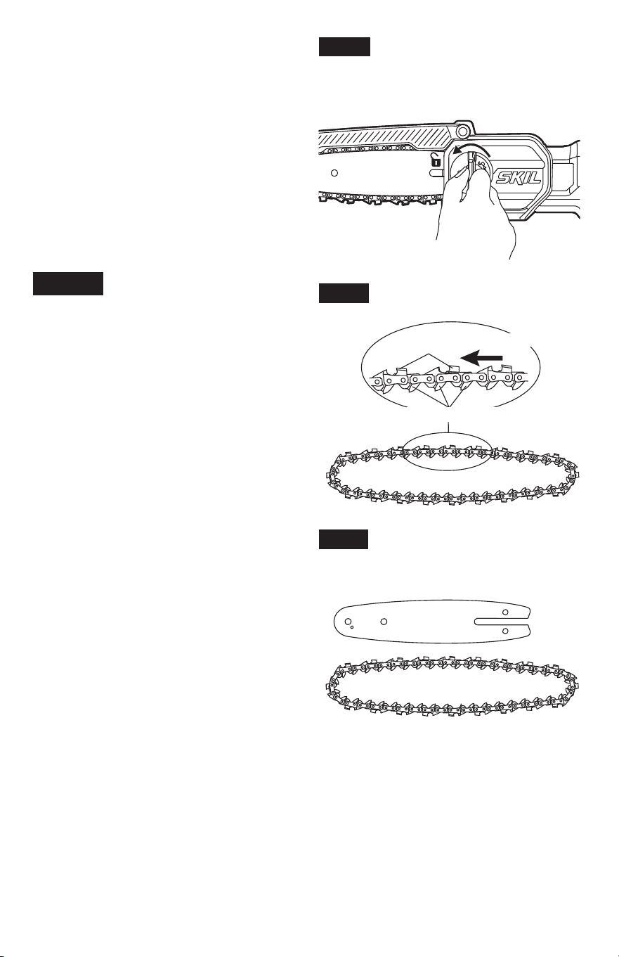
c. Lift the tab and rotate the side-cover knob
counterclockwise, then remove the side
cover. Clean the side cover with a dry cloth
(Fig. 18a).
d. Lift the kickback guard. Remove the bar
and saw chain from the mounting surface.
Remove the worn chain from the bar.
NOTICE
This is a good time to inspect the
drive sprocket for excessive wear
or damage.
Assembling the New Bar and
Chain
a. Remove the battery, allow the saw to cool.
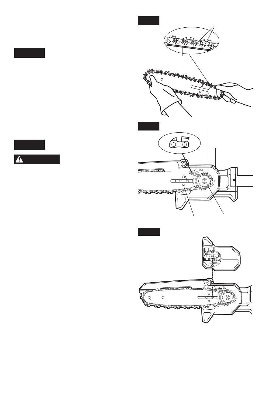
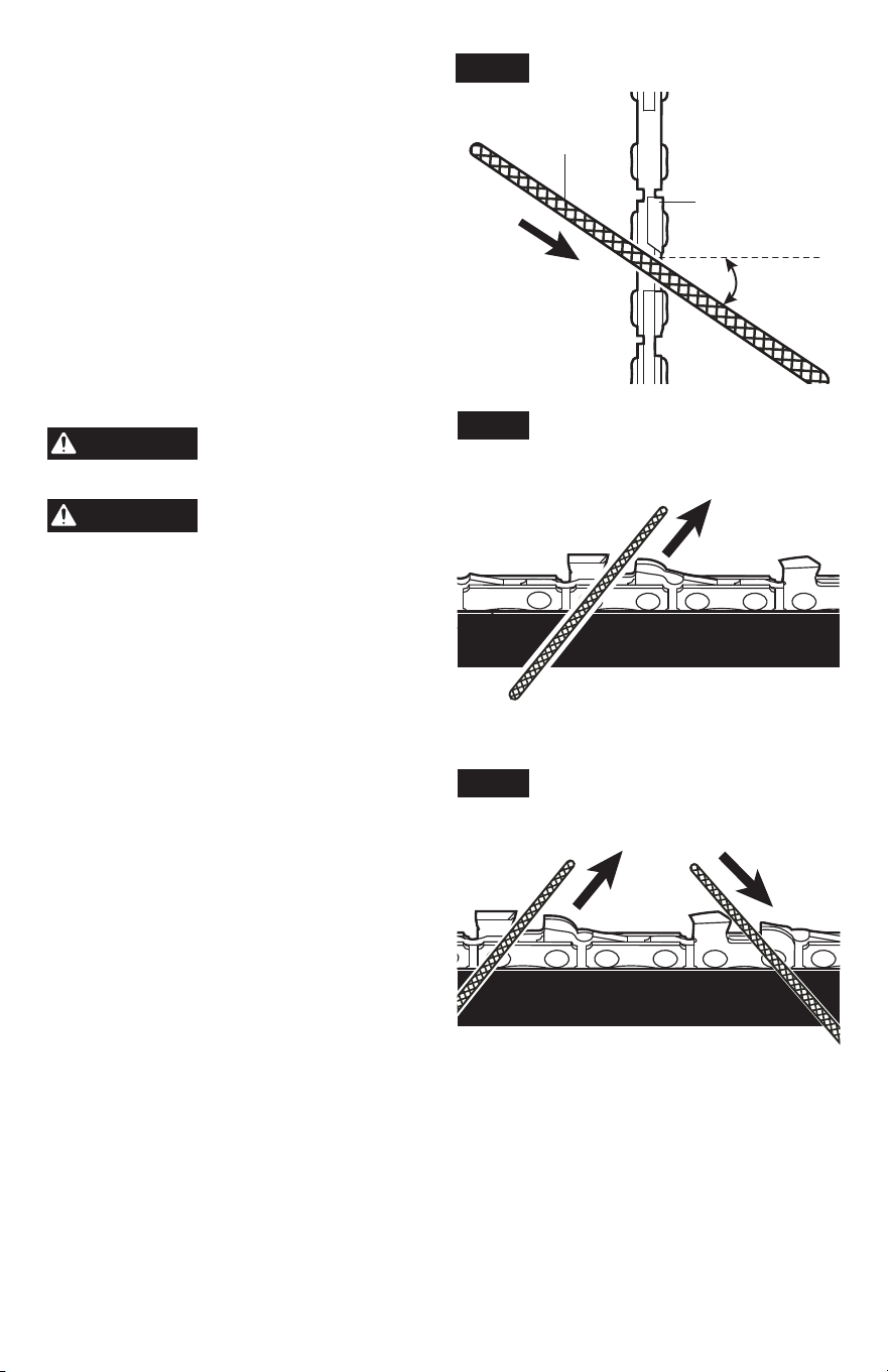
b. Lay the new saw chain in a loop on a at
surface and straighten any kinks. The cutters
should face in the direction of chain rotation,
if they face backwards, turn the loop over
(Fig. 18b & 18e).
Fig. 18a
Fig. 18b
Cutters
Chain rotation
Chain-drive Links
Fig. 18c
26
c. Place the chain-drive links into the guide-bar
groove. Position the chain so there is a loop
at the back of the guide bar (Fig. 18d).
d. Place the loop around the sprocket.
NOTICE
When looping the saw chain onto
the sprocket, make sure that the
direction of the saw chain cutters match the
cutter pattern and rotation direction arrow on
the housing. If they face in opposite directions,
turn over the saw chain and guide bar
assembly.
e. Lift the kickback guard. Place the guide bar
on the mounting surface by sliding the guide-
bar slot over the screw (Fig. 18e).
f. Replace the side cover and lightly tighten the
side-cover knob by turning it clockwise, but
do not fully tighten it (Fig. 18f).
NOTICE
To extend the guide bar life,
invert the bar occasionally.
CAUTION
The saw chain must be
properly tensioned before
using.
Fig. 18f
Fig. 18d
Chain-drive links
Bar groove
Fig. 18e
Rotation Direction Arrow
Cutter Pattern
Screw
Tension Pin
Sprocket
27
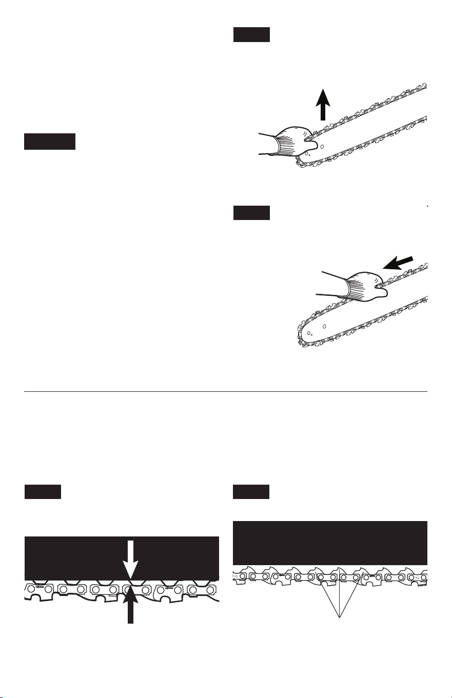
g. Lift the tip of the guide bar up to check for
sag (Fig. 18g). Hold the tip of the guide bar
up and tighten the side-cover knob securely
and fold the tab. The chain is automatically
tensioned now. The chain is correctly
tensioned when there is no sag on the
underside of the guide bar and the chain is
snug, but it can be turned by hand without
binding (Fig. 18h).
NOTICE
If chain is too tight, it will not
rotate. Loosen the side-cover
knob slightly. Lift the tip of the guide bar up and
retighten the side-cover knob securely. Assure
that the chain will rotate without binding.
Adjusting the Chain Tension
a. Stop the saw and remove the battery pack
before adjusting the chain tension.
b. Loosen the side-cover knob. This will release
the tension pin (shown in Fig. 18e) and
loosen the chain tension. Lift, pull and push
the guide bar to help adjust chain tension,
then retighten the side-cover knob securely.
Assure that the chain will rotate without
binding.
•
During normal saw operation, the temperature of the chain will increase. The drive links of
a correctly tensioned warm chain will hang approximately 0.050 in. (1.3 mm) out of the bar
groove (Fig. 19a).
•
A cold chain is correctly tensioned when there is no slack on the underside of the guide bar
and the chain is snug, but it can be turned by hand without binding. The chain must be re-
tensioned whenever the ats of the drive links do not sit in the bar groove (Fig. 19b).
Fig. 18g
Fig. 18h
Fig. 19a
Approximately 0.050" (1.3 mm)
Fig. 19b
Flats of drive links
28
NOTICE
New chains tend to stretch; check chain tension frequently and tension as
required.
NOTICE
A chain tensioned while it is warm may be too tight upon cooling. Check the cold
tension before next use.
Chain Maintenance
WARNING
Remove the battery pack before performing any maintenance. Failure to
heed this warning could result in serious personal injury.
WARNING
Always wear gloves when handling the saw chain. The chain is sharp and
may contain burrs.
Use only low-kickback chains on this saw. This fast-cutting chain will provide kickback
reduction when properly maintained.
A properly sharpened saw chain cuts through wood effortlessly, even with very little pressure.
Never use a dull or damaged saw chain. A dull saw chain cutter leads to increased physical
strain, increased vibration load, unsatisfactory cutting results and increased wear.
For smooth and fast cutting, the saw chain needs to be maintained properly. When the wood
chips are small and powdery, the chain must be forced through the wood during cutting,
or the chain cuts to one side are the indicators that the chain requires sharpening. During
maintenance of your saw chain, consider the following:
•
Improper ling angle of the side plate can increase the risk of a severe kickback.
•
Raker (depth gauge) clearance. Too low increases the potential for kickback. Not low enough
decreases cutting ability.
•
If cutter teeth have hit hard objects, such as nails and stones, or have been abraded by mud
or sand on the wood, have the chain sharpened by a qualied service technician.
NOTICE
Inspect the drive sprocket for wear or damage when replacing the chain. If signs
of wear or damage are present in the areas indicated, have the drive sprocket
replaced by qualied service technician.
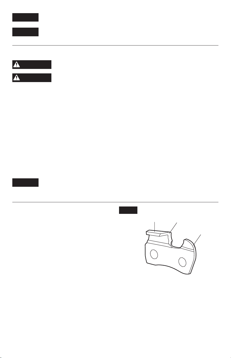
Sharpen the Cutters
Be sure to le all cutters (Fig. 20a) to the
specied angles and to the same length, as fast
cutting can be obtained only when all cutters
are uniform.
a. Remove the battery pack. Wear gloves for
protection.
b. Properly tension the chain prior to
sharpening. Refer to the section: “
Adjusting
the Chain Tension
” earlier in this manual.
c. Use a 1/8ʺ (3.2 mm) diameter round le and
holder (available separately). Do all of your
ling at the middle position of the guide bar.
d. Keep the le level with the top plate of the
tooth. Do not let the le dip or rock.
Fig. 20a
Top plate
Side plate
Depth
gauge
29
e. Keep a correct sharpening angle of 30°
between the le and the saw chain (see
Fig. 20b & 20c). Always use a le holder
(available separately) when sharpening saw
chains by hand. File holders have markings
for the sharpening angle.
f. Using light but rm pressure, perform a
stroke towards the front corner of the tooth.
Lift the le away from the steel on each
return stroke.
g. Make a few rm strokes on every tooth. File
all left hand cutters in one direction. Then
move to the other side and le the right-hand
cutters in the opposite direction. Occasionally
remove lings from the le with a wire brush
(Fig. 20d).
WARNING
Improper chain sharpening
increases the potential of
kickback.
WARNING
Failure to replace or repair
a damaged chain can cause
serious injury.
Fig. 20b
1/8" (3.2 mm)
Round le
Cutter tooth
Filing Direction
Sharpening
Angle: 30°
Fig. 20c
Fig. 20d
Left hand
cutters
Right hand
cutters
30
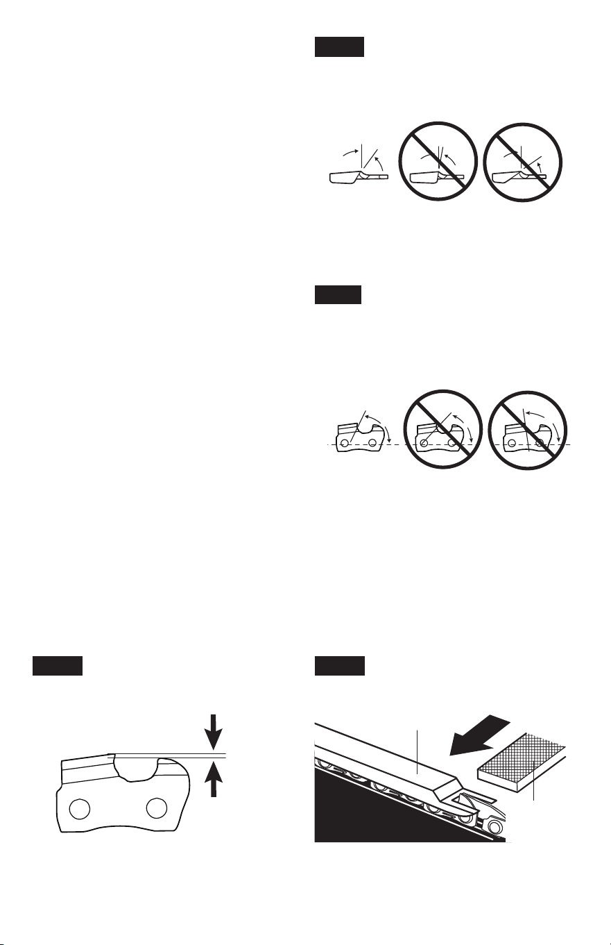
Top Plate Sharpening Angles
(Fig. 20e)
CORRECT 30°- This optimal angle can be
obtained only when the specied les and
proper setting are used. File holders are
marked with guide marks to align the le
properly to produce the correct top plate angle.
LESS THAN 30°- The tooth is too dull for
cutting.
MORE THAN 30°- The edge of the cutting tooth
is feathered and dulls quickly.
Side Plate Angle (Fig. 20f)
CORRECT 40° - The optimal angle can be
produced automatically if the correct diameter
le is used in the le holder.
HOOK - “Grabs” and dulls quickly. Increases
potential of KICKBACK. Results from using a
le with a diameter that is too small, or a le
held too low.
BACKWARD SLOPE - Needs too much feed
pressure, causes excessive wear to bar and
chain. Results from using a le with a diameter
too large, or a le held too high.
Depth-Gauge Clearance
a. The depth gauge should be maintained at a
clearance of 0.025 in. (0.6 mm), as shown in
Fig. 20g. Use a depth gauge tool (available
separately) to check the depth gauge
clearances.
b. Check the depth-gauge clearance every time the chain is led.
Use a at le and a depth-gauge jointer (both available separately) to lower all gauges
uniformly (Fig. 20h). Use a 0.025 in. (0.6 mm) depth-gauge jointer.
Depth-gauges must be adjusted with the at le in the same direction the adjoining cutter was
led with the round le. Use care not to contact the cutter face with the at le when adjusting
depth gauges.
30°
Fig. 20e
CORRECT INCORRECT INCORRECT
Top plate sharpening angles
Less than 30° More than 30°
40°
Fig. 20f
Side plate angle
Hook
Backward
Slope
CORRECT INCORRECT INCORRECT
Fig. 20g
Depth gauge clearance
0.025" (0.6 mm)
Fig. 20h
Flat le
Depth gauge jointer
31
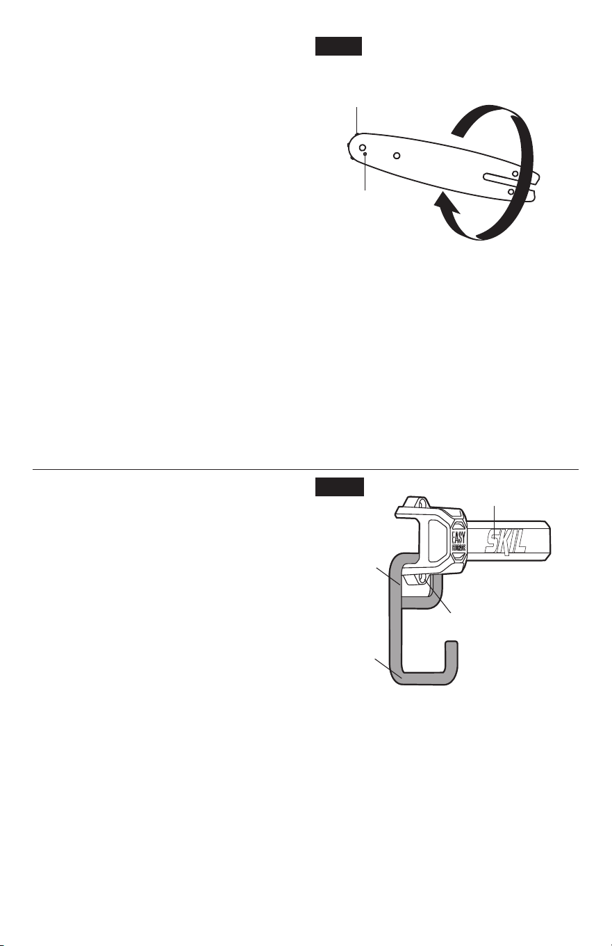
Guide Bar Maintenance
The bar should be cleaned every day of use
and checked for wear and damage. Feathering
or burring of the bar rails is a normal process of
bar wear. Such faults should be smoothed with
a le as soon as they occur. A bar with any of
the following faults should be replaced:
•
Wear inside the bar rails that permits the saw
chain to lay over sideways.
•
Bent guide bar.
•
Cracked or broken rails.
•
Spread rails.
In addition, the guide bar has a sprocket at its
tip. The sprocket must be lubricated weekly with a grease syringe to extend the guide bar life.
Use a grease syringe to lubricate weekly with chain oil by means of the lubricating hole (Fig.
21) on each side of the bar. Turn the guide bar and check that the lubrication holes and chain
groove are free from impurities.
When the guide bar shows signs of wear, reverse it on the saw to distribute the wear for
maximum bar life.
a. Remove the guide bar and chain from the pruning saw, following the section “
Replacing the
Bar and Chain
”.
b. Turn the guide bar over. The bottom of the bar will be on the top (Fig. 21).
c. Adjust the chain tension, following the section “
Adjusting the Chain Tension
”.
Transporting and Storing
•
Switch the product off and remove the battery
pack.
•
Clean the product and place the chain sheath
onto the guide bar and chain.
•
Clean the product and empty the oil tank.
•
Store the product and its accessories in a
dark, dry, frost-free, well-ventilated place.
•
Always store the product in a place that is
inaccessible to children. The ideal storage
is under room temperature. Use caution to
avoid the sharp teeth of the chain.
•
Keep away from corrosive agents such as
garden chemicals and de-icing salts.
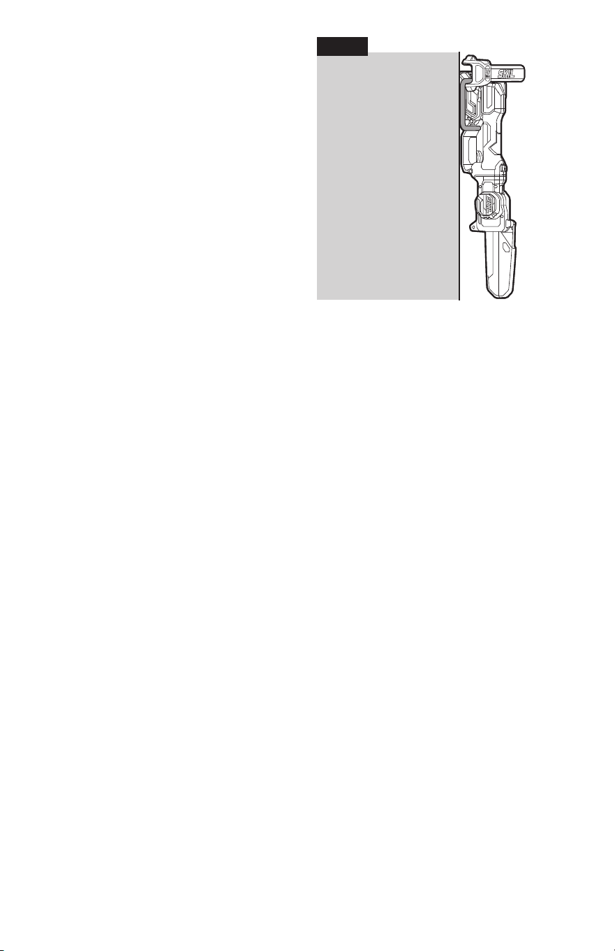
The saw can be hung on a nail, screw, or similar sturdy object using the storage clip. You can
also hang the machine on the included hanging set for convenient storage:
a. Hang the loop of the rail hook on the base of the easy storage rail (Fig. 22a).
Fig. 21
Lubricating hole
Sprocket in
guide bar tip
Fig. 22a
Easy Storage Rail
Loop
Rail Hook
Base
32
b. Horizontally level and securely mount the
easy storage rail on the wall with 2 #6×1”
screws (not supplied) to secure the rail hook
between the base and the wall.
c. Remove the battery pack – the saw cannot
be hung with the battery pack attached.
d. Hang the machine onto the rail hook as
shown (Fig. 22b).
Fig. 22b

33
TROUBLESHOOTING
Problem Cause Remedy
Machine fails
to start or stops
unexpectedly.
1. Battery pack charge is
depleted.
1. Charge the battery pack.
2. Battery pack is not installed
properly.
2. Conrm that the battery pack is locked
and secured to the machine.
Motor runs but
chain does not
rotate.
1. Chain does not engage
drive sprocket.
1. Reinstall the chain, making sure that
the drive links on the chain are fully
seated on the sprocket.
2. Chain tension is too tight. 2. Re-tension the chain. Refer to the
“
Adjusting the Chain Tension
”
chapter in this manual.
Motor runs, chain
rotates but does
not cut.
1. Dull chain. 1. Replace or sharpen the chain.
2. Chain is installed
backwards.
2. Reinstall the chain to reverse the
direction of the chain.

34
LIMITED WARRANTY OF SKIL CONSUMER MACHINES
5 YEAR LIMITED WARRANTY
Chervon North America, Inc. (“Seller”) warrants to the original purchaser only, that all SKIL
consumer MACHINES will be free from defects in material or workmanship for a period of ve
years from date of purchase, if original purchaser registers the product within 30 days from
purchase. BATTERIES AND CHARGERS are warranted for 2 years. Product registration can
be completed online at www.Registermyskil.com. Original purchasers should also retain their
receipt as proof of purchase. THE FIVE-YEAR WARRANTY PERIOD FOR MACHINES IS
CONDITIONED ON REGISTRATION OF THE PRODUCT WITHIN 30 DAYS OF PURCHASE.
If original purchasers do not register their product within 30 days of purchase, the foregoing
limited warranty will apply for a duration of three years for machines. All batteries and chargers
will remain under the two-year limited warranty.
Notwithstanding the foregoing, if a SKIL consumer machine is used for industrial, professional,
or commercial purposes, the foregoing warranty will apply for a duration of ninety days,
regardless of registration.
SELLER’S SOLE OBLIGATION AND YOUR EXCLUSIVE REMEDY under this Limited
Warranty and, to the extent permitted by law, any warranty or condition implied by law, shall
be the repair or replacement of parts, without charge, which are defective in material or
workmanship and which have not been misused, carelessly handled, or repaired by persons
other than Seller or Authorized Service Station. To make a claim under this Limited Warranty,
you must return the complete product, transportation prepaid, to any SKIL Factory Service
Center or Authorized Service Station. For Authorized SKIL Machine Service Stations, please
visit www.Registermyskil.com or call 1-877-SKIL-999 (1-877-754-5999).
THIS WARRANTY DOES NOT COVER ROUTINE MAINTENANCE PARTS AND
CONSUMABLES THAT CAN WEAR OUT FROM NORMAL USE WITHIN THE WARRANTY
PERIOD, INCLUDING BLADES, TRIMMER HEADS, CHAIN BARS, SAW CHAINS, BELTS,
SCRAPER BARS, AND BLOWER NOZZLES.
ANY IMPLIED WARRANTIES APPLICABLE TO A PRODUCT SHALL BE LIMITED IN
DURATION EQUAL TO THE DURATION OF THE EXPRESS WARRANTIES APPLICABLE TO
SUCH PRODUCT, AS SET FORTH IN THE FIRST PARAGRAPH ABOVE. SOME STATES IN
THE U.S., SOME CANADIAN PROVINCES DO NOT ALLOW LIMITATIONS ON HOW LONG
AN IMPLIED WARRANTY LASTS, SO THE ABOVE LIMITATION MAY NOT APPLY TO YOU.
THIS WARRANTY DOES NOT COVER THE DAMAGE RESULTING FROM MODIFICATION,
ALTERATION, OR UNAUTHORIZED REPAIR.
IN NO EVENT SHALL SELLER BE LIABLE FOR ANY INCIDENTAL OR CONSEQUENTIAL
DAMAGES (INCLUDING BUT NOT LIMITED TO LIABILITY FOR LOSS OF PROFITS)
ARISING FROM THE SALE OR USE OF THIS PRODUCT. SOME STATES IN THE U.S.
AND SOME CANADIAN PROVINCES DO NOT ALLOW THE EXCLUSION OR LIMITATION
OF INCIDENTAL OR CONSEQUENTIAL DAMAGES, SO THE ABOVE LIMITATION OR
EXCLUSION MAY NOT APPLY TO YOU.
THIS LIMITED WARRANTY GIVES YOU SPECIFIC LEGAL RIGHTS, AND YOU MAY ALSO
HAVE OTHER RIGHTS WHICH VARY FROM STATE TO STATE IN THE U.S., PROVINCE TO
PROVINCE IN CANADA AND FROM COUNTRY TO COUNTRY. THIS LIMITED WARRANTY
APPLIES ONLY TO PRODUCTS SOLD WITHIN THE UNITED STATES OF AMERICA,
CANADA AND THE COMMONWEALTH OF PUERTO RICO. FOR WARRANTY COVERAGE
WITHIN OTHER COUNTRIES, CONTACT YOUR LOCAL SKIL DEALER OR IMPORTER.
© Chervon North America, 1203 E. Warrenville Rd, Naperville, IL 60563.

11/23
