
Technical Support and E-Warranty Certificate
www.vevor.com/support
MICRO INVERTER
MODEL:GT-600/GT-800/GT-1200
We continue to be committed to provide you tools with competitive price.
"Save Half", "Half Price" or any other similar expressions used by us only represents an
estimate of savings you might benefit from buying certain tools with us compared to the major
top brands and does not necessarily mean to cover all categories of tools offered by us. You
are kindly reminded to verify carefully when you are placing an order with us if you are
actually saving half in comparison with the top major brands.

- 1 -
MODEL:GT-600/GT-800/GT-1200
GT-600/GT-800 GT-1200
Have product questions? Need technical support? Please feel free to
contact us:
Technical Support and E-Warranty Certificate
www.vevor.com/support
NEED HELP? CONTACT US!
This is the original instruction, please read all manual instructions
carefully before operating. VEVOR reserves a clear interpretation of our
user manual. The appearance of the product shall be subject to the
product you received. Please forgive us that we won't inform you again if
there are any technology or software updates on our product.
MICRO INVERTER

- 2 -
Warning-To reduce the risk of injury, user must read instructions
manual carefully.
This product is subject to the provision of European Directive
2012/19/EC. The symbol showing a wheelie bin crossed
through indicates that the product requires separate refuse
collection in the European Union. This applies to the product
and all accessories marked with this symbol. Products marked
as such may not be discarded with normal domestic waste, but
must be taken to a collection point for recycling electrical and
electronic devices
WARNING: DANGER OF ELECTRICAL SHOCK
The product is used in combination with a permanent energy source
(battery). Even if the equipment is switched off, a dangerous
electrical voltage can occur at the input and/or output terminals. Always
switch the AC power off and disconnect the battery before
performing maintenance.
The product contains no internal user-serviceable parts. Do not remove the
front panel and do not put the product into operation unless all panels are
fitted. All maintenance should be performed by qualified personnel.
Never use the product at sites where gas or dust explosions could occur.
Refer to the specifications provided by the manufacturer of the battery to
ensure that the battery is suitable for use with this product. The battery
manufacturer's safety instructions should always be observed.
WARNING: do not lift heavy objects unassisted.
Installation
Read the installation instructions before commencing installation activities.
This product is a safety class I device (supplied with a ground terminal for
safety purposes). Its AC input and/or output terminals must be provided
with uninterruptible grounding for safety purposes. An additional grounding
point is located on the outside of the product. If it can be assumed that the
grounding protection is damaged, the product should be taken out of

- 3 -
operation and prevented from accidentally being put into operation again;
contact qualified maintenance personnel.
Ensure that the connection cables are provided with fuses and circuit
breakers. Never replace a protective device by a component of a
different type. Refer to the manual for the correct part.
Check before switching the device on whether the available voltage source
conforms to the configuration settings of the product as described in the
manual.
Ensure that the equipment is used under the correct operating conditions.
Never operate it in a wet or dusty environment.
Ensure that there is always sufficient free space around the product for
ventilation, and that ventilation openings are not blocked.
Install the product in a heatproof environment. Ensure therefore that there
are no chemicals, plastic parts, curtains or other textiles, etc.
in the immediate vicinity of the equipment.
Transport and storage
On storage or transport of the product, ensure that the mains supply and
battery leads are disconnected.
No liability can be accepted for damage in transit if the equipment is not
transported in its original packaging.
Store the product in a dry environment; the storage temperature should
range from –40°C to 65°C.
Refer to the battery manufacturer's manual for information on transport,
storage, charging, recharging and disposal of the battery.
- 4 -
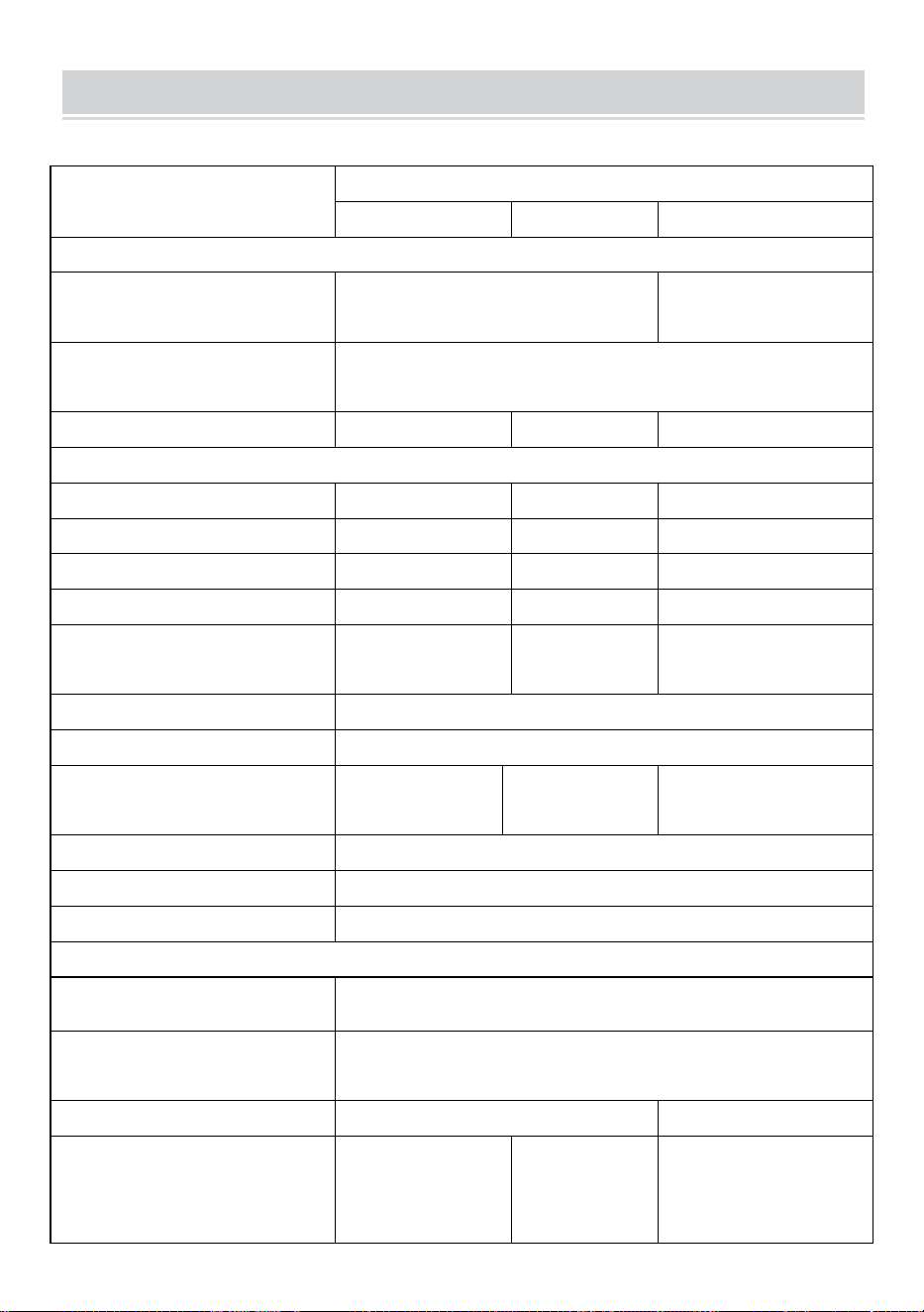
SPECIFICATIONS
You are welcome to choose our micro grid-connected solar inverter products.
Specification data
Model
GT-600
GT-800
GT-1200
Input Data (DC, PV)
Number of Input MC4 Connector
2 sets
4 sets
Operation Voltage Range
DC18V-50V
Maximum input Current
12A*2
14A*2
16A*2
Output Data(AC)
Single-Phase Grid Type
AC230V
AC230V
AC110V or AC230V
Maximum Output Power
600W
800W
1200W
Nominal Output Current
2.6A
3.5A
10.9A or 5.2A
Nominal Output Voltage
AC230V
AC230V
AC110V or AC230V
Output Frequency Range
50Hz
50Hz
60Hz or 50Hz
Power Factor
≥0.99%
Total Harmonic Distortion
THD <5%
Maximum Units per Branch
@230VAC:4units
@230VAC:3units
@110VAC:2units Or @230VAC:3units
Peak Efficiency
95%
Nominal MPPT Efficiency
99.5%
Night Power Consumption
≤1W
Mechanical Data
Operating Ambient Temperature
Range
-40℃ to +65℃
Storage Temperature Range
-40°C to +85C
Dimensions(W*H *D)
305 * 186 * 44mm
490 * 254 * 50mm
Waterproof Grade
IP67
IP65/IP67
(Please refer
to the product
nameplate
information)
IP67
Communication
WIFI(Cloud monitoring)
Protection Functions
Isolated Island Protection,Voltage Protection
Frequency Protection
Temperature Protection,Current Protection, etc.
- 5 -
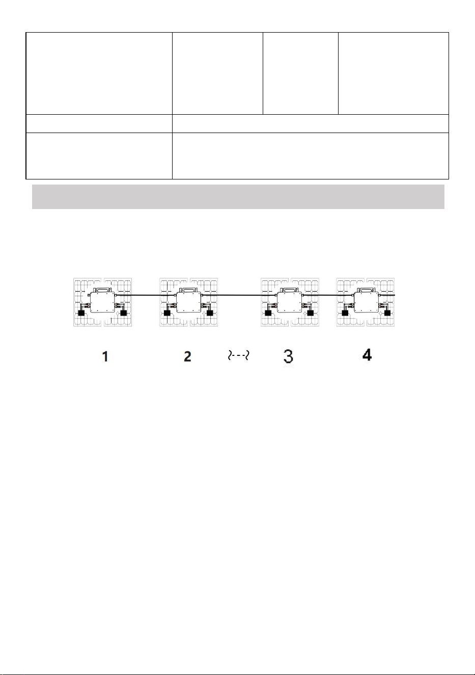
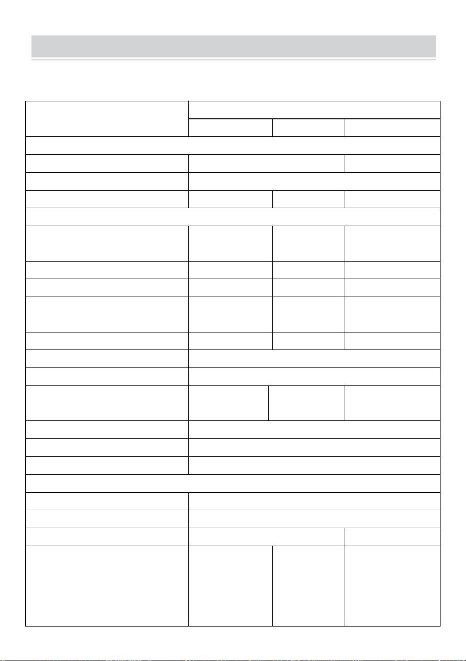
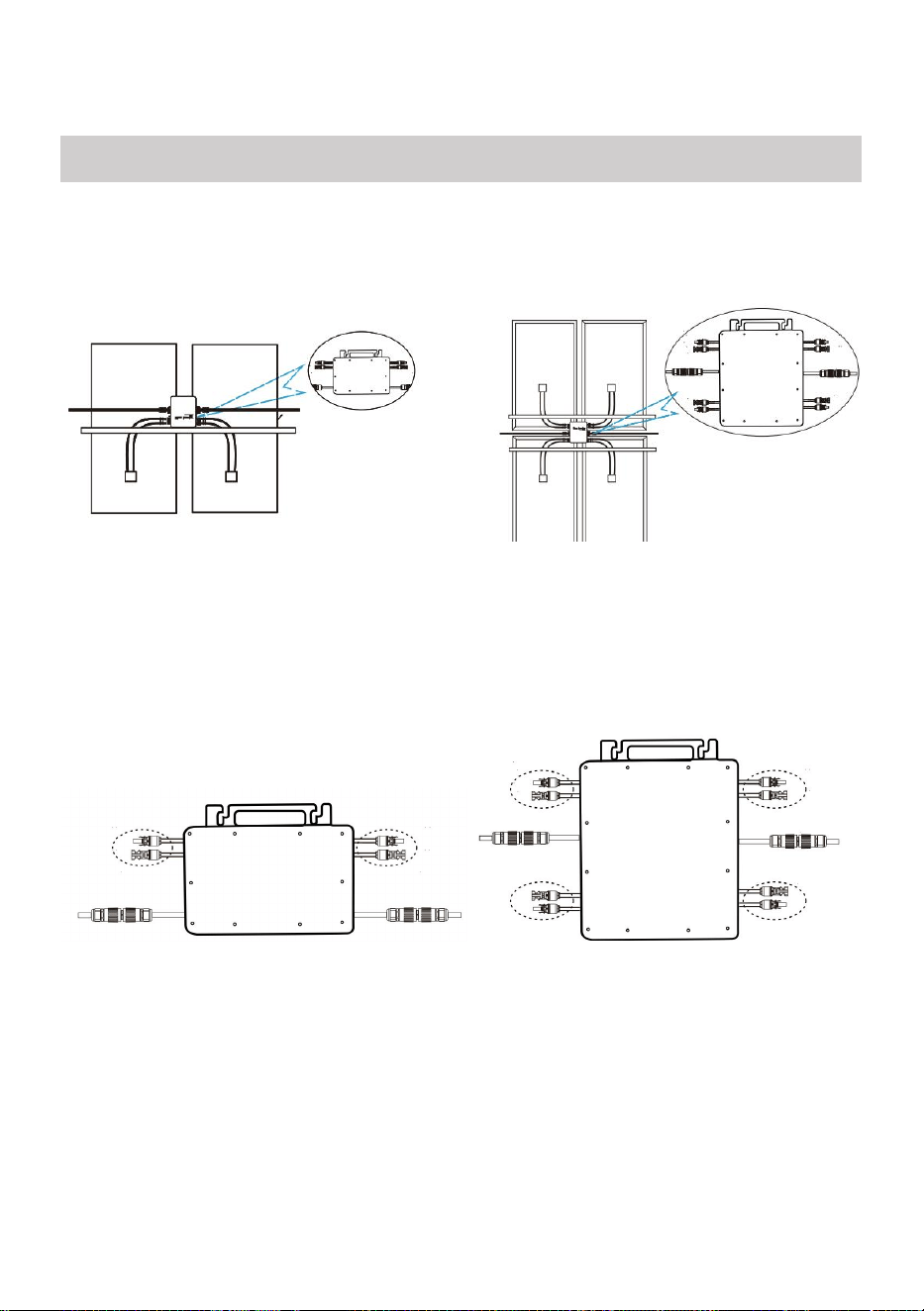
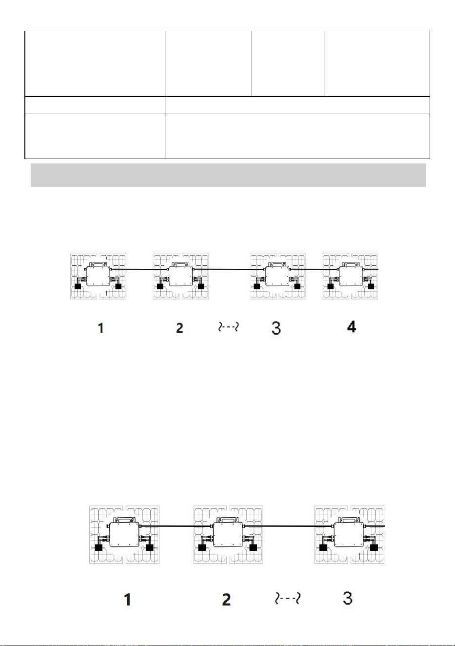
INSTALLATION SCHEMATIC
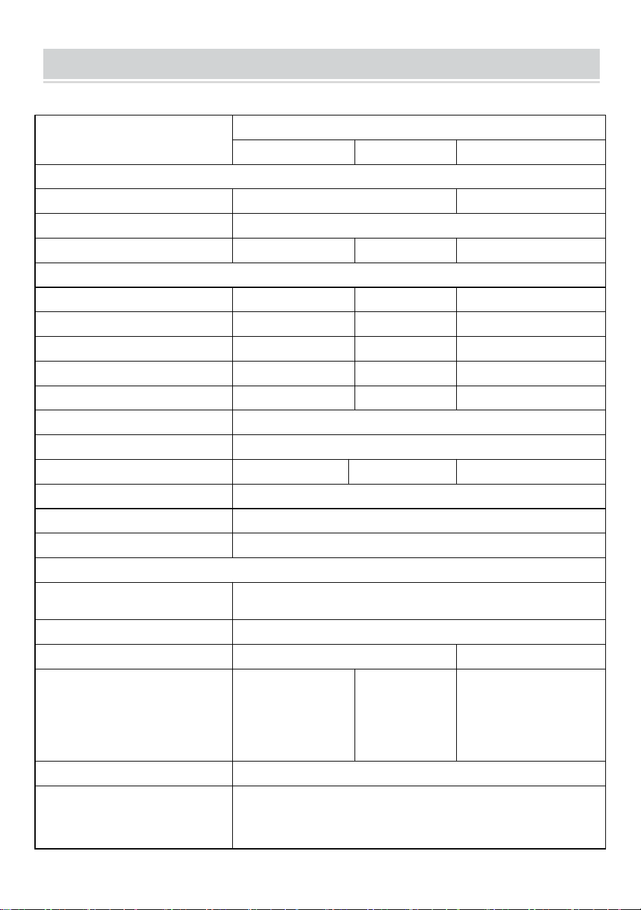
Single-phase parallel assembly method of micro inverter
GT-600
1. @Single-Phase 230V grid Maximum 4 units 600W Micro inverters per branch.
2. The max DC input power of each inverter is 600W(the PV module max output
power is 2x300W).
3. The VOC of PV modules should not be greater than the max DC input voltage
of Micro inverters.
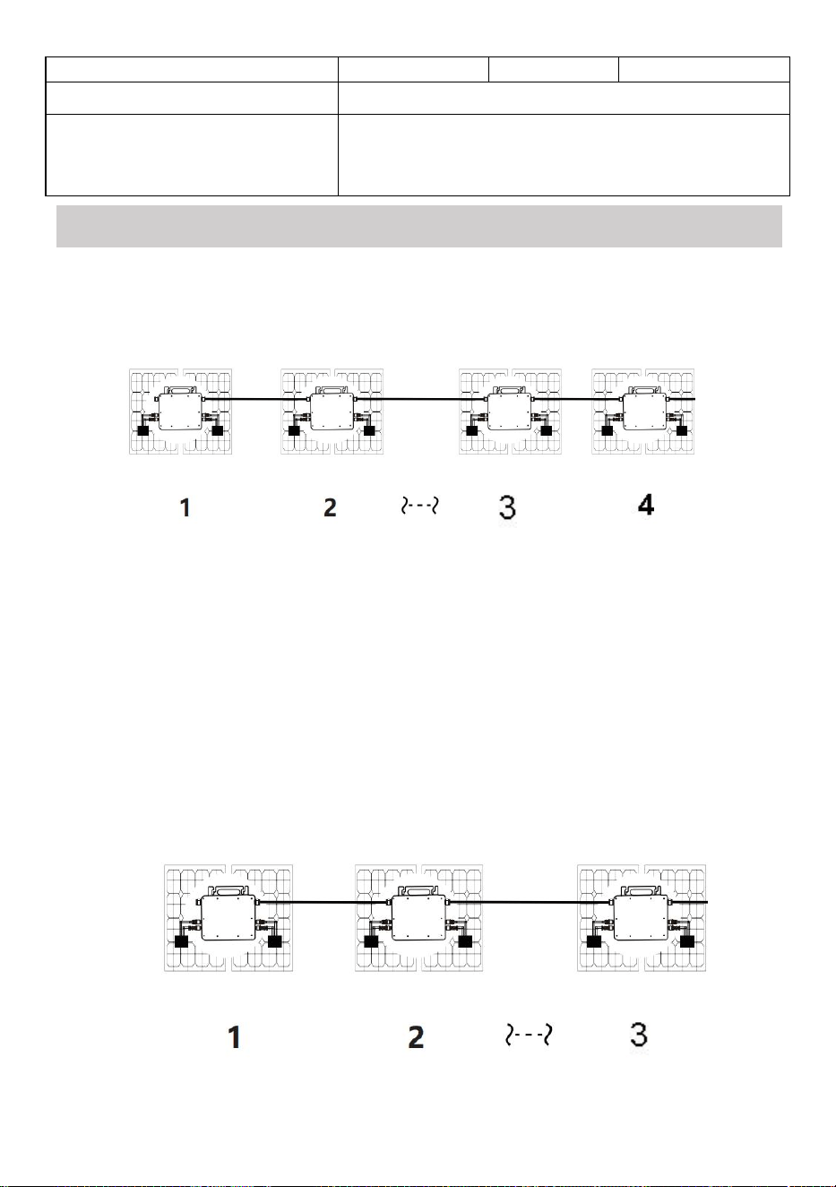
GT-800
1. @Single-Phase 230V grid Maximum 3 units 800W Micro inverters per branch.
2. The max DC input power of each inverter is 800W(the PV module max output
power is 2x400W).
3. The VOC of PV modules should not be greater than the max DC input voltage
of Micro inverters.
- 6 -
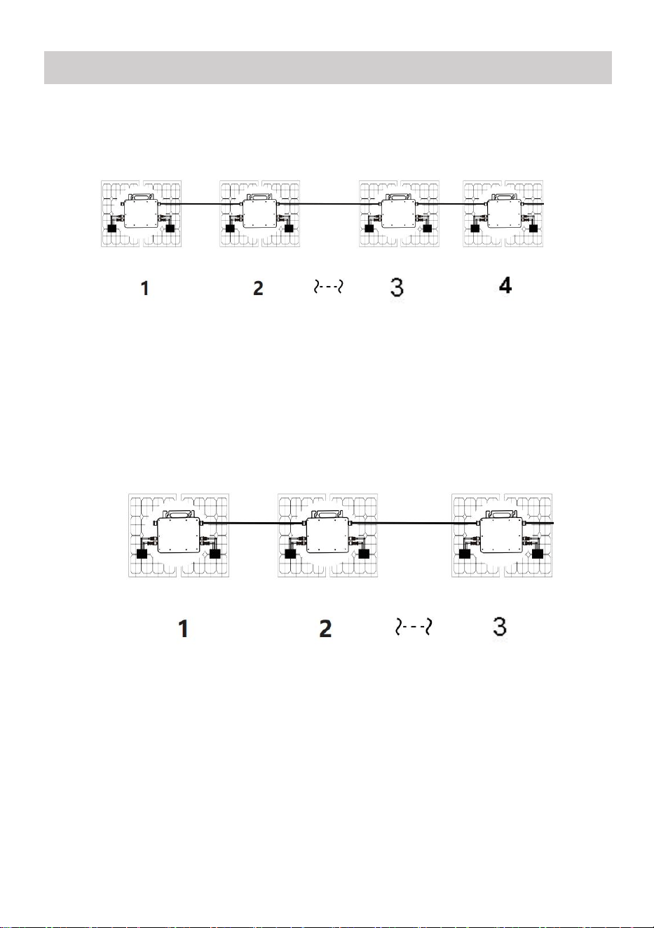
GT-1200
1. @Single-Phase 110V grid Maximum 2 units or @Single-Phase 230V grid
Maximum 3 units 1200W Micro inverters per branch.
2. The max DC input power of each inverter is 1200W(the PV module max output
power is 2x600W).
3. The VOC of PV modules should not be greater than the max DC input voltage
of Micro inverters.
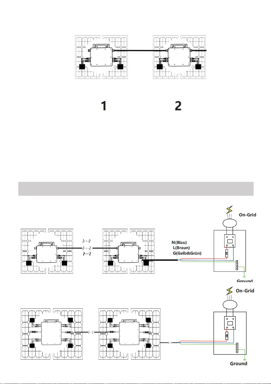
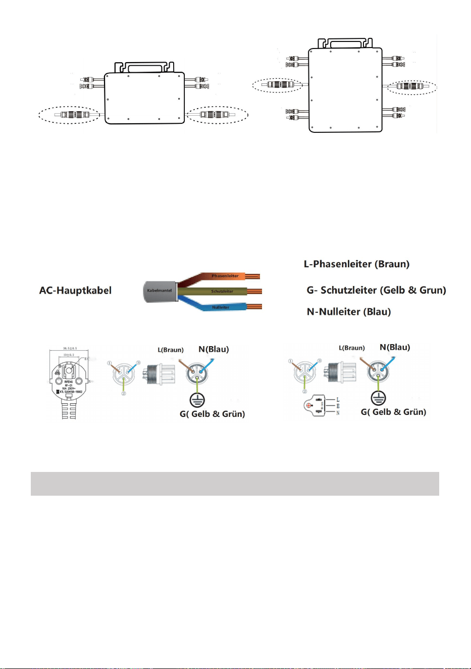
WIRING SCHEMATIC
Single phase connection method of micro inverter
GT-600/GT-800
GT-1200
- 7 -
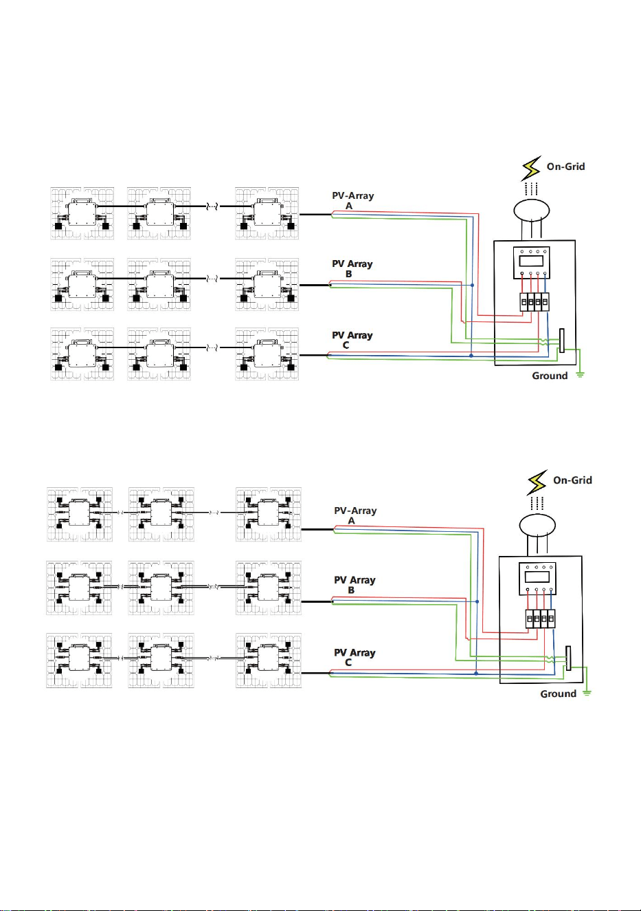
Three phase connection method of micro inverter
GT-600/GT-800
GT-1200
- 8 -
1. Precautions
Note that there is a risk of electric shock when connecting the
micro-inverter!
The micro-inverter heats up during operation! Protect yourself
accordingly from burns!
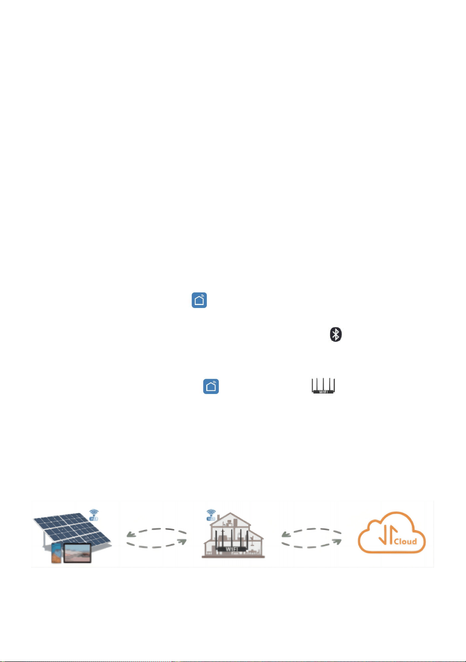
Before configuring WiFi cloud monitoring,please correctly install the
micro inverter and make it work normally.
As mart device(smartphone or tablet)with Bluetooth function and
Android or is system and a wireless network device eg.wireless router
that can provide WiFi and Internet service must be available.
To configure WLAN cloud monitoring,first switch on the Bluetooth
function of the smart device.
Make sure that your smart device uses the same WiFi network as the
micro inverter to be configured and that it can connect to wireless
network devices and access the internet in the same location of the
micro inverter.
Make sure that the distance between the wireless network device and the
micro-inverter does not exceed 20 m and that there are no or few
obstacles.
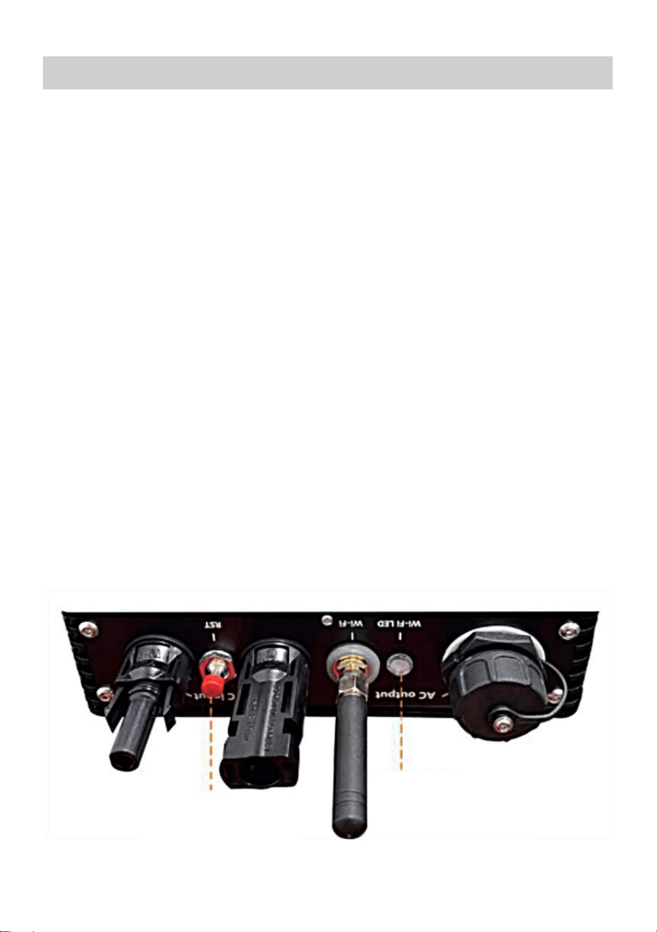
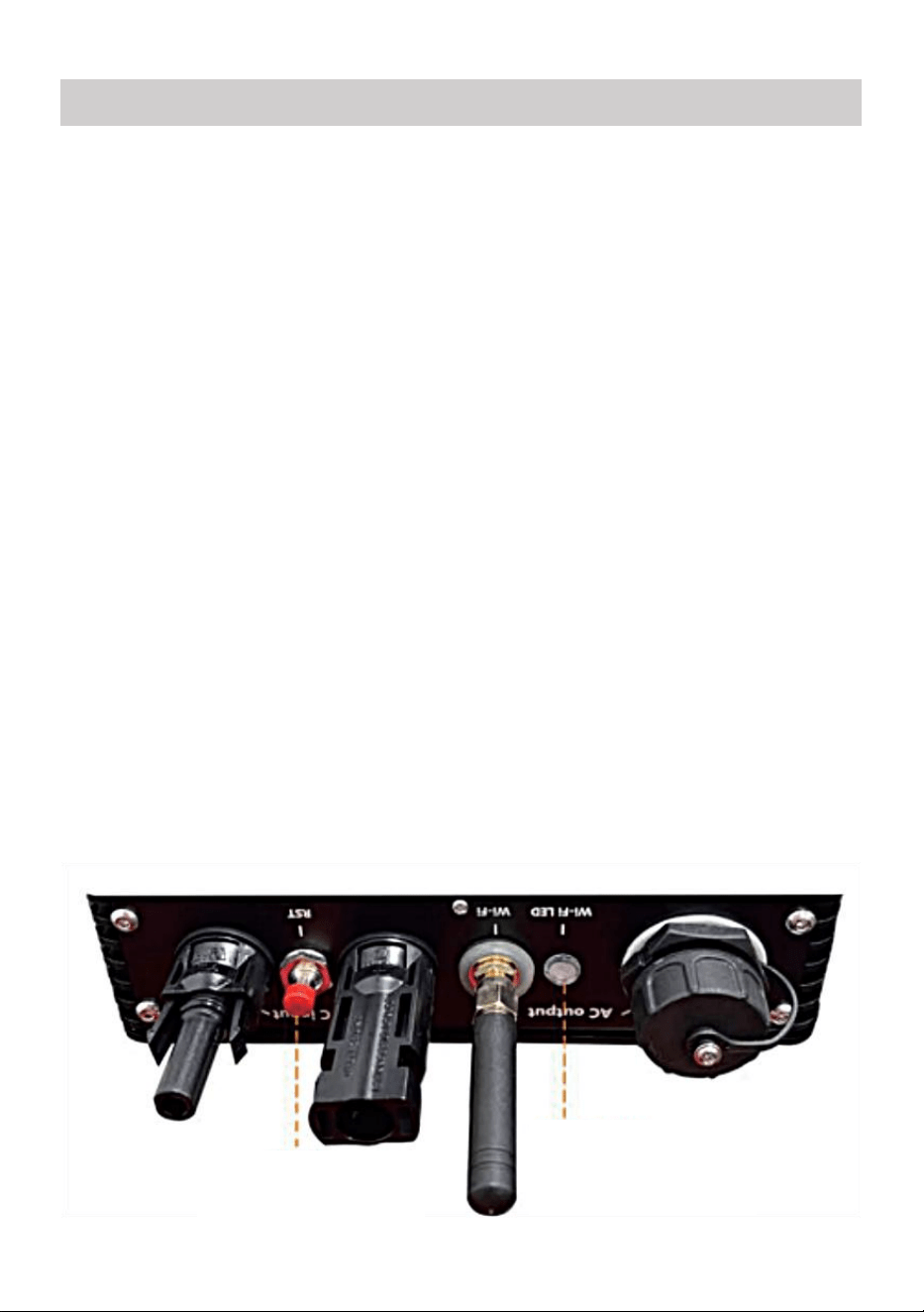
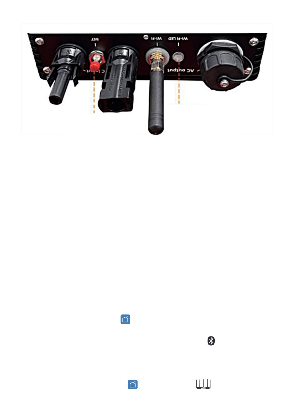
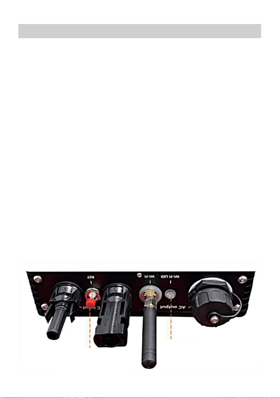
2. Hardware Description
MICRO INVERTER WIFI CLOUD MONITORING
WIFI
Set/Reset Button
WIFI Status
LED Indicator
- 9 -
3. WIFI Status LED
The blue light flashes after always on = the WiFi cloud monitoring
module is waiting for configuration.
The blue light off after always on = the WiFi cloud monitoring module
starts and enters the normal working state.
The blue light flashes = the network is not configured or the network
cannot connect to the wireless network device, or the micro inverter has
been deleted in the cloud.
No light = WiFi cloud monitoring is working normally.
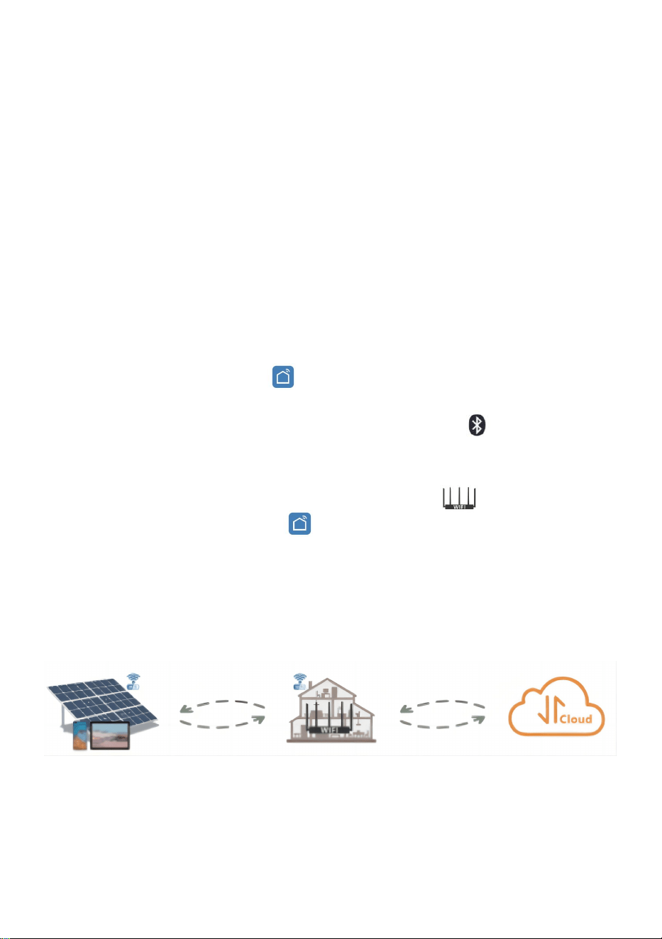
4. Preparation Before Configuration And Use
Install the micro inverter correctly and make it work normally to generate
power.
Download and install the or "Smart Life" app by searching for it in
the corresponding Android or Apple app store.
Turn on the Bluetooth function of your smart device .
Check that your wireless network device(such as wireless router) is
working properly and connected to the Internet .
Use your smart device ( or "Smart Life" App installed) at the
installation location of micro inverter to connect to the wireless network
device.If you can access the Internet normally, follow the instructions
for configuration and usage on the next page.

- 10 -
5. Configuration Steps Of WIFI Cloud Monitoring.
- 11 -
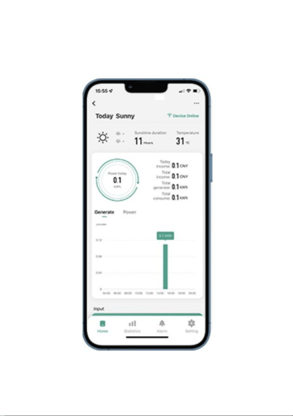
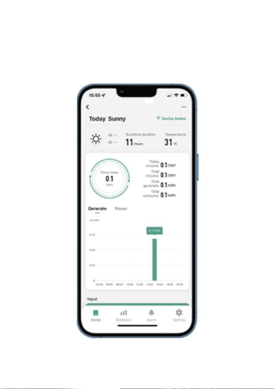
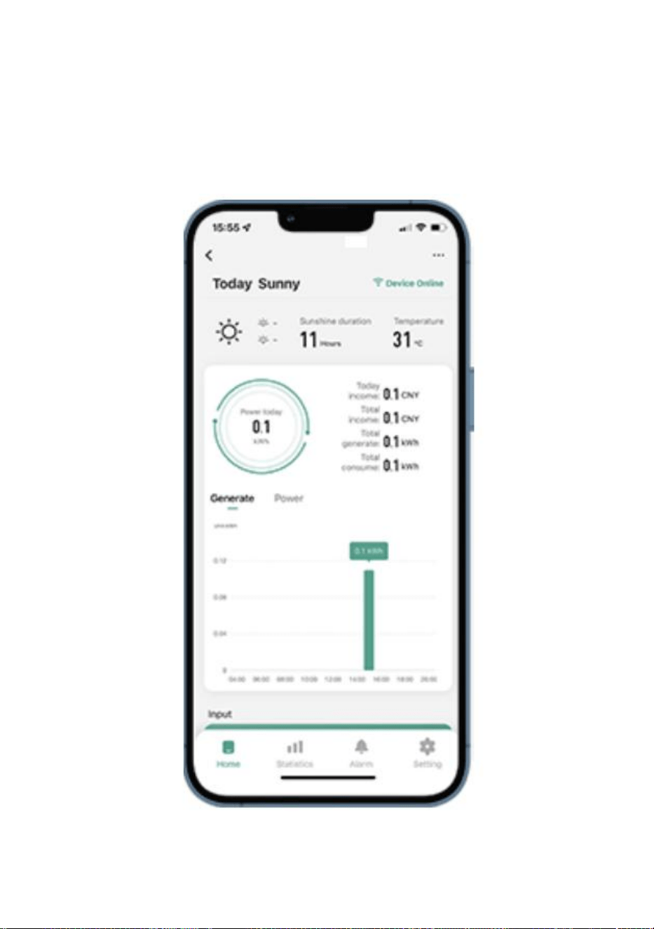
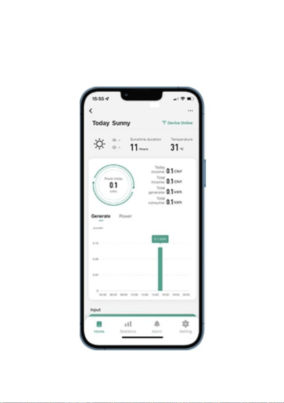
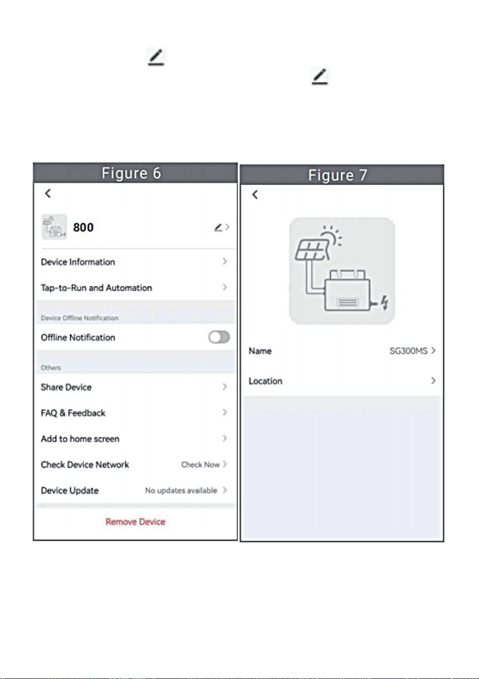
6. Usage Of WIFI Cloud Monitoring App.
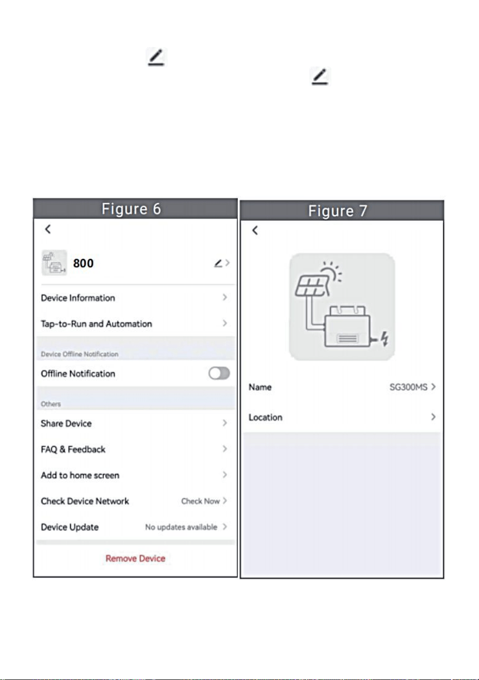
Modify Device Name
Click the device to be modified in the device list on the home page to
enter the device information details page (Figure 5).

- 12 -
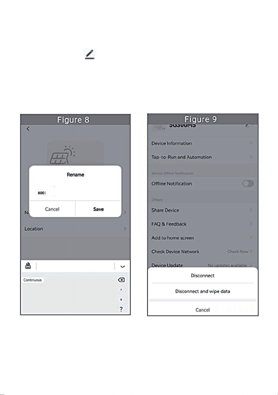
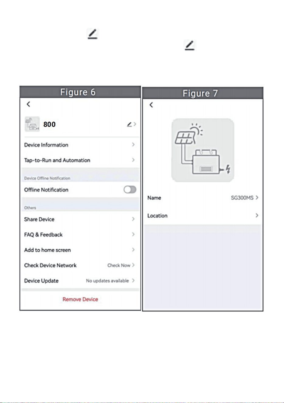
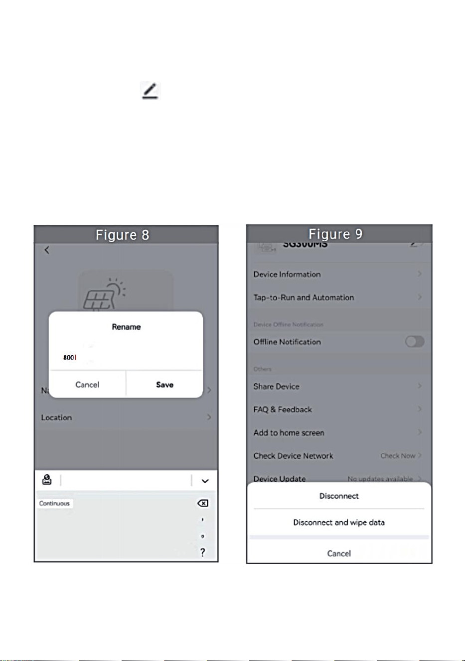
Click the button in the upper right to enter the device setting page
(Figure 6), Continue to click the upper button to the page of name
& position (Figure 7) click name item, then enter a new name and save it
(Figure 8).
- 13 -
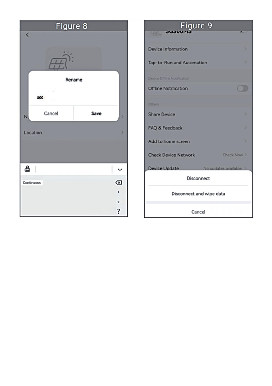
Remove Device
Click the device to be deleted in the device list on the home page to enter
the device information details page (Figure 5).
Click the button in the upper right to enter the device setting page
(Figure 6).Click "Remove Device" button below (Figure 9), click the
"Disconnect" button to remove the device or click the "Disconnect and
wipe data"button to remove the device and clear all data saved by the
device in the cloud at the same time.

- 14 -
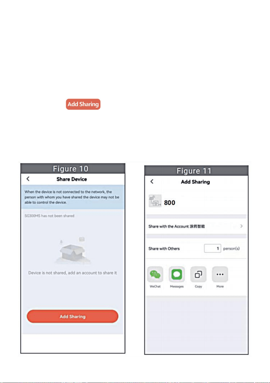
Share Device With Others
Click the device to be shared in the device list on the home page to enter
the device information details page (Figure 5).
Click the button in the upper right to enter the device setting page
(Figure 6).
Click the "Share Device" item to enter the device sharing page (Figure
10), click button to enter “Add Sharing”page (Figure 11) ,
and select best sharing way that you think it is most convenient to share
the link of micro inverter.
- 15 -
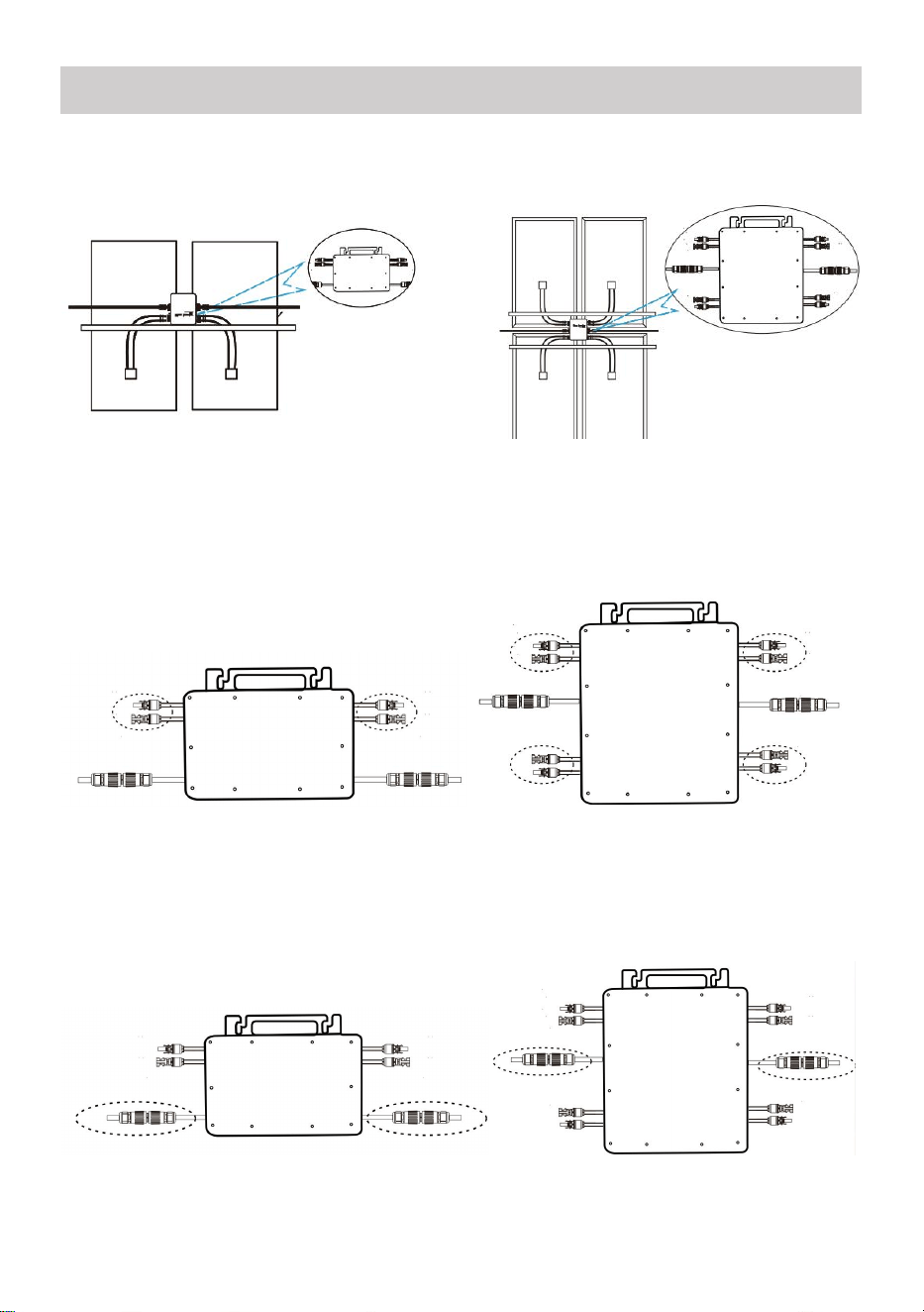
1. The installation process of fixing inverter to PV bracket with mounting
screws is as follows:
GT-600/800 GT-1200
2. Connect the DC of PV to the inverter, and pay attention to distinguish
between positive and negative, as shown below:
GT-600/800 GT-1200
3. Open the waterproof cover on the AC output side of the micro inverter,
and then connect it to the AC. As follows:
GT-600/800 GT-1200
INSTRUCTIONS FOR INSTALLATION WIRING
- 16 -
4. Repeat steps 1 to 3 to complete the installation of the micro inverter.
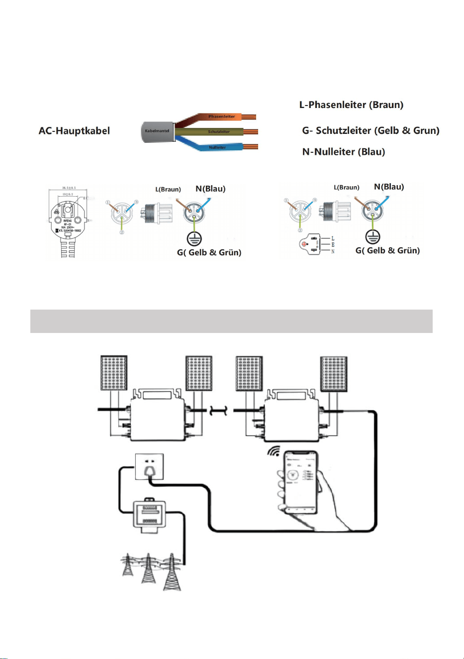
5. Connect multiple inverters through AC output cables.
6. The AC main cable is connected to the power grid.
AC230V 50Hz AC110V 60Hz
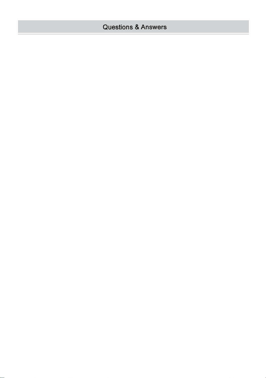
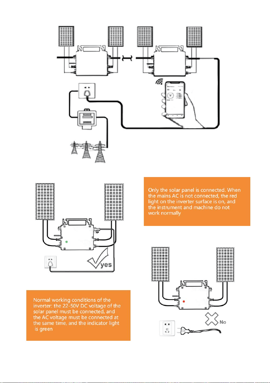
SCHEMATIC DIAGRAM OF THE COMPLETION OF THE INSTALLATION

- 17 -
GT-600/800

- 18 -
GT-1200
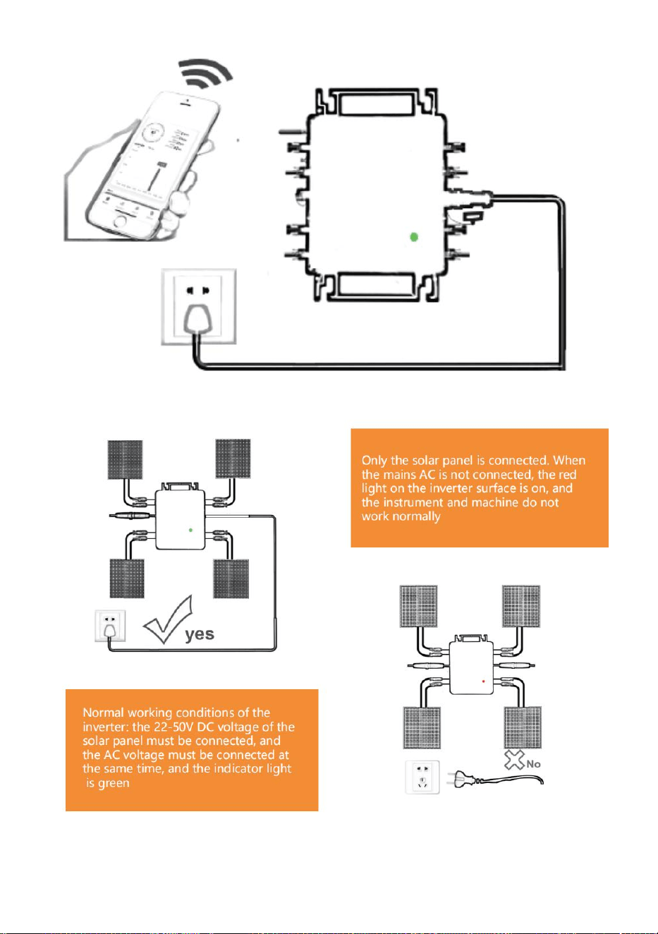
Note:
When the inverter is purchased for the first time and connected to the
mobile phone for monitoring, it is only necessary to switch on the mains AC,
the blue light beside it flashes, and the inverter can be connected through
WIFI or Bluetooth pairing. When the inverter can be controlled through the
mobile phone, it is indicated that the connection is normal.
- 19 -
1. WHAT TO DO when the Smart-App can't find the micro inverter to be
added?
Check the following points:
Check if the WiFi status indicator of the micro inverter is in the "Blue
Flashing" state.
Check if the Bluetooth function of your smart device is turned on.
Check if the signal of the wireless network is good.
If all these is the case and the inverter is still not found, press the red reset
button for more than 5 seconds to reset. After the WiFi indicator light flashes
blue again, use "Smart Life " App to reconfigure the network.
2. WHAT TO DO if I have multiple micro inverters to configure?
Install all micro inverters properly and make them work normally to
generate power, and then operate according to the configuration and using
steps. The App can search all inverters to be added at one time and
configure them at one time.
3. WHAT TO DO if the SSID of my WiFi network or the password is changed?
Please reconfigure the inverter according to the configuration and using
steps.
4. WHAT TO DO if the WiFi status indicator of the inverter goes out, but the
device displayed on the app is not online?
This means that you can connect to the wireless network device, but you
can't connect to the cloud server. It means that your wireless network
device can't connect to the Internet. Make sure that your Internet is working
properly.
5. The installation site of the inverter is temporarily not equipped
with a router and no WiFi signal?
How does App connect the inverter and detect if the inverter is working
properly?

- 20 -
You can use an idle smartphone to open the WiFi sharing of mobile
phone signal hotspot for connection, and reconfigure the network
connection after installing the router.
6. There are multiple WiFi signals around. Can we connect different
WiFi signals?
No, the WiFi connected of the micro inverter and the smart phone must
be consistent before the network can be configured.
7. Can App configure the micro inverter in different places? Can I
view data in different places?
You can't configure the micro inverter in different places, but you can
view data in different places.The inverter uploads the latest status data to
the cloud server every 3-5 minute.
8. After checking that there is no problem, the App still cannot find
the micro inverter.
Press and hold the inverter red button for more than 5 seconds to reset
the inverter.
After the WiFi indicator flashes again, use App to reconfigure the
network.
9. WHAT TO DO if I want to monitor the same inverter on two or more
smart devices?
You can share the inverter with another phone using the share device
feature.
10. Will App data be saved?
Yes, App data will be stored on cloud server. After the network is
successfully configured, you can view the data at any time and place.
11. The inverter cannot be connected to the app at night?
At night, because the solar panel does not generate power, the micro
inverter does not have any power input, so it will offline and it is impossible

- 21 -
to re-configure the network at night.
ACCESSORIES LIST
1.Operating instructions *1
2.Grid connected power cord *1
3.8mm diameter, 28mm long hex socket screw+flat washer+spring
washer+nut *2
4.5mm diameter, 13mm long hex socket screw+nut *2(600W/800W)
4mm diameter, 8mm long hex socket screw *1(1200W)
5.WiFi antenna *1

- 22 -
Manufacturer: Shanghaimuxinmuyeyouxiangongsi
Address: Shuangchenglu 803nong11hao1602A-1609shi, baoshanqu,
shanghai 200000 CN.
Imported to AUS: SIHAO PTY LTD, 1 ROKEVA STREETEASTWOOD
NSW 2122 Australia
Imported to USA: Sanven Technology Ltd., Suite 250, 9166 Anaheim Place,
Rancho Cucamonga, CA 91730
REP
EC
E-CrossStu GmbH
Mainzer Landstr.69, 60329 Frankfurt am Main.
REP
UK
YH CONSULTING LIMITED.
C/O YH Consulting Limited Office 147, Centurion House,
London Road, Staines-upon-Thames, Surrey, TW18 4AX


- 24 -
Technique Certificat d'assistance et de garantie électronique
www.vevor.com/support
MICRO-ONDULEUR
MODÈLE : GT-600/GT-800/GT-1200
We continue to be committed to provide you tools with competitive price.
"Save Half", "Half Price" or any other similar expressions used by us only represents an
estimate of savings you might benefit from buying certain tools with us compared to the major
top brands and does not necessarily mean to cover all categories of tools offered by us. You
are kindly reminded to verify carefully when you are placing an order with us if you are
actually saving half in comparison with the top major brands.

- 1 -
MODÈLE : GT-600/GT-800/GT-1200
GT-600/GT-800 GT-1200
Have product questions? Need technical support? Please feel free to
contact us:
Technical Support and E-Warranty Certificate
www.vevor.com/support
NEED HELP? CONTACT US!
This is the original instruction, please read all manual instructions
carefully before operating. VEVOR reserves a clear interpretation of our
user manual. The appearance of the product shall be subject to the
product you received. Please forgive us that we won't inform you again if
there are any technology or software updates on our product.
MICRO INVERTER
- 2 -
Avertissement - Pour réduire le risque de blessure, l'utilisateur
doit lire attentivement le manuel d'instructions.
Ce produit est soumis aux dispositions de la directive
européenne 2012/19/CE. Le symbole représentant une
poubelle à roulettes barrée indique que le produit doit faire
l'objet d'une collecte sélective des déchets dans l'Union
européenne. Cela s'applique au produit et à tous les
accessoires marqués de ce symbole. Les produits marqués
comme tels ne peuvent pas être jetés avec les déchets
ménagers normaux, mais doivent être déposés dans un point
de collecte pour le recyclage des appareils électriques et
électroniques.
AVERTISSEMENT : RISQUE DE CHOC ÉLECTRIQUE
Le produit est utilisé en combinaison avec une source d'énergie
permanente (batterie). Même si l'équipement est éteint, une source
d'énergie dangereuse
Une tension électrique peut se produire aux bornes d'entrée et/ou de sortie.
Coupez toujours l'alimentation secteur et débranchez la batterie avant
effectuer des travaux de maintenance.
Le produit ne contient aucune pièce interne réparable par l'utilisateur. Ne
retirez pas le panneau avant et ne mettez pas le produit en service tant
que tous les panneaux ne sont pas installés. Toute maintenance doit être
effectuée par du personnel qualifié.
N'utilisez jamais le produit dans des endroits où des explosions de gaz ou
de poussières pourraient se produire. Reportez-vous aux spécifications
fournies par le fabricant du produit. batterie pour vous assurer que la
batterie est adaptée à l'utilisation avec ce produit. Les instructions de
sécurité du fabricant de la batterie doivent toujours être observé.
ATTENTION : ne soulevez pas d’objets lourds sans aide.
Installation

- 3 -
Lisez les instructions d’installation avant de commencer les activités
d’installation.
Ce produit est un appareil de classe de sécurité I (fourni avec une borne de
terre pour des raisons de sécurité). Ses bornes d'entrée et/ou de sortie CA
doit être équipé d'une mise à la terre sans interruption pour des raisons de
sécurité. Un point de mise à la terre supplémentaire est situé à l'extérieur
du produit. Si l'on peut supposer que la protection de mise à la terre est
endommagée, le produit doit être mis hors service et éviter toute remise en
service accidentelle ; contacter un personnel de maintenance qualifié.
Assurez-vous que les câbles de raccordement sont équipés de fusibles et
de disjoncteurs. Ne remplacez jamais un dispositif de protection par un
composant d'un
type différent. Reportez-vous au manuel pour connaître la pièce
appropriée.
Vérifiez avant d'allumer l'appareil si la source de tension disponible est
conforme aux paramètres de configuration du produit. décrit dans le
manuel.
Assurez-vous que l'équipement est utilisé dans des conditions de
fonctionnement correctes. Ne l'utilisez jamais dans un environnement
humide ou poussiéreux.
Assurez-vous qu'il y a toujours suffisamment d'espace libre autour du
produit pour la ventilation et que les ouvertures de ventilation ne sont pas
obstruées.
Installez le produit dans un environnement résistant à la chaleur. Veillez
donc à ce qu'il ne soit pas exposé à des produits chimiques, des pièces en
plastique, des rideaux ou autres textiles, etc.
à proximité immédiate de l'équipement.
Transport et stockage
Lors du stockage ou du transport du produit, assurez-vous que
l'alimentation secteur et les câbles de la batterie sont débranchés.
Aucune responsabilité ne peut être acceptée pour les dommages survenus
pendant le transport si l'équipement n'est pas transporté dans son
emballage d'origine.

- 4 -
Conserver le produit dans un environnement sec ; la température de
stockage doit être comprise entre –40°C et 65 ° C.
Reportez-vous au manuel du fabricant de la batterie pour obtenir des
informations sur le transport, le stockage, la charge, la recharge et la mise
au rebut de la batterie.
- 5 -
SPECIFICATIONS
Tu es Bienvenue pour choisir nos produits d'onduleurs solaires connectés au
micro-réseau .
Données de spécification
Modèle
GT-600
GT-800
GT-1200
Données d'entrée (DC, PV)
Nombre de connecteurs d'entrée
MC4
2 ensembles
4 ensembles
Plage de tension de
fonctionnement
DC18V-50V
Courant d'entrée maximal
12A*2
14A*2
16A*2
Données de sortie (CA)
Type de réseau monophasé
CA 230 V
CA 230 V
CA ou 230 V CA
Puissance de sortie maximale
600 W
800 W
1200 W
Courant de sortie nominal
2,6 A
3,5 A
10,9 A ou 5,2 A
Tension de sortie nominale
CA 230 V
CA 230 V
CA ou 230 V CA
Plage de fréquence de sortie
50 Hz
50 Hz
60 Hz ou 50 Hz
Facteur de puissance
≥ 0,99 %
Distorsion harmonique totale
Distorsion harmonique < 5 %
Nombre maximal d'unités par
succursale
@230VAC : 4 unités
@230VAC : 3 unités
@ 110 VAC : 2 unités Ou @ 230 VAC :
3 unités
Efficacité maximale
95%
Efficacité nominale du MPPT
99,5%
Consommation d'énergie
nocturne
≤1W
Données mécaniques
Plage de température ambiante
de fonctionnement
-40℃ à +65℃
Plage de température de
stockage
-40°C à +85°C
Dimensions (L x H x P)
305 * 186 * 44 mm
490 * 254 * 50 mm
Niveau d'étanchéité
IP67
IP65/IP67
(Veuillez vous
IP67
- 6 -
référer aux
informations
figurant sur la
plaque
signalétique du
produit)
Communication
WIFI (Surveillance du Cloud)
Fonctions de protection
Protection des îlots isolés, protection contre la tension
Protection de fréquence
Protection de température, protection de courant, etc.
INSTALLATION SCHEMATIC
Méthode d'assemblage parallèle monophasé de micro onduleur
GT-600
4. @Réseau monophasé 230 V Maximum 4 unités 600W Micro onduleurs par
branche.
5. La puissance d'entrée CC maximale de chaque onduleur est de 600 W (la
puissance de sortie maximale du module PV).
la puissance est de 2x300W) .
6. Le VOC des modules PV ne doit pas être supérieur à la tension d'entrée CC
maximale
de Micro onduleurs .
GT-800

- 7 -
4. @Réseau monophasé 230 V Maximum 3 unités 8 00W Micro onduleurs par
branche.
5. La puissance d'entrée CC maximale de chaque onduleur est de 8 00 W (la
puissance de sortie maximale du module PV).
la puissance est de 2x 4 00W) .
6. Le VOC des modules PV ne doit pas être supérieur à la tension d'entrée CC
maximale
de Micro onduleurs .

- 8 -
GT-1200
4. Réseau monophasé 110 V Maximum 2 unités ou réseau monophasé 230 V
Maximum 3 unités 12 00W Micro onduleurs par branche.
5. La puissance d'entrée CC maximale de chaque onduleur est de 12 00 W (la
puissance de sortie maximale du module PV).
la puissance est de 2x 6 00W) .
6. Le VOC des modules PV ne doit pas être supérieur à la tension d'entrée CC
maximale
de Micro onduleurs .
WIRING SCHEMATIC
Méthode de connexion monophasée du micro-onduleur
GT-600/GT-800
GT-1200

- 9 -
Méthode de connexion triphasée du micro-onduleur
GT-600/GT-800
GT-1200
- 10 -
7. Précautions
Attention, il existe un risque de choc électrique lors du raccordement du
micro-onduleur !
Le micro-onduleur chauffe pendant le fonctionnement ! Protégez-vous
en conséquence des brûlures !
Avant de configurer la surveillance du cloud WiFi, veuillez installer
correctement le micro-onduleur et le faire fonctionner normalement .
Comme Un appareil mobile (smartphone ou tablette) avec fonction
Bluetooth et Android ou un système et un périphérique réseau sans fil,
par exemple un routeur sans fil pouvant fournir un service WiFi et
Internet, doivent être disponibles .
Pour configurer la surveillance du cloud WLAN, activez d'abord la
fonction Bluetooth de l'appareil intelligent.
Assurez-vous que votre appareil intelligent utilise le même réseau WiFi
que le micro-onduleur à configurer et qu'il peut se connecter aux
périphériques réseau sans fil et accéder à Internet au même
emplacement que le micro-onduleur .
Assurez-vous que la distance entre le périphérique réseau sans fil et le
micro-onduleur ne dépasse pas 20 m et qu'il n'y a pas ou peu
d'obstacles.
8. Description du matériel
MICRO INVERTER WIFI CLOUD MONITORING
WIFI
Set/Reset Button
WIFI Status
LED Indicator
- 11 -
9. Voyant d'état du Wi-Fi
Le voyant bleu clignote après avoir toujours été allumé = le module de
surveillance cloud WiFi est en attente de configuration.
Le voyant bleu s'éteint après avoir toujours été allumé = le module de
surveillance cloud WiFi démarre et entre dans l'état de fonctionnement
normal.
Le voyant bleu clignote = le réseau n'est pas configuré ou le réseau ne
peut pas se connecter au périphérique réseau sans fil, ou le
micro-onduleur a été supprimé dans le cloud.
Pas de lumière = la surveillance du cloud WiFi fonctionne normalement .
10. Préparation avant la configuration et l'utilisation
Installez correctement le micro-onduleur et faites-le fonctionner
normalement pour générer de l'énergie.
Téléchargez et installez le ou Téléchargez l'application « Smart Life »
en la recherchant dans l'App Store Android ou Apple correspondant.
Activez la fonction Bluetooth de votre appareil intelligent .
Vérifiez que votre périphérique réseau sans fil (tel qu'un routeur sans fil)
fonctionne correctement et est connecté à Internet .
Utilisez votre appareil intelligent ( ou « Vie intelligente » (Application
installée) à l'emplacement d'installation du micro-onduleur pour se
connecter au périphérique réseau sans fil. Si vous pouvez accéder
normalement à Internet , suivez les instructions de configuration et
d'utilisation sur la page suivante.

- 12 -
11. Étapes de configuration de la surveillance du cloud WIFI .
- 13 -
12. Utilisation de l'application de surveillance du cloud WIFI .
Modifier le nom de l'appareil
Cliquez sur l'appareil à modifier dans la liste des appareils sur la page
d'accueil pour accéder à la page de détails des informations sur
l'appareil (Figure 5).
- 14 -
Cliquez sur le bouton en haut à droite pour accéder à la page de
configuration de l'appareil (Figure 6), continuez à cliquer sur le bouton
supérieur sur la page du nom et du poste (Figure 7), cliquez sur
l'élément Nom, puis entrez un nouveau nom et enregistrez-le (Figure 8).
- 15 -
Supprimer l'appareil
Cliquez sur l'appareil à supprimer dans la liste des appareils sur la page
d'accueil pour saisir les informations de l'appareil page de détails
(Figure 5).
Cliquez sur le bouton en haut à droite pour accéder à la page de
configuration de l'appareil (Figure 6).Cliquez sur le bouton « Supprimer
l'appareil » ci-dessous (Figure 9), cliquez sur le bouton « Déconnecter »
pour retirez l'appareil ou cliquez sur le bouton « Déconnecter et effacer
les données » pour supprimer l'appareil et effacer toutes les données
enregistrées par l'appareil dans le cloud en même temps.

- 16 -
Partager l'appareil avec d'autres
Cliquez sur l’appareil à partager dans la liste des appareils sur la page d’
accueil pour accéder à la page de détails des informations sur l’appareil
(Figure 5).
Cliquez sur le bouton en haut à droite pour accéder au page de
configuration de l'appareil (Figure 6).
Cliquez sur l'élément « Partager l'appareil » pour accéder à l'appareil
page de partage (Figure 10) , cliquez sur bouton pour
accéder à la page « Ajouter un partage » (Figure 11) et sélectionnez la
meilleure façon de partager qui vous semble la plus adaptée pratique
pour partager le lien du micro onduleur.

- 17 -
7. Le processus d'installation de la fixation de l'onduleur au support PV
avec montage
les vis sont les suivantes :
INSTRUCTIONS FOR INSTALLATION WIRING
- 18 -
GT-600/800 GT-1200
8. Connectez le courant continu du PV à l'onduleur et faites attention à bien
distinguer
entre positif et négatif, comme indiqué ci-dessous :
GT-600/800 GT-1200
9. Ouvrez le couvercle étanche du côté sortie CA du micro-onduleur,
et puis connectez-le au secteur. Comme suit :
GT-600/800 GT-1200
10. Répétez les étapes 1 à 3 pour terminer l’installation du micro-onduleur.
11. Connectez plusieurs onduleurs via des câbles de sortie CA.
12. Le câble principal CA est connecté au réseau électrique.
- 19 -
CA 230 V 50 Hz CA 110 V 60 Hz
SCHEMATIC DIAGRAM OF THE COMPLETION OF THE INSTALLATION
- 20 -
GT-600/800

- 21 -
GT-1200
Note:
Lorsque l'onduleur est acheté pour la première fois et connecté au réseau
Pour la surveillance par téléphone portable, il suffit d'allumer le secteur, le
voyant bleu à côté clignote et l'onduleur peut être connecté via WIFI ou
couplage Bluetooth. Lorsque l'onduleur peut être contrôlé via le téléphone
portable, cela indique que la connexion est normale.
- 22 -
12. QUE FAIRE lorsque l'application Smart-App ne parvient pas à trouver le
micro-onduleur à installer
ajouté?
Vérifiez les points suivants :
Vérifiez si l'indicateur d'état WiFi du micro-onduleur est dans l'état
« clignotant bleu » .
Vérifiez si la fonction Bluetooth de votre appareil intelligent est activée .
Vérifiez si le signal du réseau sans fil est bon.
Si tout cela est le cas et que l'onduleur n'est toujours pas trouvé, appuyez
sur le bouton de réinitialisation rouge pendant plus de 5 secondes pour
Réinitialiser. Une fois que le voyant WiFi clignote à nouveau en bleu, utilisez
l'application « Smart Life » pour reconfigurer le réseau.
13. QUE FAIRE si j'ai plusieurs micro-onduleurs à configurer ?
Installez correctement tous les micro-onduleurs et faites-les fonctionner
normalement pour générer de l'électricité, puis fonctionne selon la
configuration et les étapes d'utilisation. L'application peut rechercher tous
les onduleurs à ajouter en une seule fois temps et les configurer en même
temps.
14. QUE FAIRE si le SSID de mon réseau WiFi ou le mot de passe est
modifié ?
Veuillez reconfigurer l'onduleur selon la configuration et les étapes à
suivre.
15. QUE FAIRE si l'indicateur d'état WiFi de l'onduleur s'éteint, mais que
appareil affiché sur le l'application n'est pas en ligne ?
Cela signifie que vous pouvez vous connecter au périphérique réseau
sans fil, mais vous ne pouvez pas vous connecter au cloud serveur. Cela
signifie que votre périphérique réseau sans fil ne peut pas se connecter à
Internet. Assurez-vous que votre Internet fonctionne correctement.

- 23 -
16. Le lieu d'installation de l'onduleur n'est temporairement pas
équipé d'un routeur et pas de signal WiFi ?
Comment l'application connecte-t-elle l'onduleur et détecte-t-elle si
l'onduleur fonctionne correctement ?
Vous pouvez utiliser un smartphone inactif pour ouvrir le partage WiFi
du point d'accès du signal du téléphone mobile pour connexion et
reconfigurer la connexion réseau après l'installation du routeur.
17. Il y a plusieurs signaux WiFi autour. Pouvons-nous connecter
différents signaux WiFi ?
Non, le WiFi connecté du micro-onduleur et du smartphone doit être
cohérent avant que le réseau puisse être configuré.
18. L'application peut-elle configurer le micro-onduleur à différents
endroits ? Puis-je consulter les données à différents endroits ?
Vous ne pouvez pas configurer le micro-onduleur à différents endroits,
mais vous pouvez afficher les données à différents endroits. L'onduleur
télécharge les dernières données d'état sur le serveur cloud toutes les 3 à
5 minutes.
19. Après avoir vérifié qu'il n'y a pas de problème, l'application ne
parvient toujours pas à trouver le micro-onduleur.
Appuyez sur le bouton rouge de l'onduleur et maintenez-le enfoncé
pendant plus de 5 secondes pour réinitialiser l'onduleur.
Une fois que l'indicateur WiFi clignote à nouveau, utilisez l'application
pour reconfigurer le réseau.
20. QUE FAIRE si je souhaite surveiller le même onduleur sur deux
ou plusieurs appareils intelligents ?
Vous pouvez partager l'onduleur avec un autre téléphone à l'aide de la
fonction de partage d'appareil.
21. Les données de l’application seront-elles enregistrées ?

- 24 -
Oui, les données de l'application seront stockées sur un serveur cloud.
Une fois le réseau correctement configuré, vous pouvez consulter les
données à tout moment et en tout lieu.
22. L'onduleur ne peut pas être connecté à l'application la nuit ?
La nuit, comme le panneau solaire ne produit pas d'électricité, le
micro-onduleur n'a pas d' entrée d'alimentation, il sera donc hors ligne et il
sera impossible de reconfigurer le réseau la nuit.
ACCESSORIES LIST
6.Mode d'emploi *1
7.Cordon d'alimentation connecté au réseau *1
8.Vis à six pans creux de 8 mm de diamètre et 28 mm de long + rondelle
plate + ressort
rondelle + écrou * 2
9.Vis à six pans creux de 5 mm de diamètre et 13 mm de long + écrou * 2
(600 W/800 W)
Vis à six pans creux de 4 mm de diamètre et 8 mm de long *1 (1200 W)
10.Antenne WiFi *1

- 25 -
Fabricant : Shanghaimuxinmuyeyouxiangongsi
Adresse : Shuangchenglu 803nong11hao1602A-1609shi, baoshanqu,
Shanghai 200000 CN.
Importé en Australie : SIHAO PTY LTD, 1 ROKEVA STREET, ASTWOOD
NSW 2122 Australie
Importé aux États-Unis : Sanven Technology Ltd., Suite 250, 9166
Anaheim Place, Rancho Cucamonga, CA 91730
REP
EC
E-CrossStu GmbH
Mainzer Landstr.69, 60329 Frankfurt am Main.
REP
UK
YH CONSULTING LIMITED.
C/O YH Consulting Limited Office 147, Centurion House,
London Road, Staines-upon-Thames, Surrey, TW18 4AX


- 27 -
Technisch Support und E-Garantie-Zertifikat
www.vevor.com/support
MIKRO-WECHSELRICHTER
MODELL: GT-600/GT-800/GT-1200
We continue to be committed to provide you tools with competitive price.
"Save Half", "Half Price" or any other similar expressions used by us only represents an
estimate of savings you might benefit from buying certain tools with us compared to the major
top brands and does not necessarily mean to cover all categories of tools offered by us. You
are kindly reminded to verify carefully when you are placing an order with us if you are
actually saving half in comparison with the top major brands.

- 1 -
MODELL: GT-600/GT-800/GT-1200
GT-600/GT-800 GT-1200
Have product questions? Need technical support? Please feel free to
contact us:
Technical Support and E-Warranty Certificate
www.vevor.com/support
NEED HELP? CONTACT US!
This is the original instruction, please read all manual instructions
carefully before operating. VEVOR reserves a clear interpretation of our
user manual. The appearance of the product shall be subject to the
product you received. Please forgive us that we won't inform you again if
there are any technology or software updates on our product.
MICRO INVERTER

- 2 -
Warnung: Um das Verletzungsrisiko zu verringern, muss der
Benutzer die Bedienungsanleitung sorgfältig lesen.
Dieses Produkt unterliegt den Bestimmungen der europäischen
Richtlinie 2012/19/EU. Das Symbol einer durchgestrichenen
Mülltonne weist darauf hin, dass das Produkt in der
Europäischen Union einer getrennten Müllentsorgung
unterliegt. Dies gilt für das Produkt und alle mit diesem Symbol
gekennzeichneten Zubehörteile. So gekennzeichnete Produkte
dürfen nicht im normalen Hausmüll entsorgt werden, sondern
müssen an einer Sammelstelle für das Recycling von
elektrischen und elektronischen Geräten abgegeben werden.
WARNUNG: STROMSCHLAGGEFAHR
Das Produkt wird in Kombination mit einer permanenten Energiequelle
(Batterie) verwendet. Auch wenn das Gerät ausgeschaltet ist,
An den Eingangs- und/oder Ausgangsklemmen kann elektrische
Spannung auftreten. Schalten Sie immer die Wechselstromversorgung aus
und trennen Sie die Batterie ab, bevor Sie
Durchführen von Wartungsarbeiten.
Das Produkt enthält keine internen Teile, die vom Benutzer gewartet
werden können. Entfernen Sie die Frontplatte nicht und nehmen Sie das
Produkt erst in Betrieb, wenn alle Platten montiert sind. Alle
Wartungsarbeiten sollten von qualifiziertem Personal durchgeführt werden.
Verwenden Sie das Produkt nicht an Orten, an denen es zu Gas- oder
Staubexplosionen kommen kann. Beachten Sie die Angaben des
Herstellers des Batterie, um sicherzustellen, dass die Batterie für die
Verwendung mit diesem Produkt geeignet ist. Die Sicherheitshinweise des
Batterieherstellers sollten immer beobachtet.
WARNUNG: Heben Sie keine schweren Gegenstände ohne Hilfe.
Installation
Lesen Sie die Installationsanweisungen, bevor Sie mit den
Installationsarbeiten beginnen.

- 3 -
Dieses Produkt ist ein Gerät der Sicherheitsklasse I (aus
Sicherheitsgründen mit Erdungsklemme ausgestattet). Seine
AC-Eingangs- und/oder Ausgangsklemmen muss aus Sicherheitsgründen
mit einer unterbrechungsfreien Erdung versehen sein. Ein zusätzlicher
Erdungspunkt befindet sich an der Außenseite des Produkts. Wenn davon
auszugehen ist, dass der Erdungsschutz beschädigt ist, sollte das Produkt
außer Betrieb genommen und gegen unbeabsichtigte
Wiederinbetriebnahme gesichert ist; qualifiziertes Wartungspersonal
kontaktieren.
Stellen Sie sicher, dass die Anschlusskabel mit Sicherungen und
Schutzschaltern ausgestattet sind. Ersetzen Sie niemals eine
Schutzvorrichtung durch eine Komponente eines
anderer Typ. Das richtige Teil finden Sie im Handbuch.
Prüfen Sie vor dem Einschalten, ob die verfügbare Spannungsquelle mit
den Konfigurationseinstellungen des Produkts übereinstimmt, wie im
Handbuch beschrieben.
Stellen Sie sicher, dass das Gerät unter den richtigen
Betriebsbedingungen eingesetzt wird. Betreiben Sie es niemals in nasser
oder staubiger Umgebung.
Stellen Sie sicher, dass rund um das Produkt immer ausreichend Freiraum
zur Belüftung vorhanden ist und dass die Belüftungsöffnungen nicht
blockiert sind.
Installieren Sie das Produkt in einer hitzegeschützten Umgebung. Achten
Sie daher darauf, dass sich keine Chemikalien, Plastikteile, Vorhänge oder
andere Textilien usw. im Gerät befinden.
in unmittelbarer Nähe des Gerätes.
Transport und Lagerung
Stellen Sie bei der Lagerung oder dem Transport des Produkts sicher,
dass die Netzstrom- und Batteriekabel getrennt sind.
Für Transportschäden kann keine Haftung übernommen werden, wenn
das Gerät nicht in der Originalverpackung transportiert wird.
Lagern Sie das Produkt trocken; die Lagertemperatur sollte zwischen
–40°C und 65 ° C liegen.

- 4 -
Informationen zu Transport, Lagerung, Laden, Nachladen und Entsorgung
der Batterie finden Sie im Handbuch des Batterieherstellers.
- 5 -
SPECIFICATIONS
Du bist Willkommen bei unseren netzgekoppelten
Mikro-Solarwechselrichterprodukten .
Spezifikationsdaten
Modell
GT-600
GT-800
GT-1200
Eingangsdaten (DC, PV)
Anzahl der MC4-Eingangsstecker
2 Sätze
4 Sätze
Betriebsspannungsbereich
Gleichstrom 18 V bis 50 V
Maximaler Eingangsstrom
12A*2
14A*2
16A*2
Ausgabedaten (AC)
Einphasiger Netztyp
Wechselstrom
230 V
Wechselstrom
230 V
AC 110 V oder AC
230 V
Maximale Ausgangsleistung
600 W
800 W
1200 W
Nennausgangsstrom
2,6 A
3,5 A
10,9 A oder 5,2 A
Nominale Ausgangsspannung
Wechselstrom
230 V
Wechselstrom
230 V
AC 110 V oder AC
230 V
Ausgangsfrequenzbereich
50 Hz
50 Hz
60 Hz oder 50 Hz
Leistungsfaktor
≥0,99 %
Gesamte harmonische Verzerrung
Klirrfaktor < 5 %
Maximale Einheiten pro Zweigstelle
@230VAC: 4
Einheiten
@230VAC: 3
Einheiten
@ 110 VAC: 2 Einheiten Oder
@230 VAC: 3 Einheiten
Höchste Effizienz
95 %
Nominale MPPT-Effizienz
99,5 %
Stromverbrauch nachts
≤1W
Mechanische Daten
Betriebsumgebungstemperaturbereich
-40℃ bis +65℃
Lagertemperaturbereich
-40°C bis +85°C
Abmessungen (B*H*T)
305 * 186 * 44 mm
490 * 254 * 50 mm
Wasserdichtigkeit
IP67
IP65/IP67
(Bitte
beachten Sie
die Angaben
auf dem
Typenschild
IP67
- 6 -
des Produkts)
Kommunikation
WIFI (Cloud-Überwachung)
Schutzfunktionen
Isolierter Inselschutz, Spannungsschutz
Frequenzschutz
Temperaturschutz, Stromschutz usw.
INSTALLATION SCHEMATIC
Einphasige Parallelmontagemethode von Mikro Wechselrichter
GT-600
7. @Einphasiges 230V Netz Maximal 4 Einheiten 600W Micro Wechselrichter pro
Zweig.
8. Die maximale DC-Eingangsleistung jedes Wechselrichters beträgt 600 W (die
maximale Leistung des PV-Moduls
Leistung beträgt 2x300W) .
9. Der VOC von PV-Modulen sollte nicht größer sein als die maximale
DC-Eingangsspannung
von Micro Wechselrichter .
GT-800
7. @Einphasiges 230V Netz Maximal 3 Einheiten 8 00W Micro Wechselrichter pro
Zweig.

- 7 -
8. Die maximale DC-Eingangsleistung jedes Wechselrichters beträgt 8 00W (die
maximale Leistung des PV-Moduls
Leistung beträgt 2x 4,00W ) .
9. Der VOC von PV-Modulen sollte nicht größer sein als die maximale
DC-Eingangsspannung
von Micro Wechselrichter .

- 8 -
GT-1200
7. @Einphasiges 110 V Netz Maximal 2 Einheiten oder @Einphasiges 230-V-Netz
Maximal 3 Einheiten 12 00W Micro Wechselrichter pro Zweig.
8. Die maximale DC-Eingangsleistung jedes Wechselrichters beträgt 12 00W (die
maximale Leistung des PV-Moduls
Leistung beträgt 2x 600W ) .
9. Der VOC von PV-Modulen sollte nicht größer sein als die maximale
DC-Eingangsspannung
von Micro Wechselrichter .
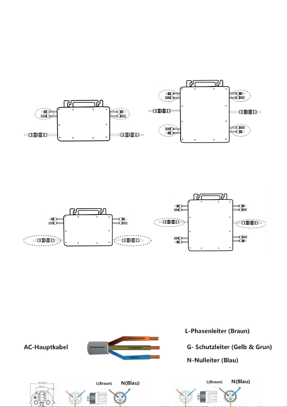
WIRING SCHEMATIC
Einphasige Anschlussmethode des Mikro-Wechselrichters
GT-600/GT-800
GT-1200

- 9 -
Dreiphasige Anschlussmethode des Mikro-Wechselrichters
GT-600/GT-800
GT-1200

- 10 -
13. Vorsichtsmaßnahmen
Beachten Sie, dass beim Anschluss des Mikro-Wechselrichters die
Gefahr eines Stromschlags besteht!
Der Mikro-Wechselrichter erwärmt sich während des Betriebs! Schützen
Sie sich
vor Verbrennungen schützen !
Bevor Sie die WiFi-Cloud-Überwachung konfigurieren, installieren Sie
bitte den Mikro-Wechselrichter korrekt und dafür sorgen, dass es
normal funktioniert .
Als Es muss ein Smartgerät (Smartphone oder Tablet) mit
Bluetooth-Funktion und Android- oder IS -System sowie ein drahtloses
Netzwerkgerät (z. B. ein WLAN-Router) verfügbar sein, das WLAN und
Internetdienste bereitstellen kann .
Um die WLAN-Cloud-Überwachung zu konfigurieren, schalten Sie zuerst
die Bluetooth-Funktion des Smart-Geräts ein.
Stellen Sie sicher, dass Ihr Smart-Gerät dasselbe WLAN-Netzwerk
verwendet wie der zu konfigurierende Mikro-Wechselrichter und dass es
eine Verbindung zu drahtlosen Netzwerkgeräten herstellen und am
selben Standort wie der Mikro-Wechselrichter auf das Internet zugreifen
kann .
Stellen Sie sicher, dass der Abstand zwischen dem drahtlosen
Netzwerkgerät und dem Mikro-Wechselrichter 20 m nicht überschreitet
und dass keine oder nur wenige Hindernisse vorhanden sind.
14. Hardwarebeschreibung
MICRO INVERTER WIFI CLOUD MONITORING
- 11 -
15. WLAN-Status-LED
Das blaue Licht blinkt nach „ Dauerhaft an “ = das
WiFi-Cloud-Überwachungsmodul wartet auf die Konfiguration.
Das blaue Licht ist aus, nachdem es immer an war = das
WiFi-Cloud-Überwachungsmodul startet und wechselt in den normalen
Arbeitszustand.
Das blaue Licht blinkt = das Netzwerk ist nicht konfiguriert oder das
Netzwerk kann keine Verbindung zum drahtlosen Netzwerkgerät
herstellen oder der Mikro-Wechselrichter wurde aus der Cloud gelöscht.
Kein Licht = Die WiFi-Cloud-Überwachung funktioniert normal .
16. Vorbereitung vor Konfiguration und Verwendung
Installieren Sie den Mikrowechselrichter ordnungsgemäß und sorgen Sie
dafür, dass er normal funktioniert und Strom erzeugt.
Laden Sie die oder Laden Sie die App „Smart Life“ herunter, indem
Sie im entsprechenden Android- oder Apple-App-Store danach suchen.
Schalten Sie die Bluetooth-Funktion Ihres Smart-Geräts ein .
Überprüfen Sie, ob Ihr drahtloses Netzwerkgerät (z. B. WLAN-Router)
ordnungsgemäß funktioniert und mit dem Internet verbunden ist .
Verwenden Sie Ihr Smartgerät ( oder "Intelligentes Leben" App
WIFI
Set/Reset Button
WIFI Status
LED Indicator

- 12 -
installiert) am Installationsort des Mikro-Wechselrichters, um eine
Verbindung zum drahtlosen Netzwerkgerät herzustellen. Wenn Sie
normal auf das Internet zugreifen können , folgen Sie den Anweisungen
zur Konfiguration und Verwendung auf der nächsten Seite.

- 13 -
17. Konfigurationsschritte der WIFI-Cloud-Überwachung .
- 14 -
18. Verwendung der WIFI-Cloud-Überwachungs-App .
Gerätenamen ändern
Klicken Sie in der Geräteliste auf der Startseite auf das zu ändernde
Gerät, um die Detailseite mit den Geräteinformationen aufzurufen
(Abbildung 5).
- 15 -
Klicken Sie auf die Schaltfläche oben rechts, um die
Geräteeinstellungsseite aufzurufen (Abbildung 6), klicken Sie weiter auf
die obere Schaltfläche Zur Seite „Name und Position“ (Abbildung
7) klicken Sie auf „ Element benennen“, geben Sie dann einen neuen
Namen ein und speichern Sie ihn (Abbildung 8).

- 16 -
Gerät entfernen
Klicken Sie in der Geräteliste auf der Startseite auf das zu löschende
Gerät, um die Geräteinformationen einzugeben Detailseite (Abbildung
5).
Klicken Sie auf die Schaltfläche oben rechts, um die
Geräteeinstellungsseite aufzurufen (Abbildung 6). Klicken Sie unten auf
die Schaltfläche „Gerät entfernen“ (Abbildung 9), klicken Sie auf die
Schaltfläche „Trennen“, um Entfernen Sie das Gerät oder klicken Sie
auf die Schaltfläche „Trennen und Daten löschen“ , um das Gerät zu
entfernen und gleichzeitig alle vom Gerät in der Cloud gespeicherten
Daten zu löschen.
- 17 -
- 18 -
Gerät mit anderen teilen
Klicken Sie in der Geräteliste auf der Startseite auf das freizugebende
Gerät, um die Detailseite mit den Geräteinformationen aufzurufen
(Abbildung 5).
Klicken Sie auf die Schaltfläche oben rechts, um die
Geräteeinstellungsseite (Abbildung 6).
Klicken Sie auf das Element „Gerät freigeben“, um das Gerät aufzurufen
(Abbildung 10) , klicken Sie auf Taste um zur Seite „
Freigabe hinzufügen “ zu gelangen (Abbildung 11) und Wählen Sie die
beste Freigabemethode aus, die Ihrer Meinung nach praktisch, um den
Link des Mikro-Wechselrichters zu teilen.
- 19 -
13. Der Installationsprozess der Befestigung des Wechselrichters an der
PV-Halterung mit Montage
Schrauben ist wie folgt:
GT-600/800 GT-1200
14. Schließen Sie den Gleichstrom der PV-Anlage an den Wechselrichter an
und achten Sie auf die Unterscheidung
zwischen positiv und negativ, wie unten gezeigt:
GT-600/800 GT-1200
15. Öffnen Sie die wasserdichte Abdeckung auf der AC-Ausgangsseite des
Mikro-Wechselrichters.
und schließen Sie es dann an die Klimaanlage an. Wie folgt:
INSTRUCTIONS FOR INSTALLATION WIRING
- 20 -
GT-600/800 GT-1200
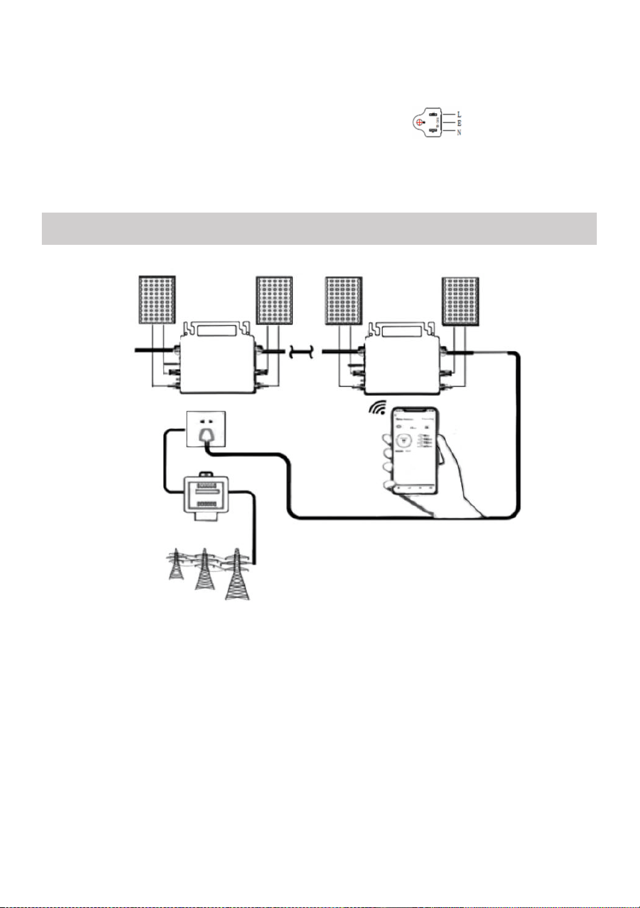
16. Wiederholen Sie die Schritte 1 bis 3, um die Installation des
Mikro-Wechselrichters abzuschließen.
17. Verbinden Sie mehrere Wechselrichter über AC-Ausgangskabel.
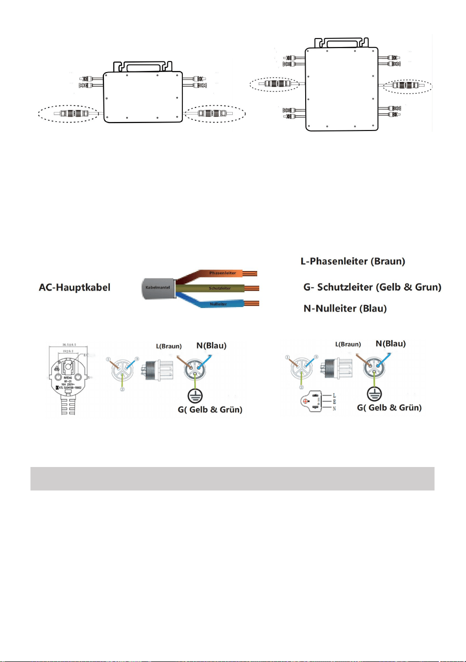
18. Das AC-Hauptkabel wird an das Stromnetz angeschlossen.
Wechselstrom 230 V, 50 Hz, Wechselstrom 110 V, 60 Hz
SCHEMATIC DIAGRAM OF THE COMPLETION OF THE INSTALLATION

- 21 -
GT-600/800
- 22 -
GT-1200
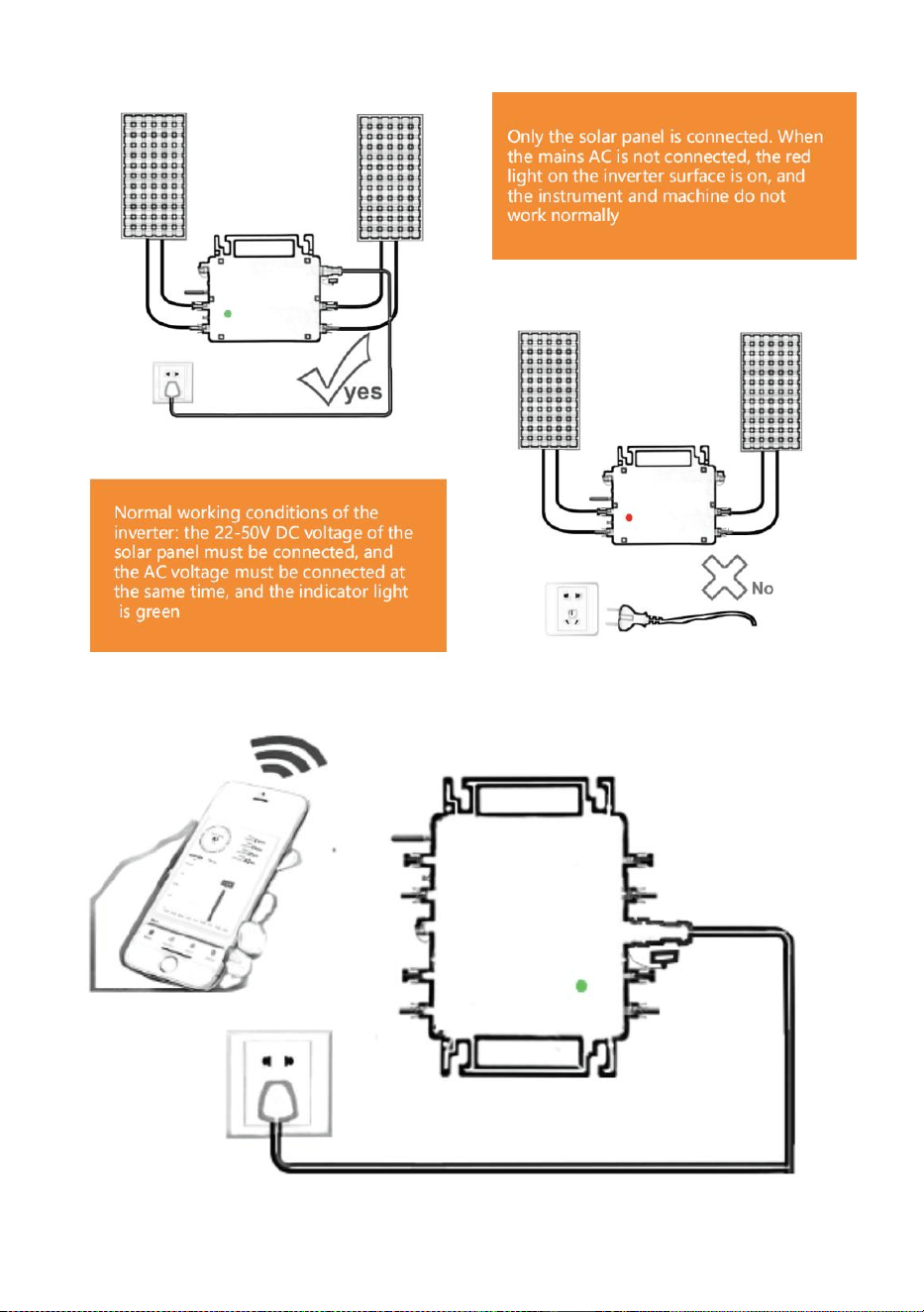
Notiz:

- 23 -
Wenn der Wechselrichter zum ersten Mal gekauft und an das Stromnetz
angeschlossen wird,
Mobiltelefon zur Überwachung, es ist nur notwendig, den Netzwechselstrom
einzuschalten, das blaue Licht daneben blinkt und der Wechselrichter kann
über WLAN oder Bluetooth-Kopplung verbunden werden. Wenn der
Wechselrichter über das Mobiltelefon gesteuert werden kann, wird angezeigt,
dass die Verbindung normal ist.
- 24 -
23. WAS TUN, wenn die Smart-App den Mikro-Wechselrichter nicht finden
kann?
hinzugefügt?
Überprüfen Sie folgende Punkte:
Überprüfen Sie, ob die WiFi-Statusanzeige des Mikro-Wechselrichters „
Blau blinkend“ ist .
Überprüfen Sie, ob die Bluetooth-Funktion Ihres Smart-Geräts
eingeschaltet ist .
Überprüfen Sie, ob das Signal des drahtlosen Netzwerks gut ist.
Wenn all dies der Fall ist und der Wechselrichter immer noch nicht
gefunden wird, drücken Sie die rote Reset-Taste länger als 5 Sekunden, um
zurücksetzen. Nachdem die WLAN-Anzeige wieder blau blinkt, verwenden
Sie die App „Smart Life“, um das Netzwerk neu zu konfigurieren.
24. WAS IST ZU TUN, wenn ich mehrere Mikrowechselrichter konfigurieren
muss?
Installieren Sie alle Mikro-Wechselrichter ordnungsgemäß und sorgen
Sie dafür, dass sie normal funktionieren, um Strom zu erzeugen.
entsprechend der Konfiguration und den Schritten arbeiten. Die App kann
alle Wechselrichter durchsuchen, die auf einmal hinzugefügt werden sollen
und konfigurieren Sie sie auf einmal.
25. WAS TUN, wenn die SSID meines WLAN-Netzwerks oder das Passwort
geändert wird?
Bitte konfigurieren Sie den Wechselrichter entsprechend der
Konfiguration und den Verwendungsschritten neu.
26. WAS TUN, wenn die WiFi-Statusanzeige des Wechselrichters erlischt,
aber die

- 25 -
Gerät angezeigt auf dem App ist nicht online?
Das bedeutet, dass Sie eine Verbindung zum drahtlosen Netzwerkgerät
herstellen können, aber keine Verbindung zur Cloud Server. Das bedeutet,
dass Ihr drahtloses Netzwerkgerät keine Verbindung zum Internet
herstellen kann. Stellen Sie sicher, dass Ihr Das Internet funktioniert
einwandfrei.
27. Der Aufstellungsort des Wechselrichters ist vorübergehend nicht
mit einem Router ausgestattet und es gibt kein WLAN-Signal ?
Wie verbindet die App den Wechselrichter und erkennt, ob der
Wechselrichter ordnungsgemäß funktioniert?
Sie können mit einem inaktiven Smartphone die WLAN-Freigabe des
Mobilfunk-Hotspots öffnen für Verbindung und konfigurieren Sie die
Netzwerkverbindung nach der Installation des Routers neu.
28. Es gibt mehrere WLAN-Signale. Können wir verschiedene
WLAN-Signale verbinden?
Nein, die WLAN-Verbindung des Mikro-Wechselrichters und des
Smartphones muss konsistent sein, bevor das Netzwerk konfiguriert
werden kann.
29. Kann die App den Mikrowechselrichter an verschiedenen Orten
konfigurieren? Kann ich Daten an verschiedenen Orten anzeigen?
Sie können den Mikro-Wechselrichter nicht an verschiedenen Orten
konfigurieren, aber Sie können Daten an verschiedenen Orten anzeigen.
Der Wechselrichter lädt alle 3–5 Minuten die neuesten Statusdaten auf
den Cloud-Server hoch.
30. Nachdem Sie überprüft haben, dass kein Problem vorliegt, kann
die App den Mikro-Wechselrichter immer noch nicht finden.
Um den Wechselrichter zurückzusetzen, halten Sie die rote Taste des
Wechselrichters länger als 5 Sekunden gedrückt.
Nachdem die WLAN-Anzeige erneut blinkt, konfigurieren Sie das

- 26 -
Netzwerk mithilfe der App neu.
31. WAS KANN ICH TUN, wenn ich denselben Wechselrichter auf
zwei oder mehr Smart-Geräten überwachen möchte?
Mit der Funktion „Gerät teilen“ können Sie den Wechselrichter für ein
anderes Telefon freigeben.
32. Werden App-Daten gespeichert?
Ja, App-Daten werden auf einem Cloud-Server gespeichert. Nachdem
das Netzwerk erfolgreich konfiguriert wurde, können Sie die Daten
jederzeit und überall anzeigen.
33. Der Wechselrichter lässt sich nachts nicht mit der App
verbinden?
Da das Solarmodul nachts keinen Strom erzeugt, verfügt der
Mikro-Wechselrichter über keine Stromzufuhr. Er ist also offline und eine
Neukonfiguration des Netzwerks ist nachts nicht möglich.
ACCESSORIES LIST
11.Bedienungsanleitung *1
12.Netzkabel für Netzanschluss *1
13.8 mm Durchmesser, 28 mm lang, Innensechskantschraube +
Unterlegscheibe + Feder
Unterlegscheibe + Mutter *2
14.5 mm Durchmesser, 13 mm lang, Innensechskantschraube + Mutter * 2
(600 W/800 W)
4 mm Durchmesser, 8 mm lange Innensechskantschraube *1 (1200 W)
15.WiFi-Antenne *1
- 27 -
Hersteller: Shanghaimuxinmuyeyouxiangongsi
Adresse: Shuangchenglu 803nong11hao1602A-1609shi, baoshanqu,
Shanghai 200000 CN.
Nach AUS importiert: SIHAO PTY LTD, 1 ROKEVA STREETEASTWOOD
NSW 2122 Australien
Importiert in die USA: Sanven Technology Ltd., Suite 250, 9166 Anaheim
Place, Rancho Cucamonga, CA 91730
REP
EC
E-CrossStu GmbH
Mainzer Landstr.69, 60329 Frankfurt am Main.
REP
UK
YH CONSULTING LIMITED.
C/O YH Consulting Limited Office 147, Centurion House,
London Road, Staines-upon-Thames, Surrey, TW18 4AX


- 29 -
Tecnico Supporto e certificato di garanzia elettronica
www.vevor.com/support
MICROINVERTER
MODELLO: GT-600/GT-800/GT-1200
We continue to be committed to provide you tools with competitive price.
"Save Half", "Half Price" or any other similar expressions used by us only represents an
estimate of savings you might benefit from buying certain tools with us compared to the major
top brands and does not necessarily mean to cover all categories of tools offered by us. You
are kindly reminded to verify carefully when you are placing an order with us if you are
actually saving half in comparison with the top major brands.

- 1 -
MODELLO: GT-600/GT-800/GT-1200
MODELLI GT-600/GT-800/GT-1200
Have product questions? Need technical support? Please feel free to
contact us:
Technical Support and E-Warranty Certificate
www.vevor.com/support
NEED HELP? CONTACT US!
This is the original instruction, please read all manual instructions
carefully before operating. VEVOR reserves a clear interpretation of our
user manual. The appearance of the product shall be subject to the
product you received. Please forgive us that we won't inform you again if
there are any technology or software updates on our product.
MICRO INVERTER

- 2 -
Attenzione: per ridurre il rischio di lesioni, l'utente deve leggere
attentamente il manuale di istruzioni.
Questo prodotto è soggetto alle disposizioni della Direttiva
Europea 2012/19/CE. Il simbolo raffigurante un bidone della
spazzatura barrato indica che il prodotto richiede la raccolta
differenziata dei rifiuti nell'Unione Europea. Ciò si applica al
prodotto e a tutti gli accessori contrassegnati con questo
simbolo. I prodotti contrassegnati come tali non possono essere
smaltiti con i normali rifiuti domestici, ma devono essere portati
in un punto di raccolta per il riciclaggio di dispositivi elettrici ed
elettronici
ATTENZIONE: PERICOLO DI SCOSSE ELETTRICHE
Il prodotto viene utilizzato in combinazione con una fonte di energia
permanente (batteria). Anche se l'apparecchiatura è spenta, un pericolo
tensione elettrica può verificarsi ai terminali di ingresso e/o di uscita.
Spegnere sempre l'alimentazione CA e scollegare la batteria prima
eseguire la manutenzione.
Il prodotto non contiene parti interne riparabili dall'utente. Non rimuovere il
pannello frontale e non mettere in funzione il prodotto se non sono montati
tutti i pannelli. Tutta la manutenzione deve essere eseguita da personale
qualificato.
Non utilizzare mai il prodotto in siti in cui potrebbero verificarsi esplosioni di
gas o polvere. Fare riferimento alle specifiche fornite dal produttore del
batteria per garantire che la batteria sia adatta all'uso con questo prodotto.
Le istruzioni di sicurezza del produttore della batteria devono essere
sempre osservato.
ATTENZIONE: non sollevare oggetti pesanti senza assistenza.
Installazione
Prima di iniziare le attività di installazione, leggere le istruzioni di
installazione.
Questo prodotto è un dispositivo di classe di sicurezza I (fornito con un

- 3 -
terminale di terra per motivi di sicurezza). I suoi terminali di ingresso e/o
uscita CA deve essere dotato di messa a terra ininterrotta per motivi di
sicurezza. Un punto di messa a terra aggiuntivo è situato all'esterno del
prodotto. Se si può presumere che la protezione di messa a terra sia
danneggiata, il prodotto deve essere messo fuori servizio e impedire che
venga rimesso in funzione accidentalmente; contattare personale di
manutenzione qualificato.
Assicurarsi che i cavi di collegamento siano dotati di fusibili e interruttori
automatici. Non sostituire mai un dispositivo di protezione con un
componente di un
tipo diverso. Fare riferimento al manuale per la parte corretta.
Prima di accendere il dispositivo, verificare che la sorgente di tensione
disponibile sia conforme alle impostazioni di configurazione del prodotto.
descritto nel manuale.
Assicurarsi che l'attrezzatura venga utilizzata nelle corrette condizioni
operative. Non utilizzarla mai in un ambiente umido o polveroso.
Assicurarsi che attorno al prodotto vi sia sempre sufficiente spazio libero
per la ventilazione e che le aperture di ventilazione non siano ostruite.
Installare il prodotto in un ambiente resistente al calore. Assicurarsi quindi
che non vi siano sostanze chimiche, parti in plastica, tende o altri tessuti,
ecc.
nelle immediate vicinanze dell'apparecchiatura.
Trasporto e stoccaggio
Durante lo stoccaggio o il trasporto del prodotto, assicurarsi che
l'alimentazione di rete e i cavi della batteria siano scollegati.
Non si assume alcuna responsabilità per eventuali danni durante il
trasporto se l'apparecchiatura non viene trasportata nell'imballaggio
originale.
Conservare il prodotto in un ambiente asciutto; la temperatura di
conservazione deve essere compresa tra -40°C e 65 ° C.
Per informazioni sul trasporto, lo stoccaggio, la carica, la ricarica e lo
smaltimento della batteria, fare riferimento al manuale del produttore della
batteria.
- 4 -
SPECIFICATIONS
Sei benvenuti a scegliere i nostri prodotti inverter solari micro-collegati alla rete .
Dati di specificazione
Modello
La GT-600
La GT-800
La GT-1200
Dati di input (CC, FV)
Numero di connettori MC4 in
ingresso
2 set
4 set
Intervallo di tensione di
funzionamento
DC18V-50V
Corrente massima di ingresso
12A*2
14A*2
16A*2
Dati di uscita (CA)
Tipo di rete monofase
AC230V
AC230V
CA 110 V o CA 230 V
Potenza massima in uscita
600W
800W
1200W
Corrente di uscita nominale
2,6 Un
3,5 A
10,9 A o 5,2 A
Tensione di uscita nominale
AC230V
AC230V
CA 110 V o CA 230 V
Gamma di frequenza di uscita
Frequenza 50 Hz
Frequenza 50
Hz
60 Hz o 50 Hz
Fattore di potenza
≥0,99%
Distorsione armonica totale
Distorsione armonica totale <5%
Unità massime per filiale
@230VAC: 4 unità
@230VAC: 3 unità
@ 110 VAC: 2 unità oppure @
230VAC: 3 unità
Efficienza massima
95%
Efficienza nominale MPPT
99,5%
Consumo energetico notturno
≤1W
Dati meccanici
Intervallo di temperatura
ambiente di funzionamento
da -40℃ a +65℃
Intervallo di temperatura di
stoccaggio
da -40°C a +85°C
Dimensioni (L*A*P)
305 * 186 * 44 millimetri
490 * 254 * 50 millimetri
Grado di impermeabilità
Grado di
protezione IP67
Grado di
protezione
IP65/IP67
(Fare
Grado di protezione
IP67
- 5 -
riferimento alle
informazioni
riportate sulla
targhetta del
prodotto)
Comunicazione
WIFI (monitoraggio cloud)
Funzioni di protezione
Protezione dell'isola isolata, protezione della tensione
Protezione della frequenza
Protezione della temperatura, protezione della corrente, ecc.
INSTALLATION SCHEMATIC
Metodo di assemblaggio parallelo monofase di micro invertitore
La GT-600
10. @Rete monofase 230V Massimo 4 unità 600W Micro inverter per ramo.
11. La potenza massima in ingresso CC di ciascun inverter è di 600 W (la potenza
massima in uscita del modulo fotovoltaico)
la potenza è 2x300W) .
12. Il VOC dei moduli fotovoltaici non deve essere maggiore della tensione
massima di ingresso CC
di Micro inverter .
La GT-800

- 6 -
10. @Rete monofase 230V Massimo 3 unità 8 00W Micro inverter per ramo.
11. La potenza massima in ingresso CC di ciascun inverter è di 800 W (la potenza
massima in uscita del modulo FV)
la potenza è 2x 4 00W) .
12. Il VOC dei moduli fotovoltaici non deve essere maggiore della tensione
massima di ingresso CC
di Micro inverter .

- 7 -
La GT-1200
10. @Rete monofase 110 V Massimo 2 unità o @rete monofase 230V
Massimo 3 unità 12 00W Micro inverter per ramo.
11. La potenza massima in ingresso CC di ciascun inverter è 12 00W (la potenza
massima in uscita del modulo FV)
la potenza è 2x 6 00W) .
12. Il VOC dei moduli fotovoltaici non deve essere maggiore della tensione
massima di ingresso CC
di Micro inverter .
WIRING SCHEMATIC
Metodo di collegamento monofase del microinverter
Modello GT-600/GT-800
La GT-1200

- 8 -
Metodo di collegamento trifase del microinverter
Modello GT-600/GT-800
La GT-1200
- 9 -
19. Precauzioni
Si prega di notare che durante il collegamento del microinverter sussiste
il rischio di scosse elettriche!
Il microinverter si riscalda durante il funzionamento! Proteggiti
di conseguenza dalle ustioni !
Prima di configurare il monitoraggio del cloud WiFi, installare
correttamente il micro inverter e farlo funzionare normalmente .
COME dispositivo mart (smartphone o tablet) con funzione Bluetooth e
sistema Android oppure deve essere disponibile un dispositivo di rete
wireless, ad esempio un router wireless, in grado di fornire servizi WiFi
e Internet .
Per configurare il monitoraggio cloud WLAN, attivare prima la funzione
Bluetooth del dispositivo smart.
Assicurati che il tuo dispositivo smart utilizzi la stessa rete WiFi del
micro inverter da configurare e che possa connettersi ai dispositivi di
rete wireless e accedere a Internet nella stessa posizione del micro
inverter .
Assicurarsi che la distanza tra il dispositivo di rete wireless e il
microinverter non superi i 20 m e che non vi siano ostacoli o che siano
pochi.
20. Descrizione hardware
MICRO INVERTER WIFI CLOUD MONITORING
WIFI
Set/Reset Button
WIFI Status
LED Indicator

- 10 -
21. LED di stato WIFI
La luce blu lampeggia dopo essere sempre accesa = il modulo di
monitoraggio cloud WiFi è in attesa di configurazione.
Luce blu spenta dopo essere rimasta sempre accesa = il modulo di
monitoraggio cloud WiFi si avvia ed entra nel normale stato di
funzionamento.
La luce blu lampeggia = la rete non è configurata o la rete non riesce a
connettersi al dispositivo di rete wireless, oppure il micro inverter è
stato eliminato dal cloud.
Nessuna luce = il monitoraggio del cloud WiFi funziona normalmente .
22. Preparazione prima della configurazione e dell'uso
Installare correttamente il microinverter e farlo funzionare normalmente
per generare energia.
Scarica e installa il O App "Smart Life" cercandola nell'app store
Android o Apple corrispondente.
Attiva la funzione Bluetooth del tuo dispositivo smart .
Controlla che il tuo dispositivo di rete wireless (ad esempio il router
wireless) funzioni correttamente e sia connesso a Internet .
Utilizza il tuo dispositivo intelligente ( O "Vita intelligente" App
installata) nel luogo di installazione del micro inverter per connettersi al
dispositivo di rete wireless. Se riesci ad accedere normalmente a
Internet , segui le istruzioni per la configurazione e l'utilizzo nella pagina
successiva.

- 11 -
23. Fasi di configurazione del monitoraggio cloud WIFI .
- 12 -
24. Utilizzo dell'app di monitoraggio cloud WIFI .
Modifica il nome del dispositivo
Fare clic sul dispositivo da modificare nell'elenco dei dispositivi nella
home page per accedere alla pagina dei dettagli delle informazioni sul
dispositivo (Figura 5).
- 13 -
Fare clic sul pulsante in alto a destra per accedere alla pagina di
impostazione del dispositivo (Figura 6), continuare a fare clic sul
pulsante in alto nella pagina del nome e della posizione (Figura 7)
cliccare sulla voce nome, quindi immettere un nuovo nome e salvarlo
(Figura 8).

- 14 -
Rimuovi dispositivo
Fare clic sul dispositivo da eliminare nell'elenco dei dispositivi nella
home page per immettere le informazioni sul dispositivo pagina dei
dettagli (Figura 5).
Fare clic sul pulsante in alto a destra per accedere alla pagina di
impostazione del dispositivo (Figura 6). Fare clic sul pulsante "Rimuovi
dispositivo" in basso (Figura 9), fare clic sul pulsante "Disconnetti" per
rimuovere il dispositivo o fare clic sul pulsante "Disconnetti e cancella
dati" per rimuovere il dispositivo e cancellare contemporaneamente
tutti i dati salvati dal dispositivo nel cloud.

- 15 -
Condividi il dispositivo con altri
Fare clic sul dispositivo da condividere nell'elenco dei dispositivi nella
home page per accedere alla pagina dei dettagli delle informazioni sul
dispositivo (Figura 5).
Clicca sul pulsante in alto a destra per entrare nel pagina di
impostazione del dispositivo (Figura 6).
Fare clic sulla voce "Condividi dispositivo" per accedere al dispositivo
pagina di condivisione (Figura 10) , fare clic pulsante per
accedere alla pagina " Aggiungi condivisione " (Figura 11) e seleziona il
modo migliore di condivisione che ritieni più opportuno comodo
condividere il link del micro inverter.

- 16 -
19. Il processo di installazione del fissaggio dell'inverter alla staffa FV con
montaggio
le viti sono le seguenti:
Modello GT-600/800 La GT-1200
20. Collegare la CC del fotovoltaico all'inverter e prestare attenzione a
distinguere
tra positivo e negativo, come mostrato di seguito:
Modelli GT-600/800/1200
21. Aprire il coperchio impermeabile sul lato di uscita CA del micro inverter,
e poi collegarlo alla corrente alternata. Come segue:
INSTRUCTIONS FOR INSTALLATION WIRING
- 17 -
Modelli GT-600/800/1200
22. Ripetere i passaggi da 1 a 3 per completare l'installazione del
microinverter.
23. Collegare più inverter tramite cavi di uscita CA.
24. Il cavo principale CA è collegato alla rete elettrica.
AC230V 50Hz AC110V 60Hz
SCHEMATIC DIAGRAM OF THE COMPLETION OF THE INSTALLATION
- 18 -
GT-600/800

- 19 -
La GT-1200
Nota:

- 20 -
Quando l'inverter viene acquistato per la prima volta e collegato all'
telefono cellulare per il monitoraggio, è necessario solo accendere la rete
elettrica CA, la luce blu accanto lampeggia e l'inverter può essere collegato
tramite WIFI o associazione Bluetooth. Quando l'inverter può essere
controllato tramite il telefono cellulare, è indicato che la connessione è
normale.

- 21 -
34. COSA FARE quando la Smart-App non riesce a trovare il micro inverter
aggiunto?
Controllare i seguenti punti:
Controllare se l'indicatore di stato WiFi del micro inverter è nello stato
"Blu lampeggiante" .
Controlla se la funzione Bluetooth del tuo dispositivo smart è attivata .
Controllare se il segnale della rete wireless è buono.
Se tutto questo è il caso e l'inverter non viene ancora trovato, premere il
pulsante rosso di reset per più di 5 secondi per reset. Dopo che la spia WiFi
lampeggia di nuovo in blu, usa l'app "Smart Life" per riconfigurare la rete.
35. COSA FARE se devo configurare più microinverter?
Installare correttamente tutti i microinverter e farli funzionare
normalmente per generare energia, quindi operare secondo la
configurazione e utilizzando i passaggi. L'App può cercare tutti gli inverter
da aggiungere in una volta tempo e configurarli in una sola volta.
36. COSA FARE se l'SSID della mia rete WiFi o la password vengono
modificati?
Riconfigurare l'inverter seguendo la configurazione e i passaggi indicati.
37. COSA FARE se l'indicatore di stato WiFi dell'inverter si spegne, ma il
dispositivo visualizzato sul l'app non è online?
Ciò significa che puoi connetterti al dispositivo di rete wireless, ma non
puoi connetterti al cloud server. Significa che il tuo dispositivo di rete
wireless non riesce a connettersi a Internet. Assicurati che il tuo Internet
funziona correttamente.
38. Il sito di installazione dell'inverter è temporaneamente sprovvisto
di router e di segnale WiFi ?
In che modo l'app collega l'inverter e rileva se funziona correttamente?
È possibile utilizzare uno smartphone inattivo per aprire la condivisione

- 22 -
WiFi dell'hotspot del segnale del telefono cellulare per connessione e
riconfigurare la connessione di rete dopo aver installato il router.
39. Ci sono diversi segnali WiFi in giro. Possiamo collegare diversi
segnali WiFi?
No, la connessione WiFi del microinverter e dello smartphone deve
essere coerente prima che la rete possa essere configurata.
40. L'app può configurare il micro inverter in luoghi diversi? Posso
visualizzare i dati in luoghi diversi?
Non è possibile configurare il micro inverter in luoghi diversi, ma è
possibile visualizzare i dati in luoghi diversi. L'inverter carica i dati di stato
più recenti sul server cloud ogni 3-5 minuti.
41. Dopo aver verificato che non ci siano problemi, l'app non riesce
ancora a trovare il microinverter.
Per resettare l'inverter, tenere premuto il pulsante rosso dell'inverter
per più di 5 secondi.
Dopo che l'indicatore WiFi lampeggia di nuovo, utilizzare l'app per
riconfigurare la rete.
42. COSA FARE se voglio monitorare lo stesso inverter su due o più
dispositivi smart?
È possibile condividere l'inverter con un altro telefono utilizzando la
funzione di condivisione del dispositivo.
43. I dati dell'app verranno salvati?
Sì, i dati dell'app saranno archiviati sul server cloud. Dopo che la rete è
stata configurata correttamente, puoi visualizzare i dati in qualsiasi
momento e luogo.
44. L'inverter non può essere collegato all'app durante la notte?
Di notte, poiché il pannello solare non genera energia, il microinverter
non ha alcun ingresso di potenza, quindi sarà offline e sarà impossibile

- 23 -
riconfigurare la rete durante la notte.
ACCESSORIES LIST
16.Istruzioni per l'uso *1
17.Cavo di alimentazione collegato alla rete *1
18.Vite a testa esagonale da 8 mm di diametro e 28 mm di lunghezza +
rondella piatta + molla
rondella+dado *2
19.Vite a esagono incassato da 5 mm di diametro, 13 mm di lunghezza +
dado *2 (600 W/800 W)
Vite a brugola esagonale da 4 mm di diametro e 8 mm di lunghezza *1
(1200 W)
20.Antenna WiFi *1

- 24 -
Produttore: Shanghaimuxinmuyeyouxiangongsi
Indirizzo: Shuangchenglu 803nong11hao1602A-1609shi, baoshanqu,
shanghai 200000 CN.
Importato in AUS: SIHAO PTY LTD, 1 ROKEVA STREETEASTWOOD
NSW 2122 Australia
Importato negli USA: Sanven Technology Ltd., Suite 250, 9166 Anaheim
Place, Rancho Cucamonga, CA 91730
REP
EC
E-CrossStu GmbH
Mainzer Landstr.69, 60329 Frankfurt am Main.
REP
UK
YH CONSULTING LIMITED.
C/O YH Consulting Limited Office 147, Centurion House,
London Road, Staines-upon-Thames, Surrey, TW18 4AX


- 26 -
Técnico Certificado de soporte y garantía electrónica
www.vevor.com/support
MICRO INVERSOR
MODELO: GT-600/GT-800/GT-1200
We continue to be committed to provide you tools with competitive price.
"Save Half", "Half Price" or any other similar expressions used by us only represents an
estimate of savings you might benefit from buying certain tools with us compared to the major
top brands and does not necessarily mean to cover all categories of tools offered by us. You
are kindly reminded to verify carefully when you are placing an order with us if you are
actually saving half in comparison with the top major brands.
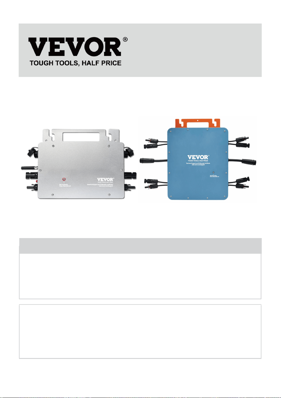
- 1 -
MODELO: GT-600/GT-800/GT-1200
GT-600/GT-800 GT-1200
Have product questions? Need technical support? Please feel free to
contact us:
Technical Support and E-Warranty Certificate
www.vevor.com/support
NEED HELP? CONTACT US!
This is the original instruction, please read all manual instructions
carefully before operating. VEVOR reserves a clear interpretation of our
user manual. The appearance of the product shall be subject to the
product you received. Please forgive us that we won't inform you again if
there are any technology or software updates on our product.
MICRO INVERTER

- 2 -
Advertencia: Para reducir el riesgo de lesiones, el usuario debe
leer atentamente el manual de instrucciones.
Este producto está sujeto a las disposiciones de la Directiva
Europea 2012/19/CE. El símbolo que muestra un contenedor
de basura tachado indica que el producto requiere una
recogida selectiva de residuos en la Unión Europea. Esto se
aplica al producto y a todos los accesorios marcados con este
símbolo. Los productos marcados como tales no pueden
desecharse con los residuos domésticos normales, sino que
deben llevarse a un punto de recogida para reciclar dispositivos
eléctricos y electrónicos.
ADVERTENCIA: PELIGRO DE DESCARGA ELÉCTRICA
El producto se utiliza en combinación con una fuente de energía
permanente (batería). Incluso si el equipo está apagado, puede producirse
un peligro
Puede haber voltaje eléctrico en los terminales de entrada y/o salida.
Siempre apague la alimentación de CA y desconecte la batería antes de
realizando mantenimiento.
El producto no contiene piezas internas que puedan ser reparadas por el
usuario. No retire el panel frontal ni ponga el producto en funcionamiento a
menos que todos los paneles estén instalados. Todo el mantenimiento
debe ser realizado por personal calificado.
Nunca utilice el producto en lugares donde puedan producirse explosiones
de gas o polvo. Consulte las especificaciones proporcionadas por el
fabricante del producto. batería para asegurarse de que la batería sea
adecuada para su uso con este producto. Las instrucciones de seguridad
del fabricante de la batería siempre deben estar disponibles. observado.
ADVERTENCIA: no levante objetos pesados sin ayuda.
Instalación
Lea las instrucciones de instalación antes de comenzar las actividades de
instalación.

- 3 -
Este producto es un dispositivo de seguridad de clase I (se suministra con
un terminal de tierra por motivos de seguridad). Sus terminales de entrada
y/o salida de CA Por razones de seguridad, debe contar con una conexión
a tierra ininterrumpida. Hay un punto de conexión a tierra adicional en el
exterior. del producto. Si se puede suponer que la protección de puesta a
tierra está dañada, se debe dejar de utilizar el producto y evitar que se
vuelva a poner en funcionamiento accidentalmente; póngase en contacto
con personal de mantenimiento cualificado.
Asegúrese de que los cables de conexión estén provistos de fusibles y
disyuntores. Nunca sustituya un dispositivo de protección por un
componente de un
Tipo diferente. Consulte el manual para conocer la pieza correcta.
Compruebe antes de encender el dispositivo si la fuente de voltaje
disponible se ajusta a los ajustes de configuración del producto. descrito
en el manual.
Asegúrese de que el equipo se utilice en las condiciones de
funcionamiento adecuadas. Nunca lo utilice en un entorno húmedo o
polvoriento.
Asegúrese de que siempre haya suficiente espacio libre alrededor del
producto para su ventilación y que las aberturas de ventilación no estén
bloqueadas.
Instale el producto en un entorno resistente al calor. Asegúrese de que no
haya productos químicos, piezas de plástico, cortinas u otros tejidos, etc.
en las inmediaciones del equipo.
Transporte y almacenamiento
Al almacenar o transportar el producto, asegúrese de que los cables de
alimentación de red y de la batería estén desconectados.
No se aceptará ninguna responsabilidad por daños durante el transporte si
el equipo no se transporta en su embalaje original.
Conservar el producto en un ambiente seco; la temperatura de
almacenamiento debe oscilar entre –40°C y 65 ° C.
Consulte el manual del fabricante de la batería para obtener información
sobre el transporte, almacenamiento, carga, recarga y eliminación de la

- 4 -
batería.
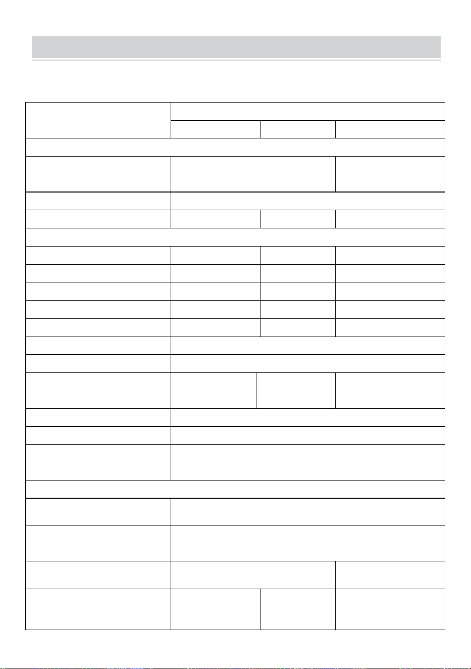
- 5 -
SPECIFICATIONS
Eres Bienvenido a elegir nuestros productos de micro inversores solares
conectados a la red .
Datos de especificación
Modelo
GT-600
GT-800
GT-1200
Datos de entrada (CC, PV)
Número de conector MC4 de
entrada
2 juegos
4 juegos
Rango de voltaje de operación
CC 18 V-50 V
Corriente máxima de entrada
12A*2
14A*2
16A*2
Datos de salida (CA)
Tipo de red monofásica
CA 230 V
CA 230 V
CA 110 V o CA 230 V
Potencia máxima de salida
600 W
800 W
1200 W
Corriente de salida nominal
2,6 A
3,5 A
10,9 A o 5,2 A
Voltaje de salida nominal
CA 230 V
CA 230 V
CA 110 V o CA 230 V
Rango de frecuencia de salida
50 Hz
50 Hz
60 Hz o 50 Hz
Factor de potencia
≥0,99%
Distorsión armónica total
Distorsión armónica total <5 %
Unidades máximas por sucursal
@230VAC: 4
unidades
@230VAC: 3
unidades
@ 110 V CA: 2 unidades o @ 230 V
CA: 3 unidades
Máxima eficiencia
95%
Eficiencia nominal MPPT
99,5%
Consumo de energía durante la
noche
≤1 W
Datos mecánicos
Rango de temperatura ambiente
de funcionamiento
-40℃ a +65℃
Rango de temperatura de
almacenamiento
-40°C a +85°C
Dimensiones (An. x Al. x Pr.)
305 * 186 * 44 milímetros
490 * 254 * 50
milímetros
Grado de impermeabilidad
IP67
IP65/IP67
(Consulte la
información de
IP67
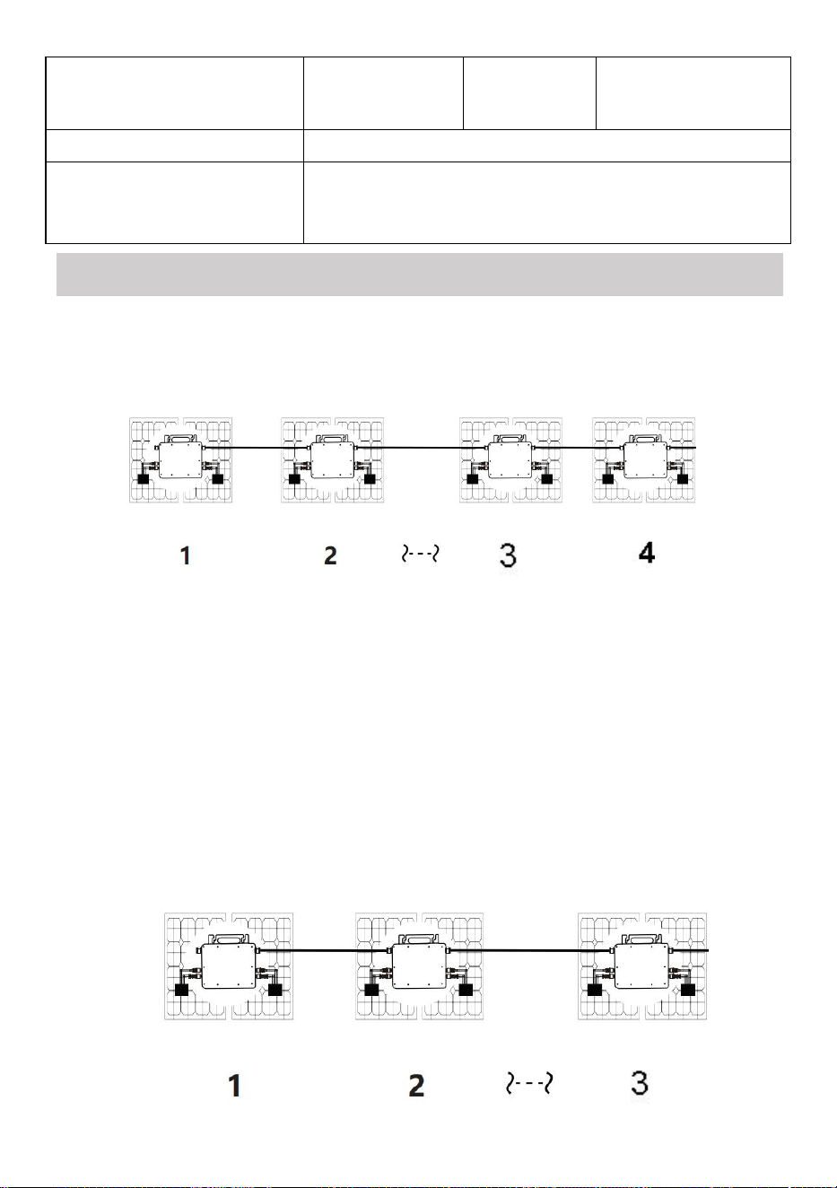
- 6 -
la placa de
identificación
del producto)
Comunicación
WIFI (monitoreo en la nube)
Funciones de protección
Protección de isla aislada, protección de voltaje
Protección de frecuencia
Protección de temperatura, protección de corriente, etc.
INSTALLATION SCHEMATIC
Método de montaje en paralelo monofásico de micro inversor
GT-600
13. @Red monofásica de 230 V Máximo 4 unidades Micro 600W inversores por
rama.
14. La potencia máxima de entrada de CC de cada inversor es de 600 W (la
potencia máxima de salida del módulo fotovoltaico)
La potencia es de 2x300W) .
15. El VOC de los módulos fotovoltaicos no debe ser mayor que el voltaje de
entrada de CC máximo
de Micro inversores .
GT-800

- 7 -
13. @Red monofásica de 230 V Máximo 3 unidades Micro 8 00W inversores por
rama.
14. La potencia máxima de entrada de CC de cada inversor es de 800 W (la
potencia máxima de salida del módulo fotovoltaico)
La potencia es de 2x 4 00W) .
15. El VOC de los módulos fotovoltaicos no debe ser mayor que el voltaje de
entrada de CC máximo
de Micro inversores .

- 8 -
GT-1200
13. monofásica de 110 V Máximo 2 unidades o @red monofásica de 230 V
Máximo 3 unidades Micro 12 00W inversores por rama.
14. La potencia máxima de entrada de CC de cada inversor es de 12,00 W (la
potencia máxima de salida del módulo fotovoltaico)
La potencia es de 2x 6 00W) .
15. El VOC de los módulos fotovoltaicos no debe ser mayor que el voltaje de
entrada de CC máximo
de Micro inversores .
WIRING SCHEMATIC
Método de conexión monofásica del microinversor
GT-600/GT-800
GT-1200

- 9 -
Método de conexión trifásica del microinversor
GT-600/GT-800
GT-1200

- 10 -
25. Precauciones
¡Tenga en cuenta que existe riesgo de descarga eléctrica al conectar el
microinversor!
¡El microinversor se calienta durante el funcionamiento! Protéjase
¡Por consiguiente, de las quemaduras !
Antes de configurar la monitorización de la nube WiFi, instale
correctamente el microinversor y hacer que funcione normalmente .
Como Dispositivo móvil (teléfono inteligente o tableta) con función
Bluetooth y sistema Android o similar y debe estar disponible un
dispositivo de red inalámbrica, por ejemplo, un enrutador inalámbrico
que pueda proporcionar servicio de WiFi e Internet .
Para configurar el monitoreo de la nube WLAN, primero active la función
Bluetooth del dispositivo inteligente.
Asegúrese de que su dispositivo inteligente utilice la misma red WiFi
que el microinversor que se va a configurar y que pueda conectarse a
dispositivos de red inalámbrica y acceder a Internet en la misma
ubicación del microinversor .
Asegúrese de que la distancia entre el dispositivo de red inalámbrica y el
microinversor no supere los 20 m y que no haya obstáculos o que estos
sean pocos.
26. Descripción del hardware
MICRO INVERTER WIFI CLOUD MONITORING
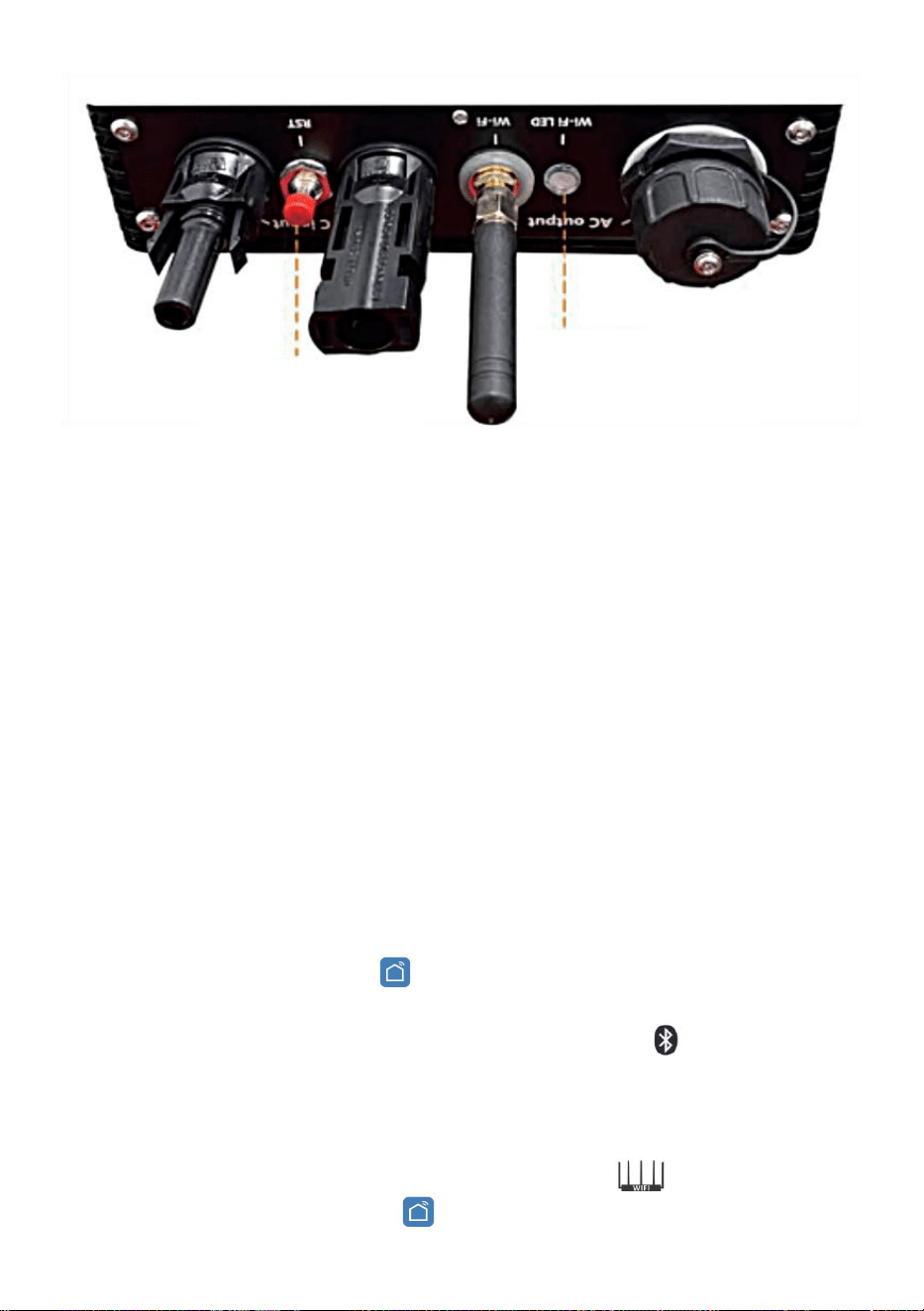
- 11 -
27. LED de estado de WIFI
La luz azul parpadea después de estar siempre encendida = el módulo
de monitoreo en la nube WiFi está esperando la configuración.
La luz azul se apaga después de estar siempre encendida = el módulo de
monitoreo en la nube WiFi se inicia y entra en el estado de
funcionamiento normal.
La luz azul parpadea = la red no está configurada o la red no puede
conectarse al dispositivo de red inalámbrica, o el microinversor se ha
eliminado de la nube.
Sin luz = el monitoreo en la nube WiFi está funcionando normalmente .
28. Preparación antes de la configuración y el uso
Instale correctamente el microinversor y haga que funcione
normalmente para generar energía.
Descargue e instale el o Aplicación “Smart Life” buscándola en la
tienda de aplicaciones de Android o Apple correspondiente.
Active la función Bluetooth de su dispositivo inteligente .
Verifique que su dispositivo de red inalámbrica (como un enrutador
inalámbrico) esté funcionando correctamente y esté conectado a
Internet .
Utilice su dispositivo inteligente ( o "Vida inteligente" Aplicación
WIFI
Set/Reset Button
WIFI Status
LED Indicator
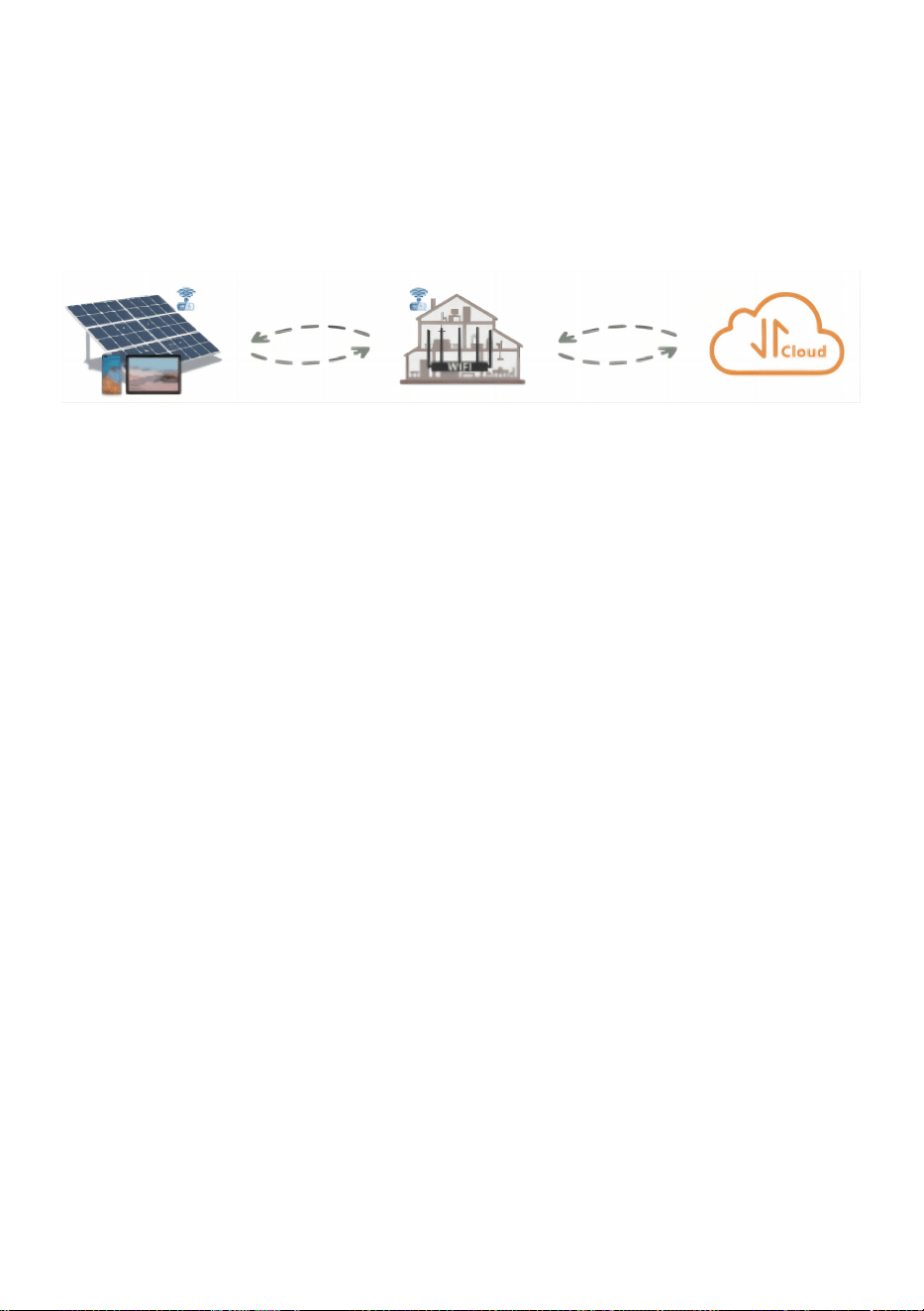
- 12 -
instalada) en la ubicación de instalación del microinversor para
conectarlo al dispositivo de red inalámbrica. Si puede acceder a Internet
normalmente , siga las instrucciones de configuración y uso en la
página siguiente.

- 13 -
29. Pasos de configuración de la monitorización de la nube WIFI .

- 14 -
30. Uso de la aplicación de monitoreo en la nube WIFI .
Modificar el nombre del dispositivo
Haga clic en el dispositivo que desea modificar en la lista de dispositivos
en la página de inicio para ingresar a la página de detalles de
información del dispositivo (Figura 5).

- 15 -
Haga clic en el botón en la parte superior derecha para ingresar a la
página de configuración del dispositivo (Figura 6), Continúe haciendo
clic en el botón superior En la página de nombre y posición (Figura
7), haga clic en el elemento de nombre, luego ingrese un nuevo nombre
y guárdelo (Figura 8).

- 16 -
Quitar dispositivo
Haga clic en el dispositivo que desea eliminar en la lista de dispositivos
en la página de inicio para ingresar la información del dispositivo
página de detalles (Figura 5).
Haga clic en el botón en la parte superior derecha para ingresar a la
página de configuración del dispositivo (Figura 6). Haga clic en el botón
"Eliminar dispositivo" a continuación (Figura 9), haga clic en el botón
"Desconectar" para Retire el dispositivo o haga clic en el botón
"Desconectar y borrar datos" para eliminar el dispositivo y borrar todos
los datos guardados por el dispositivo en la nube al mismo tiempo.

- 17 -
Compartir dispositivo con otros
Haga clic en el dispositivo que desea compartir en la lista de
dispositivos en la página de inicio para ingresar a la página de detalles
de información del dispositivo (Figura 5).
Haga clic en el botón de la parte superior derecha para ingresar al
Página de configuración del dispositivo (Figura 6).
Haga clic en el elemento "Compartir dispositivo" para ingresar al
dispositivo. página para compartir (Figura 10) , haga clic
botón para ingresar a la página “ Agregar uso compartido ” (Figura 11),
y Seleccione la mejor forma de compartir que crea que es más
conveniente. Es conveniente compartir el enlace del micro inversor.
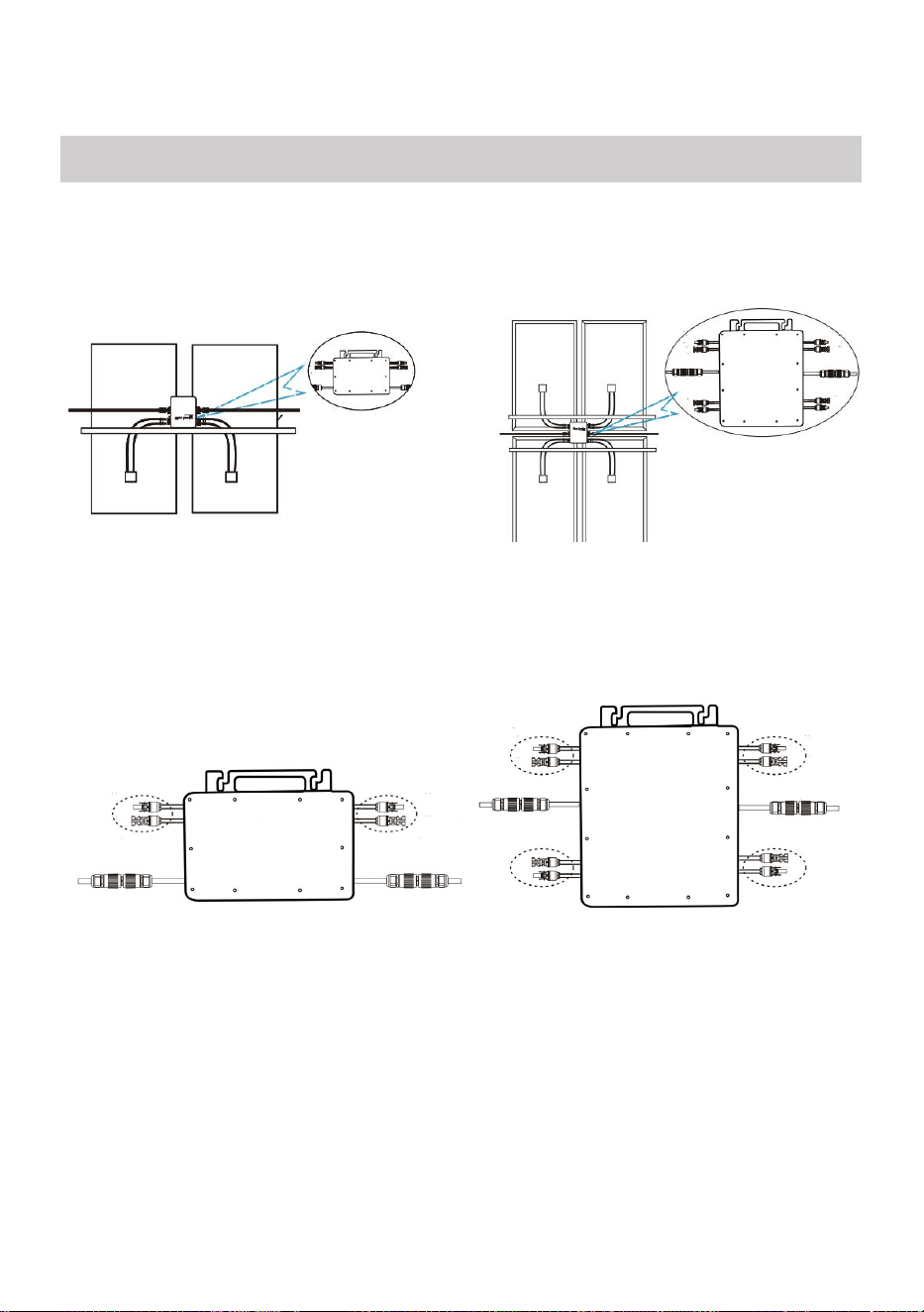
- 18 -
25. El proceso de instalación de fijación del inversor al soporte fotovoltaico
con montaje
Los tornillos son los siguientes:
GT-600/800 GT-1200
26. Conecte la CC del PV al inversor y preste atención a distinguir
entre positivo y negativo, como se muestra a continuación:
GT-600/800 GT-1200
27. Abra la cubierta impermeable en el lado de salida de CA del
microinversor,
y luego conéctelo a la corriente alterna. De la siguiente manera:
INSTRUCTIONS FOR INSTALLATION WIRING
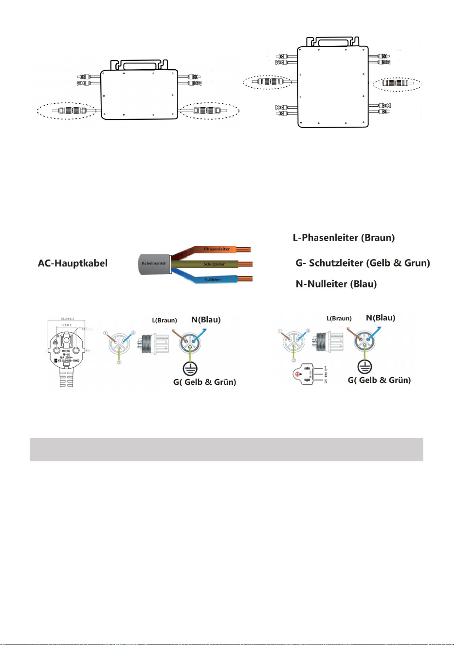
- 19 -
GT-600/800 GT-1200
28. Repita los pasos 1 a 3 para completar la instalación del microinversor.
29. Conecte varios inversores a través de cables de salida de CA.
30. El cable principal de CA está conectado a la red eléctrica.
CA 230 V 50 Hz CA 110 V 60 Hz
SCHEMATIC DIAGRAM OF THE COMPLETION OF THE INSTALLATION

- 20 -
GT-600/800

- 21 -
GT-1200
Nota:

- 22 -
Cuando se compra el inversor por primera vez y se conecta a la
Para controlar el inversor a través del teléfono móvil, basta con encender la
red eléctrica, la luz azul que se encuentra al lado parpadea y se puede
conectar el inversor a través de Wi-Fi o emparejamiento por Bluetooth.
Cuando se puede controlar el inversor a través del teléfono móvil, se indica
que la conexión es normal.

- 23 -
45. QUÉ HACER cuando la Smart-App no encuentra el micro inversor que se
va a conectar
¿agregado?
Compruebe los siguientes puntos:
Verifique si el indicador de estado WiFi del microinversor está en el
estado "parpadeando en azul" .
Compruebe si la función Bluetooth de su dispositivo inteligente está
activada .
Compruebe si la señal de la red inalámbrica es buena.
Si todo esto sucede y aún no se encuentra el inversor, presione el botón
rojo de reinicio durante más de 5 segundos para Restablecer. Después de
que la luz indicadora de WiFi parpadee en azul nuevamente, use la
aplicación "Smart Life" para reconfigurar la red.
46. ¿QUÉ HACER si tengo varios micro inversores para configurar?
Instale todos los micro inversores correctamente y haga que funcionen
normalmente para generar energía y luego Operar según la configuración
y los pasos de uso. La aplicación puede buscar todos los inversores que
se agregarán a la vez. tiempo y configurarlos a la vez.
47. ¿QUÉ HACER si cambia el SSID de mi red WiFi o la contraseña?
Reconfigure el inversor de acuerdo con la configuración y los pasos de
uso.
48. QUÉ HACER si el indicador de estado WiFi del inversor se apaga, pero el
dispositivo que se muestra en la ¿La aplicación no está en línea?
Esto significa que puedes conectarte al dispositivo de red inalámbrica,
pero no puedes conectarte a la nube. servidor. Significa que su dispositivo

- 24 -
de red inalámbrica no puede conectarse a Internet. Asegúrese de que su
Internet está funcionando correctamente.
49. ¿ El lugar de instalación del inversor temporalmente no está
equipado con un enrutador y no hay señal WiFi ?
¿ Cómo conecta la aplicación al inversor y detecta si éste funciona
correctamente?
Puede utilizar un teléfono inteligente inactivo para abrir el punto de
acceso de señal de teléfono móvil para compartir WiFi. conexión y
reconfigure la conexión de red después de instalar el enrutador.
50. Hay varias señales WiFi alrededor. ¿ Podemos conectar
diferentes señales WiFi?
No, la conexión WiFi del microinversor y del teléfono inteligente deben
ser compatibles antes de poder configurar la red.
51. ¿ La aplicación puede configurar el microinversor en diferentes
lugares? ¿Puedo ver datos en diferentes lugares?
No puede configurar el microinversor en diferentes lugares, pero puede
ver datos en diferentes lugares. El inversor carga los últimos datos de
estado al servidor en la nube cada 3 a 5 minutos.
52. Después de comprobar que no hay ningún problema, la
aplicación sigue sin encontrar el microinversor.
Mantenga presionado el botón rojo del inversor durante más de 5
segundos para reiniciarlo.
Después de que el indicador WiFi vuelva a parpadear, use la
aplicación para reconfigurar la red.

- 25 -
53. ¿QUÉ HACER si quiero monitorizar el mismo inversor en dos o
más dispositivos inteligentes?
Puede compartir el inversor con otro teléfono utilizando la función de
compartir dispositivo.
54. ¿Se guardarán los datos de la aplicación?
Sí, los datos de la aplicación se almacenarán en un servidor en la nube.
Una vez que la red esté configurada correctamente, podrá ver los datos en
cualquier momento y lugar.
55. ¿El inversor no se puede conectar a la aplicación por la noche?
Por la noche, debido a que el panel solar no genera energía, el
microinversor no tiene ninguna entrada de energía, por lo que estará fuera
de línea y será imposible reconfigurar la red por la noche.
ACCESSORIES LIST
21.Instrucciones de funcionamiento *1
22.Cable de alimentación conectado a la red eléctrica *1
23.Tornillo con cabeza hexagonal de 8 mm de diámetro y 28 mm de largo
+ arandela plana + resorte
arandela+tuerca *2
24.Tornillo con cabeza hexagonal de 5 mm de diámetro y 13 mm de largo
+ tuerca *2 (600 W/800 W)
Tornillo de cabeza hexagonal de 4 mm de diámetro y 8 mm de largo *1
(1200 W)
25.Antena WiFi *1

- 26 -
Fabricante: Shanghaimuxinmuyeyouxiangongsi
Dirección: Shuangchenglu 803nong11hao1602A-1609shi, baoshanqu,
shanghai 200000 CN.
Importado a AUS: SIHAO PTY LTD, 1 ROKEVA STREETEASTWOOD
NSW 2122 Australia
Importado a EE. UU.: Sanven Technology Ltd., Suite 250, 9166 Anaheim
Place, Rancho Cucamonga, CA 91730
REP
EC
E-CrossStu GmbH
Mainzer Landstr.69, 60329 Frankfurt am Main.
REP
UK
YH CONSULTING LIMITED.
C/O YH Consulting Limited Office 147, Centurion House,
London Road, Staines-upon-Thames, Surrey, TW18 4AX


- 28 -
Techniczny Wsparcie i certyfikat e-gwarancji
www.vevor.com/support
MIKROINWERTER
MODELE: GT-600/GT-800/GT-1200
We continue to be committed to provide you tools with competitive price.
"Save Half", "Half Price" or any other similar expressions used by us only represents an
estimate of savings you might benefit from buying certain tools with us compared to the major
top brands and does not necessarily mean to cover all categories of tools offered by us. You
are kindly reminded to verify carefully when you are placing an order with us if you are
actually saving half in comparison with the top major brands.

- 1 -
MODELE: GT-600/GT-800/GT-1200
NAZWA UŻYTKOWNIKA: GT-600/GT-800
Have product questions? Need technical support? Please feel free to
contact us:
Technical Support and E-Warranty Certificate
www.vevor.com/support
NEED HELP? CONTACT US!
This is the original instruction, please read all manual instructions
carefully before operating. VEVOR reserves a clear interpretation of our
user manual. The appearance of the product shall be subject to the
product you received. Please forgive us that we won't inform you again if
there are any technology or software updates on our product.
MICRO INVERTER
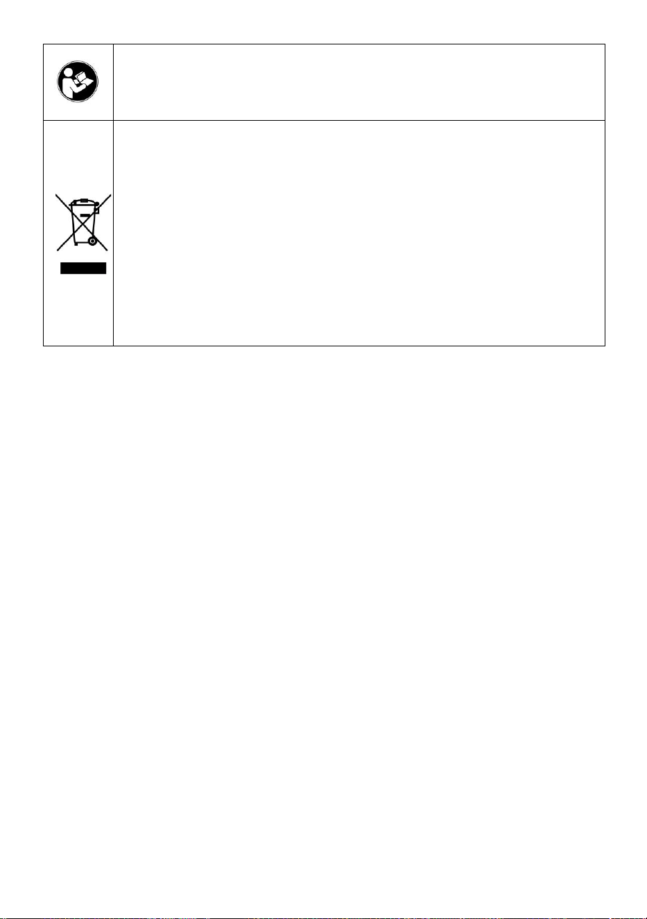
- 2 -
Ostrzeżenie: Aby zminimalizować ryzyko obrażeń, użytkownik
powinien uważnie przeczytać instrukcję obsługi.
Ten produkt podlega postanowieniom Dyrektywy Europejskiej
2012/19/WE. Symbol przedstawiający przekreślony kosz na
śmieci na kółkach oznacza, że produkt wymaga oddzielnej
zbiórki odpadów w Unii Europejskiej. Dotyczy to produktu i
wszystkich akcesoriów oznaczonych tym symbolem.
Produktów oznaczonych w ten sposób nie można wyrzucać
razem ze zwykłymi odpadami domowymi, ale należy je oddać
do punktu zbiórki w celu recyklingu urządzeń elektrycznych i
elektronicznych.
OSTRZEŻENIE: NIEBEZPIECZEŃSTWO PORAŻENIA PRĄDEM
ELEKTRYCZNYM
Produkt jest używany w połączeniu ze stałym źródłem energii (baterią).
Nawet jeśli urządzenie jest wyłączone, istnieje niebezpieczeństwo
napięcie elektryczne może wystąpić na zaciskach wejściowych i/lub
wyjściowych. Zawsze wyłączaj zasilanie prądem zmiennym i odłączaj
akumulator przed
wykonywanie prac konserwacyjnych.
Produkt nie zawiera żadnych wewnętrznych części, które mogą być
serwisowane przez użytkownika. Nie zdejmuj przedniego panelu i nie
uruchamiaj produktu, jeśli nie są zamontowane wszystkie panele. Wszelkie
prace konserwacyjne powinny być wykonywane przez wykwalifikowany
personel.
Nigdy nie używaj produktu w miejscach, w których może dojść do wybuchu
gazu lub pyłu. Zapoznaj się ze specyfikacjami podanymi przez producenta
produktu. baterii, aby upewnić się, że bateria nadaje się do użytku z tym
produktem. Instrukcje bezpieczeństwa producenta baterii powinny być
zawsze zauważony.
OSTRZEŻENIE: nie podnoś ciężkich przedmiotów bez pomocy.
Instalacja

- 3 -
Przed rozpoczęciem czynności instalacyjnych należy zapoznać się z
instrukcją instalacji.
Ten produkt jest urządzeniem klasy bezpieczeństwa I (dostarczanym z
zaciskiem uziemiającym w celach bezpieczeństwa). Jego zaciski
wejściowe i/lub wyjściowe AC musi być wyposażony w nieprzerwane
uziemienie ze względów bezpieczeństwa. Dodatkowy punkt uziemienia
znajduje się na zewnątrz produktu. Jeżeli można przypuszczać, że
zabezpieczenie uziemiające jest uszkodzone, produkt należy wycofać z
eksploatacji i zapobiec przypadkowemu uruchomieniu; należy
skontaktować się z wykwalifikowanym personelem zajmującym się
konserwacją.
Upewnij się, że kable połączeniowe są wyposażone w bezpieczniki i
wyłączniki. Nigdy nie zastępuj urządzenia ochronnego elementem
inny typ. Zapoznaj się z instrukcją, aby znaleźć właściwą część.
Przed włączeniem urządzenia należy sprawdzić, czy dostępne źródło
napięcia jest zgodne z ustawieniami konfiguracji produktu, jak pokazano
na rysunku. Opisano w instrukcji.
Upewnij się, że sprzęt jest używany w odpowiednich warunkach pracy.
Nigdy nie używaj go w wilgotnym lub zakurzonym środowisku.
Należy upewnić się, że wokół produktu zawsze jest wystarczająco dużo
wolnej przestrzeni, aby umożliwić wentylację, a otwory wentylacyjne nie są
zablokowane.
Zainstaluj produkt w środowisku odpornym na ciepło. Upewnij się, że nie
ma żadnych chemikaliów, części z tworzyw sztucznych, zasłon lub innych
tekstyliów itp.
w bezpośrednim sąsiedztwie sprzętu.
Transport i magazynowanie
Podczas przechowywania lub transportu produktu należy upewnić się, że
zasilanie sieciowe i przewody akumulatora są odłączone.
Nie ponosimy odpowiedzialności za uszkodzenia powstałe w transporcie,
jeżeli sprzęt nie był przewożony w oryginalnym opakowaniu.
Przechowywać w suchym miejscu, w temperaturze od –40°C do 65 ° C.
Informacje dotyczące transportu, przechowywania, ładowania, ponownego

- 4 -
ładowania i utylizacji akumulatora można znaleźć w instrukcji obsługi
dostarczonej przez producenta akumulatora.
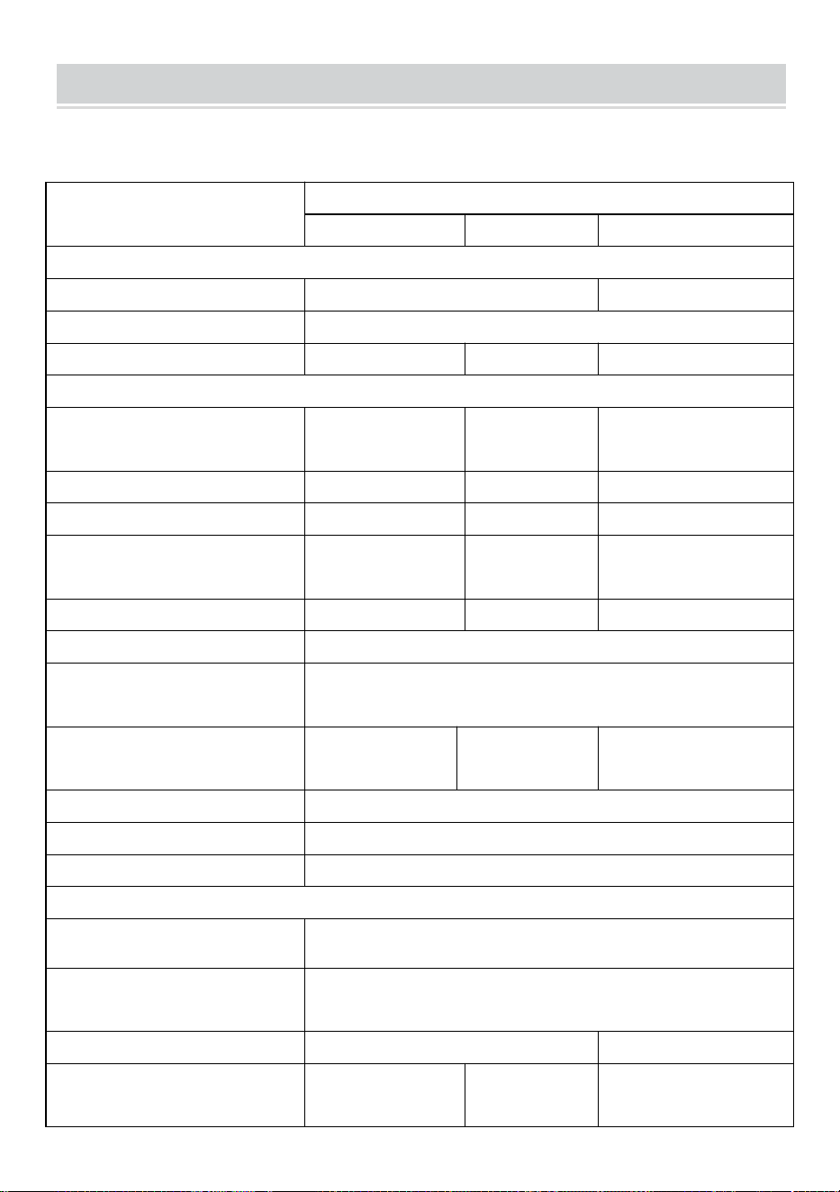
- 5 -
SPECIFICATIONS
Jesteś Zapraszamy do wyboru naszych produktów w postaci mikroinwerterów
słonecznych podłączonych do sieci .
Dane specyfikacji
Model
GT-600
GT-800
GT-1200
Dane wejściowe (prąd stały, fotowoltaika)
Liczba złączy wejściowych MC4
2 zestawy
4 zestawy
Zakres napięcia roboczego
Prąd stały 18 V-50 V
Maksymalny prąd wejściowy
12A*2
14A*2
16A*2
Dane wyjściowe (AC)
Typ sieci jednofazowej
prąd zmienny 230
V
prąd zmienny
230 V
Prąd zmienny 110 V lub
prąd zmienny 230 V
Maksymalna moc wyjściowa
600 W
800 W
1200 W
Prąd wyjściowy znamionowy
2,6 A
3,5 A
10,9 A lub 5,2 A
Nominalne napięcie wyjściowe
prąd zmienny 230
V
prąd zmienny
230 V
Prąd zmienny 110 V lub
prąd zmienny 230 V
Zakres częstotliwości wyjściowej
50 Hz
50 Hz
60Hz lub 50Hz
Współczynnik mocy
≥0,99%
Całkowite zniekształcenie
harmoniczne
Całkowite zniekształcenia harmoniczne <5%
Maksymalna liczba jednostek na
oddział
@230VAC: 4
jednostki
@230VAC: 3
jednostki
@ 110 VAC: 2 jednostki lub
@230VAC: 3 jednostki
Maksymalna wydajność
95%
Nominalna sprawność MPPT
99,5%
Pobór mocy w nocy
≤1W
Dane mechaniczne
Zakres temperatury otoczenia
podczas pracy
-40℃ do +65℃
Zakres temperatur
przechowywania
-40°C do +85°C
Wymiary (szer. * wys. * gł.)
305 * 186 * 44 mm
490 x 254 x 50 mm
Stopień wodoodporności
IP67
IP65/IP67
(Proszę
IP67
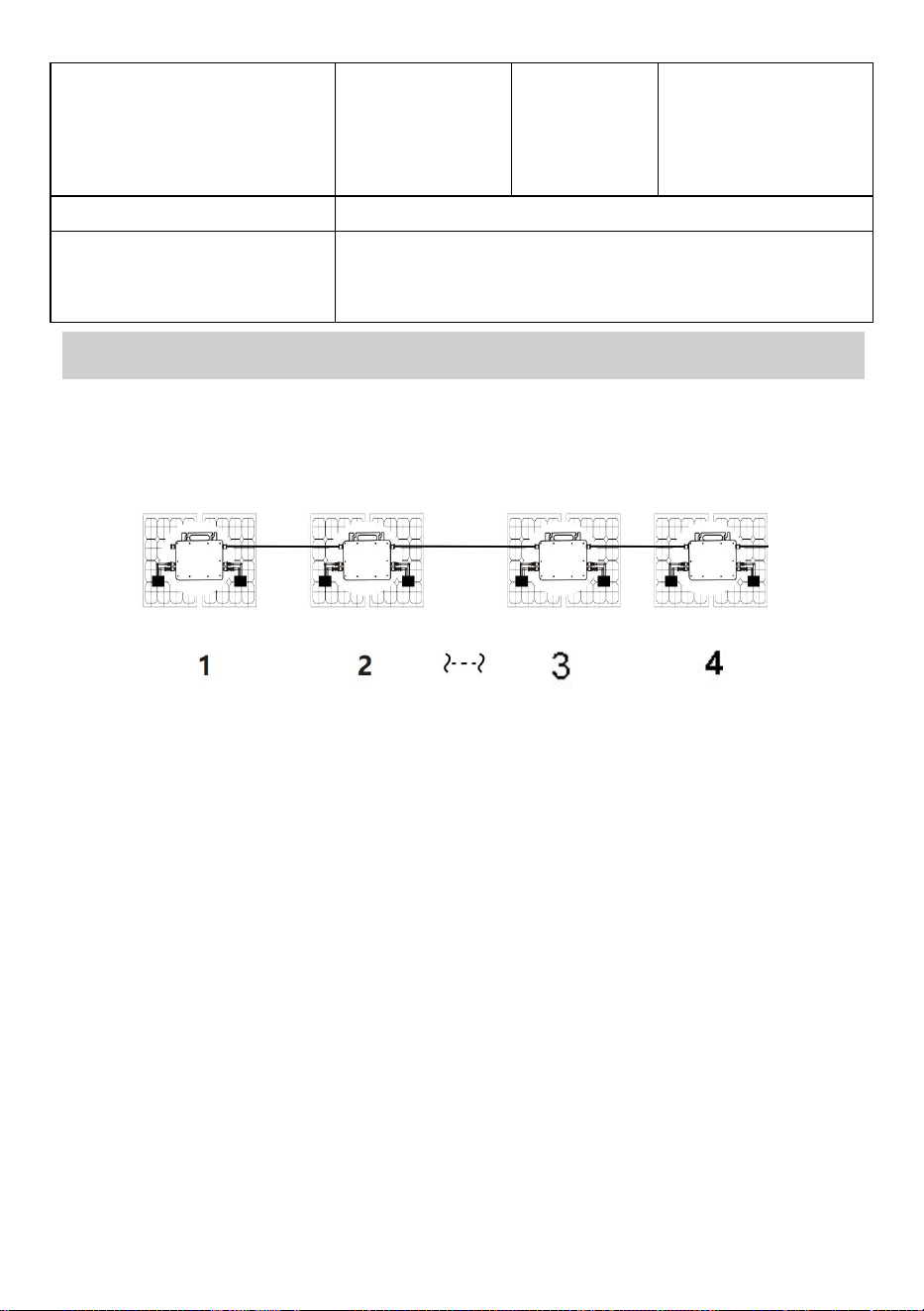
- 6 -
zapoznać się z
informacjami
na tabliczce
znamionowej
produktu)
Komunikacja
WIFI (monitorowanie w chmurze)
Funkcje ochronne
Ochrona wyspy izolowanej, ochrona napięcia
Ochrona częstotliwości
Zabezpieczenia temperaturowe, zabezpieczenia prądowe itp.
INSTALLATION SCHEMATIC
Jednofazowa metoda montażu równoległego mikro falownik
GT-600
16. @Sieć jednofazowa 230 V Maksymalnie 4 jednostki 600 W Micro falowników
na gałąź.
17. Maksymalna moc wejściowa DC każdego falownika wynosi 600 W
(maksymalna moc wyjściowa modułu PV)
moc wynosi 2x300W) .
18. Napięcie VOC modułów fotowoltaicznych nie powinno być większe niż
maksymalne napięcie wejściowe DC
Mikro falowniki .
GT-800
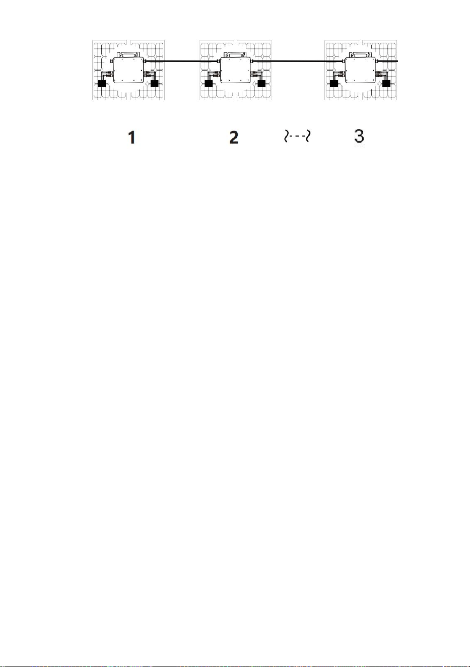
- 7 -
16. @Sieć jednofazowa 230 V Maksymalnie 3 jednostki 8 00W Micro falowników
na gałąź.
17. Maksymalna moc wejściowa DC każdego falownika wynosi 800 W
(maksymalna moc wyjściowa modułu PV)
moc wynosi 2x 400W ) .
18. Napięcie VOC modułów fotowoltaicznych nie powinno być większe niż
maksymalne napięcie wejściowe DC
Mikro falowniki .
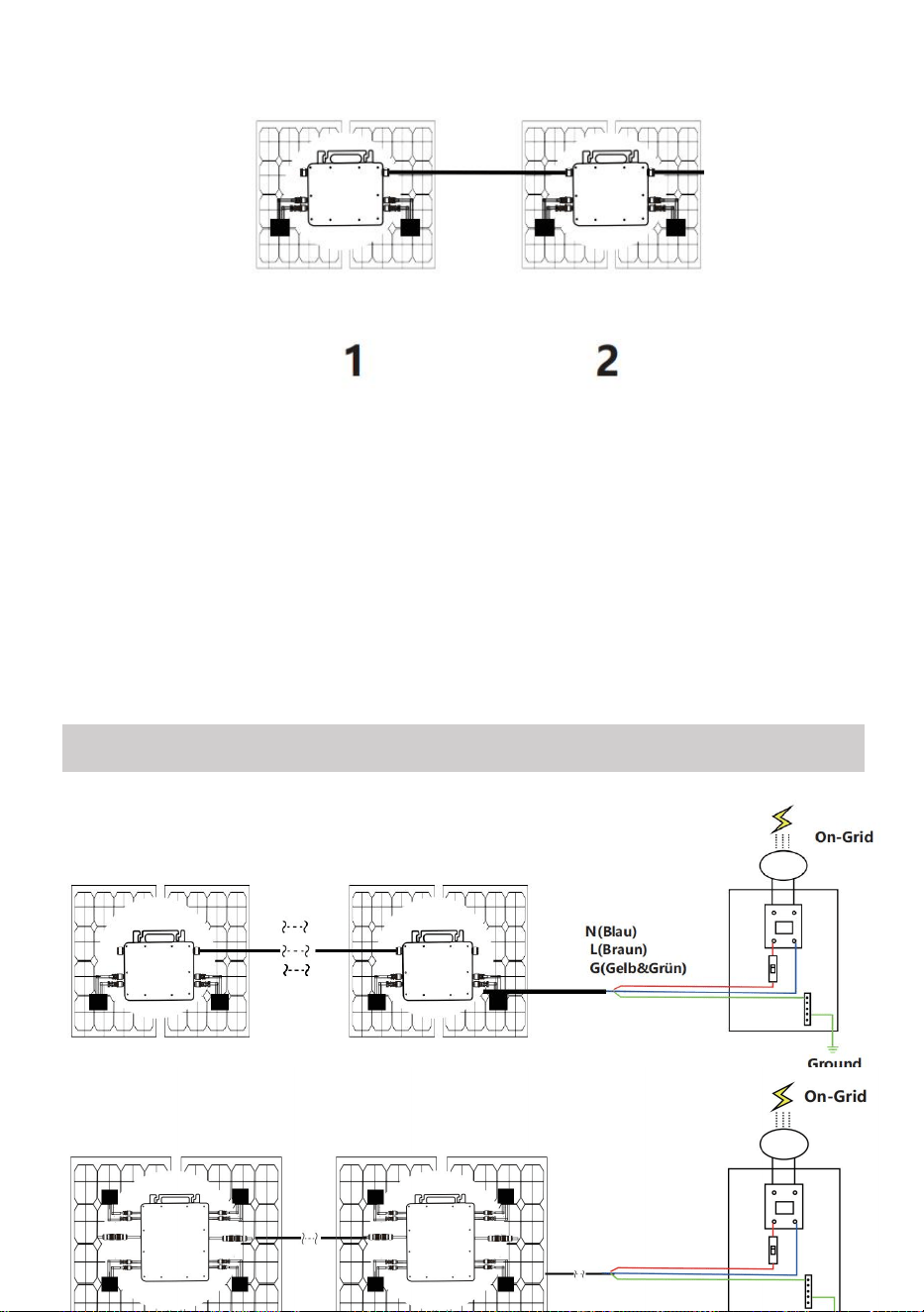
- 8 -
GT-1200
16. Sieć jednofazowa 110 V Maksymalnie 2 jednostki lub @Sieć jednofazowa 230
V
Maksymalnie 3 jednostki 12 00W Micro falowników na gałąź.
17. Maksymalna moc wejściowa DC każdego falownika wynosi 12 00 W
(maksymalna moc wyjściowa modułu fotowoltaicznego)
moc wynosi 2x 6 00W) .
18. Napięcie VOC modułów fotowoltaicznych nie powinno być większe niż
maksymalne napięcie wejściowe DC
Mikro falowniki .
WIRING SCHEMATIC
Jednofazowa metoda podłączenia mikroinwertera
GT-600/GT-800
GT-1200
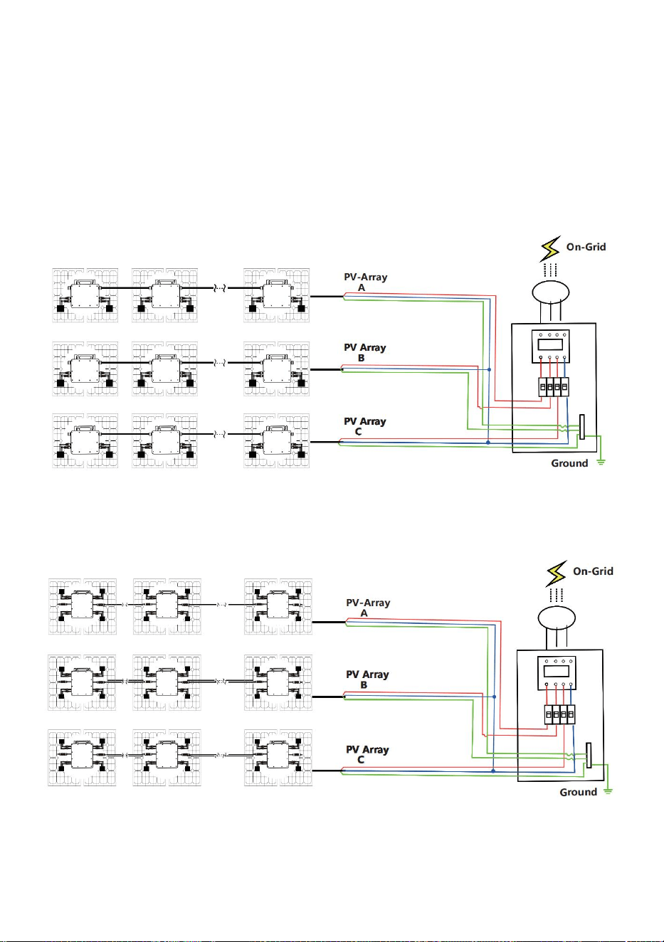
- 9 -
Trójfazowa metoda podłączenia mikroinwertera
GT-600/GT-800
GT-1200

- 10 -
31. Środki ostrożności
Należy pamiętać, że podczas podłączania mikroinwertera istnieje ryzyko
porażenia prądem!
Mikroinwerter nagrzewa się podczas pracy! Chroń się
odpowiednio od oparzeń !
Przed skonfigurowaniem monitorowania chmury WiFi należy poprawnie
zainstalować mikroinwerter i spraw, żeby działało normalnie .
Jak Urządzenie mobilne (smartfon lub tablet) z funkcją Bluetooth i
systemem Android lub innym oraz bezprzewodowe urządzenie sieciowe,
np. router bezprzewodowy, który może zapewnić sieć WiFi i dostęp do
Internetu .
Aby skonfigurować monitorowanie chmury WLAN, najpierw włącz
funkcję Bluetooth w urządzeniu inteligentnym.
Upewnij się, że Twoje urządzenie inteligentne korzysta z tej samej sieci
Wi-Fi co konfigurowany mikroinwerter i że może ono łączyć się z
urządzeniami sieci bezprzewodowej oraz uzyskiwać dostęp do Internetu
w tej samej lokalizacji co mikroinwerter .
Upewnij się, że odległość między urządzeniem sieci bezprzewodowej a
mikroinwerterem nie przekracza 20 m i że nie ma żadnych przeszkód lub
jest ich niewiele.
32. Opis sprzętu
MICRO INVERTER WIFI CLOUD MONITORING
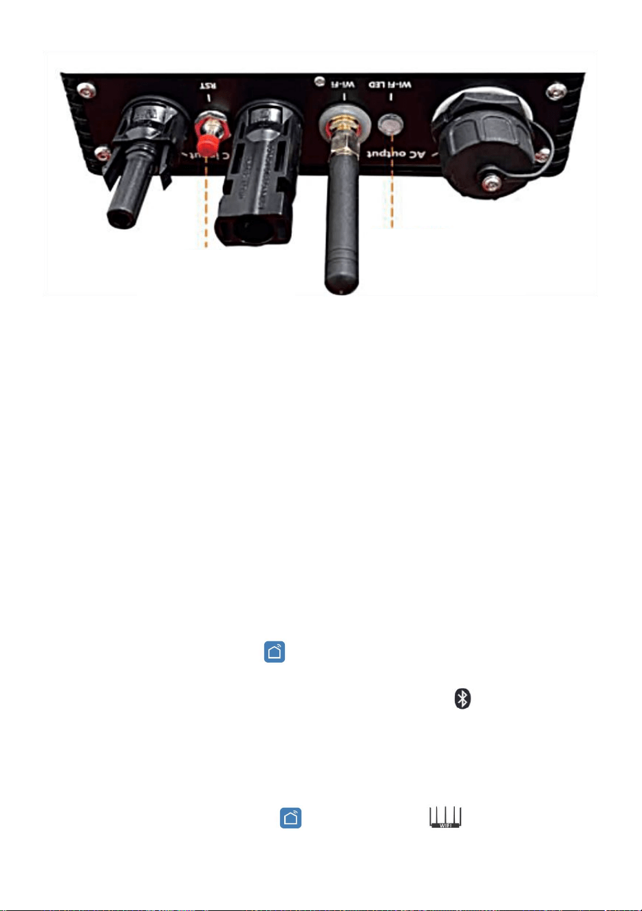
- 11 -
33. Dioda LED stanu WIFI
Niebieskie światło miga po włączeniu = moduł monitorujący chmurę WiFi
oczekuje na konfigurację.
Niebieskie światło wyłączone po włączeniu = moduł monitorowania
chmury WiFi uruchamia się i przechodzi do normalnego trybu pracy.
Niebieskie światło miga = sieć nie jest skonfigurowana lub sieć nie może
połączyć się z urządzeniem sieciowym bezprzewodowym, lub
mikroinwerter został usunięty z chmury.
Brak światła = monitorowanie chmury WiFi działa normalnie .
34. Przygotowanie przed konfiguracją i użytkowaniem
Zainstaluj mikroinwerter prawidłowo i spraw, aby działał normalnie,
generując energię.
Pobierz i zainstaluj Lub Aplikację „ Smart Life ” można znaleźć,
wyszukując ją w odpowiednim sklepie z aplikacjami dla systemu
Android lub Apple.
Włącz funkcję Bluetooth w swoim urządzeniu inteligentnym .
Sprawdź, czy Twoje urządzenie sieciowe bezprzewodowe (np. router
bezprzewodowy) działa prawidłowo i jest połączone z Internetem .
Użyj swojego inteligentnego urządzenia ( Lub „Inteligentne życie”
WIFI
Set/Reset Button
WIFI Status
LED Indicator

- 12 -
Aplikacja zainstalowana) w miejscu instalacji mikroinwertera, aby
połączyć się z urządzeniem sieci bezprzewodowej. Jeśli masz normalny
dostęp do Internetu , postępuj zgodnie z instrukcjami dotyczącymi
konfiguracji i użytkowania podanymi na następnej stronie.
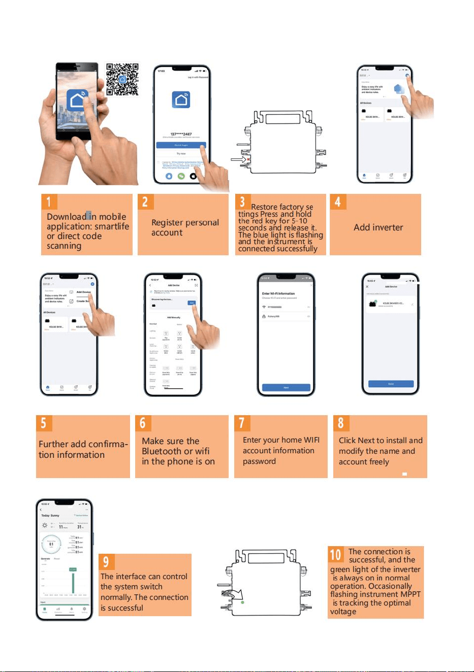
- 13 -
35. Kroki konfiguracji monitoringu w chmurze WIFI .
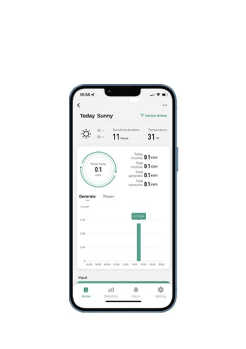
- 14 -
36. Korzystanie z aplikacji WIFI Cloud Monitoring .
Modyfikuj nazwę urządzenia
Kliknij urządzenie, które chcesz zmodyfikować, na liście urządze ń na
stronie głównej, aby przejść na stronę ze szczegółowymi informacjami o
urządzeniu (rysunek 5).
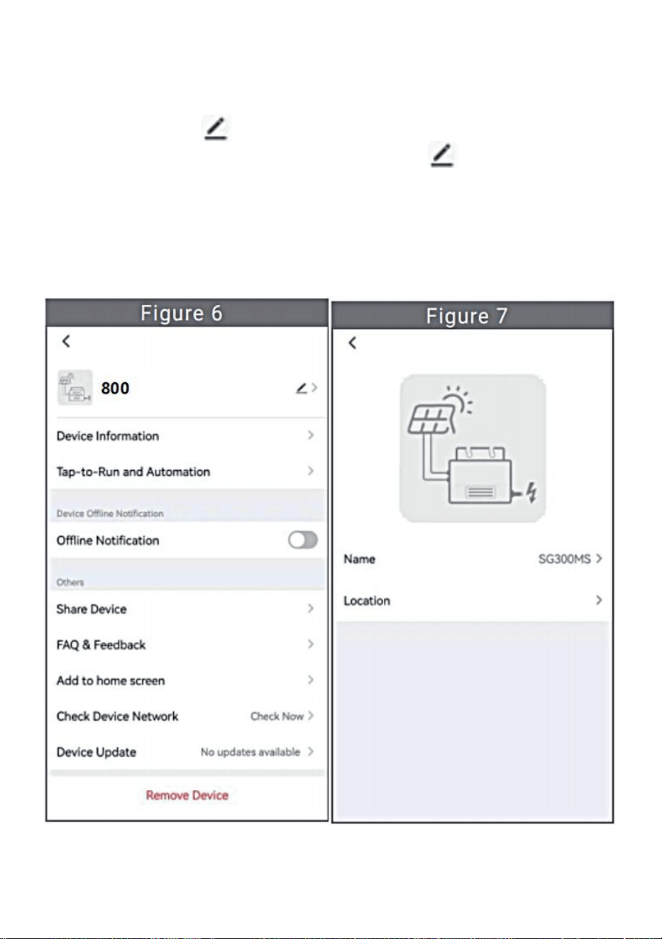
- 15 -
Kliknij przycisk w prawym górnym rogu, aby przejść do strony
ustawień urządzenia (rysunek 6), kliknij przycisk górny Przejdź do
strony z nazwą i stanowiskiem (Rysunek 7), kliknij pozycję „Nazwa”, a
następnie wprowadź nową nazwę i zapisz ją (Rysunek 8).

- 16 -
Usuń urządzenie
Kliknij urządzenie, które chcesz usunąć, na liście urządze ń na stronie
głównej, aby wprowadzić informacje o urządzeniu strona ze
szczegółami (rysunek 5).
Kliknij przycisk w prawym górnym rogu, aby przejść do strony
ustawień urządzenia (rysunek 6). Kliknij przycisk „Usuń urządzenie”
poniżej (rysunek 9), a następnie kliknij przycisk „Rozłącz”, aby usuń
urządzenie lub kliknij przycisk „Odłącz i wyczyść dane”, aby usunąć
urządzenie i jednocześnie wyczyścić wszystkie dane zapisane przez
urządzenie w chmurze.
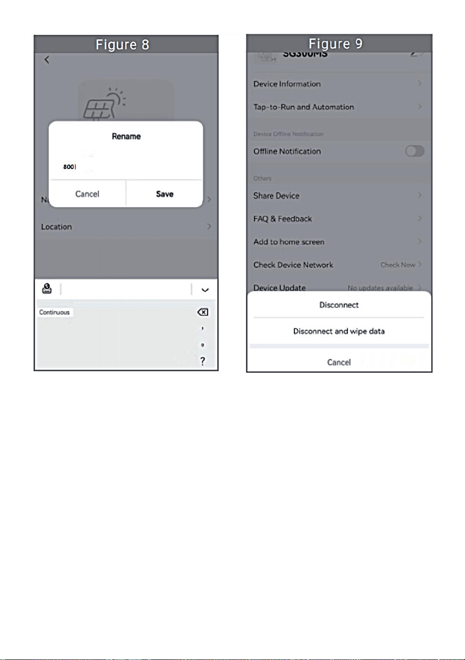
- 17 -

- 18 -
Udostępnij urządzenie innym
Kliknij urządzenie, które chcesz udostępnić, na liście urządze ń na
stronie głównej, aby przejść na stronę ze szczegółowymi informacjami o
urządzeniu (rysunek 5).
Kliknij przycisk w prawym górnym rogu, aby wejść strona ustawie ń
urządzenia (rysunek 6).
Kliknij opcję „ Udostępnij urządzenie ” , aby wprowadzić urządzenie
strona udostępniania (Rysunek 10) , kliknij przycisk aby
przejść na stronę „ Dodaj udostępnianie ” (Rysunek 11) i wybierz
najlepszy sposób udostępniania, który uważasz za najskuteczniejszy
wygodne udostępnianie łącza do mikroinwertera.
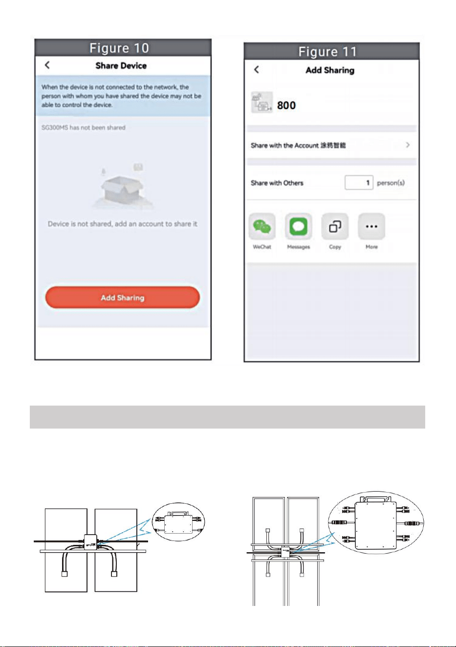
- 19 -
31. Proces instalacji polegający na zamocowaniu falownika do uchwytu PV
z mocowaniem
śruby przedstawiają się następująco:
INSTRUCTIONS FOR INSTALLATION WIRING
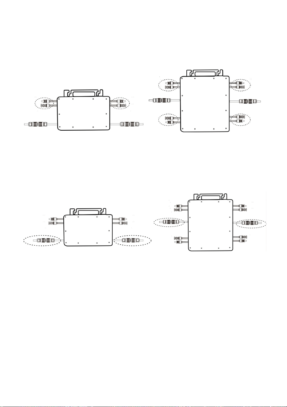
- 20 -
GT-600/800 GT-1200
32. Podłącz prąd stały PV do falownika i zwróć uwagę na rozróżnienie
między dodatnim i ujemnym, jak pokazano poniżej:
GT-600/800 GT-1200
33. Otwórz wodoodporną pokrywę po stronie wyjścia prądu przemiennego
mikroinwertera,
a następnie podłącz go do AC. W następujący sposób:
GT-600/800 GT-1200
34. Powtórz kroki od 1 do 3, aby dokończyć instalację mikroinwertera.
35. Podłącz wiele inwerterów za pomocą kabli wyjściowych prądu
przemiennego.
36. Główny kabel prądu przemiennego jest podłączony do sieci
energetycznej.
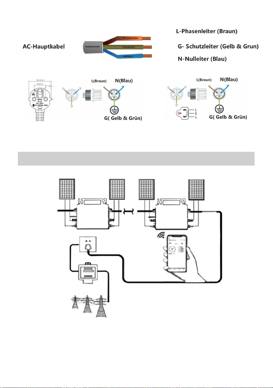
- 21 -
Prąd zmienny 230 V 50 Hz Prąd zmienny 110 V 60 Hz
SCHEMATIC DIAGRAM OF THE COMPLETION OF THE INSTALLATION

- 22 -
GT-600/800
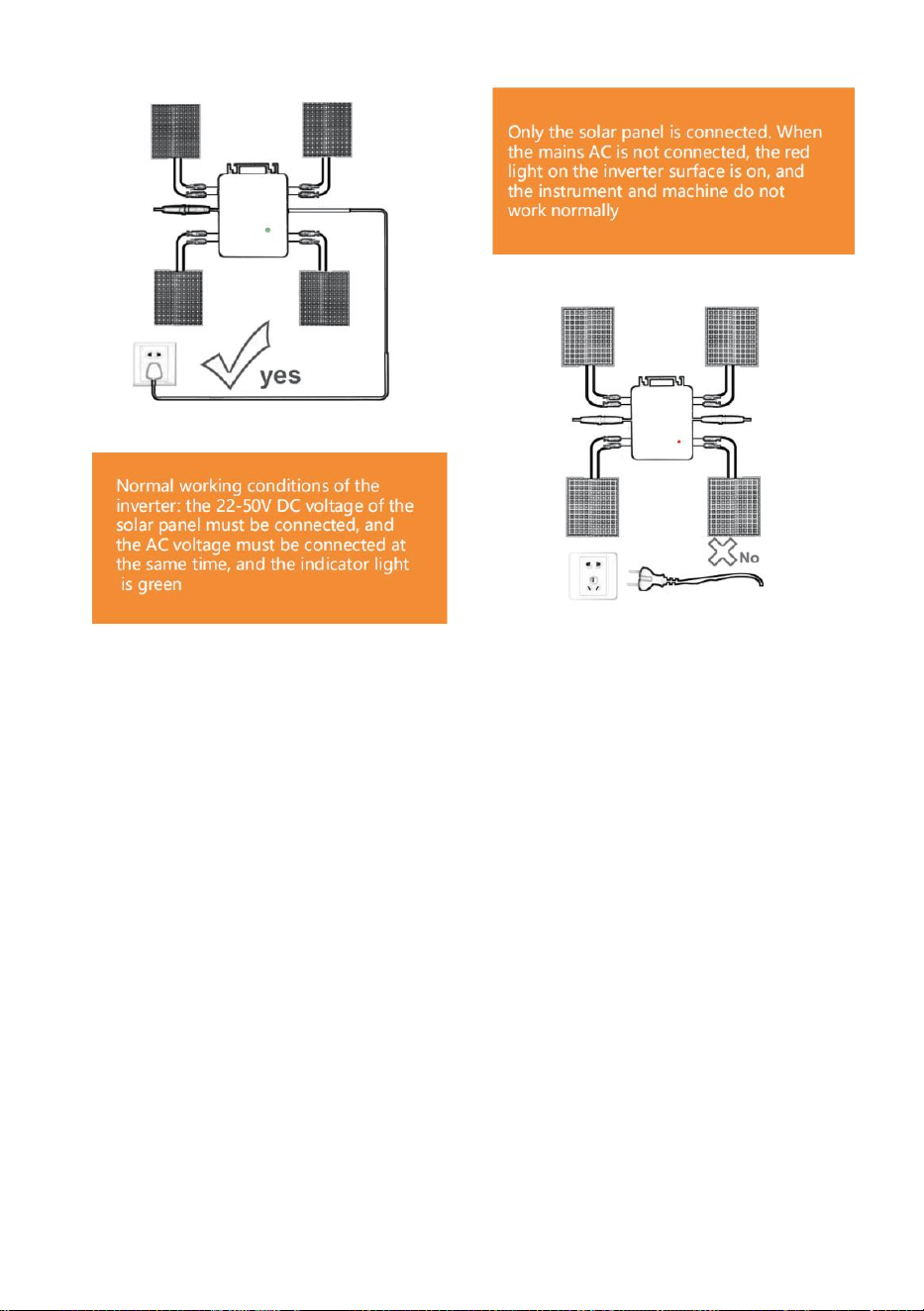
- 23 -
GT-1200
Notatka:
Gdy falownik zostanie zakupiony po raz pierwszy i podłączony do
telefon komórkowy do monitorowania, wystarczy włączyć zasilanie sieciowe
AC, niebieskie światło obok niego miga, a falownik można połączyć przez
WIFI lub parowanie Bluetooth. Gdy falownik można kontrolować za pomocą
telefonu komórkowego, wskazuje to, że połączenie jest normalne.

- 24 -
56. CO ZROBIĆ, GDY Smart-App nie może znaleźć mikroinwertera, którego
ma użyć
w dodatku?
Sprawdź następujące punkty:
Sprawdź, czy wskaźnik stanu WiFi mikroinwertera miga na niebiesko .
Sprawdź, czy funkcja Bluetooth w Twoim urządzeniu inteligentnym jest
włączona .
Sprawdź czy sygnał sieci bezprzewodowej jest dobry.
Jeżeli wszystkie powyższe przypadki mają miejsce, a falownik nadal nie
został znaleziony, naciśnij czerwony przycisk resetowania na dłużej niż 5
sekund, aby reset. Po ponownym zaświeceniu się niebieskiej kontrolki WiFi,
użyj aplikacji „Smart Life”, aby ponownie skonfigurować sieć.
57. CO ZROBIĆ, jeśli muszę skonfigurować wiele mikroinwerterów?
Zainstaluj wszystkie mikroinwertery prawidłowo i spraw, aby działały
normalnie, generując energię, a następnie działać zgodnie z konfiguracją i
korzystając z kroków. Aplikacja może wyszukiwać wszystkie falowniki,
które mają zostać dodane jednocześnie i skonfigurować je jednocześnie.
58. CO ZROBIĆ, jeśli identyfikator SSID mojej sieci Wi-Fi lub hasło ulegną
zmianie?
Skonfiguruj ponownie falownik zgodnie z konfiguracją i poniższymi
krokami.
59. CO ZROBIĆ, JEŚLI kontrolka stanu WiFi falownika zgaśnie, ale
urządzenie wyświetlane na aplikacja nie jest online?
Oznacza to, że możesz połączyć się z urządzeniem sieciowym
bezprzewodowym, ale nie możesz połączyć się z chmurą serwer. Oznacza
to, że Twoje urządzenie sieci bezprzewodowej nie może połączyć się z
Internetem. Upewnij się, że Twoje Internet działa prawidłowo.

- 25 -
60. Miejsce instalacji falownika nie jest tymczasowo wyposażone w
router i nie ma sygnału WiFi ?
W jaki sposób aplikacja łączy się z falownikiem i sprawdza, czy działa
on prawidłowo?
Możesz użyć bezczynnego smartfona, aby otworzyć udostępnianie
sygnału WiFi w punkcie dostępowym telefonu komórkowego
połączenie i ponownie skonfiguruj połączenie sieciowe po
zainstalowaniu routera.
61. Wokół jest wiele sygnałów WiFi. Czy możemy połączyć różne
sygnały WiFi?
Nie, połączenie WiFi mikroinwertera i smartfona musi być spójne, aby
można było skonfigurować sieć.
62. Czy aplikacja może skonfigurować mikroinwerter w różnych
miejscach? Czy mogę przeglądać dane w różnych miejscach?
Nie można konfigurować mikroinwertera w różnych miejscach, ale
można przeglądać dane w różnych miejscach. Inwerter przesyła
najnowsze dane o stanie do serwera w chmurze co 3–5 minut.
63. Po sprawdzeniu, że nie ma żadnego problemu, aplikacja nadal nie
może znaleźć mikroinwertera.
Aby zresetować falownik, naciśnij i przytrzymaj czerwony przycisk
falownika przez ponad 5 sekund.
Gdy wskaźnik WiFi ponownie zacznie migać, użyj aplikacji, aby
ponownie skonfigurować sieć.
64. CO ZROBIĆ, jeśli chcę monitorować ten sam falownik na dwóch
lub więcej urządzeniach inteligentnych?
Możesz udostępnić falownik innemu telefonowi korzystając z funkcji
udostępniania urządzenia.
65. Czy dane aplikacji zostaną zapisane?

- 26 -
Tak, dane aplikacji będą przechowywane na serwerze w chmurze. Po
pomyślnym skonfigurowaniu sieci możesz przeglądać dane w dowolnym
czasie i miejscu.
66. Nie można połączyć falownika z aplikacją w nocy?
W nocy, ponieważ panele słoneczne nie generują prądu, mikroinwerter
nie pobiera prądu. Pozostaje więc w trybie offline i nie ma możliwości
ponownej konfiguracji sieci.
ACCESSORIES LIST
26.Instrukcja obsługi *1
27.Przewód zasilający podłączony do sieci *1
28.Śruba imbusowa o średnicy 8 mm i długości 28 mm + podkładka płaska
+ sprężyna
podkładka + nakrętka *2
29.Śruba z łbem sześciokątnym o średnicy 5 mm i długości 13 mm +
nakrętka *2 (600 W/800 W)
Śruba imbusowa o średnicy 4 mm i długości 8 mm *1 (1200 W)
30.Antena WiFi *1

- 27 -
Producent: Shanghaimuxinmuyeyouxiangongsi
Adres: Shuangchenglu 803nong11hao1602A-1609shi, baoshanqu,
szanghaj 200000 CN.
Importowane do AUS: SIHAO PTY LTD, 1 ROKEVA STREETEASTWOOD
NSW 2122 Australia
Importowane do USA: Sanven Technology Ltd., Suite 250, 9166 Anaheim
Place, Rancho Cucamonga, CA 91730
REP
EC
E-CrossStu GmbH
Mainzer Landstr.69, 60329 Frankfurt am Main.
REP
UK
YH CONSULTING LIMITED.
C/O YH Consulting Limited Office 147, Centurion House,
London Road, Staines-upon-Thames, Surrey, TW18 4AX


- 29 -
Technisch Ondersteuning en E-garantiecertificaat
www.vevor.com/support
MICRO-OMVORMER
MODEL: GT-600/GT-800/GT-1200
We continue to be committed to provide you tools with competitive price.
"Save Half", "Half Price" or any other similar expressions used by us only represents an
estimate of savings you might benefit from buying certain tools with us compared to the major
top brands and does not necessarily mean to cover all categories of tools offered by us. You
are kindly reminded to verify carefully when you are placing an order with us if you are
actually saving half in comparison with the top major brands.

- 1 -
MODEL: GT-600/GT-800/GT-1200
GT-600/GT-800 GT-1200
Have product questions? Need technical support? Please feel free to
contact us:
Technical Support and E-Warranty Certificate
www.vevor.com/support
NEED HELP? CONTACT US!
This is the original instruction, please read all manual instructions
carefully before operating. VEVOR reserves a clear interpretation of our
user manual. The appearance of the product shall be subject to the
product you received. Please forgive us that we won't inform you again if
there are any technology or software updates on our product.
MICRO INVERTER
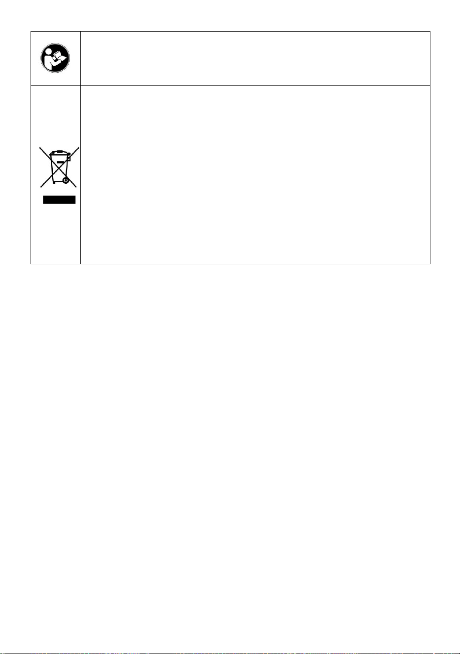
- 2 -
Waarschuwing: om het risico op letsel te verkleinen, moet de
gebruiker de gebruiksaanwijzing zorgvuldig lezen.
Dit product is onderworpen aan de bepalingen van de
Europese richtlijn 2012/19/EG. Het symbool met een
doorgestreepte afvalbak geeft aan dat het product in de
Europese Unie gescheiden afvalinzameling vereist. Dit geldt
voor het product en alle accessoires die met dit symbool zijn
gemarkeerd. Producten die als zodanig zijn gemarkeerd,
mogen niet met het normale huishoudelijke afval worden
weggegooid, maar moeten worden ingeleverd bij een
inzamelpunt voor recycling van elektrische en elektronische
apparaten.
WAARSCHUWING: GEVAAR VOOR ELEKTRISCHE SCHOK
Het product wordt gebruikt in combinatie met een permanente energiebron
(batterij). Zelfs als het apparaat is uitgeschakeld, kan er een gevaarlijke
elektrische spanning kan optreden bij de ingangs- en/of uitgangsklemmen.
Schakel altijd de wisselstroom uit en koppel de accu los voordat u
Onderhoud uitvoeren.
Het product bevat geen interne onderdelen die door de gebruiker
onderhouden kunnen worden. Verwijder het voorpaneel niet en neem het
product niet in gebruik tenzij alle panelen zijn gemonteerd. Alle onderhoud
moet worden uitgevoerd door gekwalificeerd personeel.
Gebruik het product nooit op plekken waar gas- of stofexplosies kunnen
optreden. Raadpleeg de specificaties van de fabrikant van het product.
batterij om ervoor te zorgen dat de batterij geschikt is voor gebruik met dit
product. De veiligheidsinstructies van de batterijfabrikant moeten altijd
worden waargenomen.
WAARSCHUWING: til geen zware voorwerpen zonder hulp.
Installatie
Lees de installatie-instructies voordat u met de installatie begint.

- 3 -
Dit product is een apparaat van veiligheidsklasse I (geleverd met een
aardingsklem voor veiligheidsdoeleinden). De AC-ingangs- en/of
uitgangsklemmen moet worden voorzien van een ononderbroken aarding
voor veiligheidsdoeleinden. Een extra aardingspunt bevindt zich aan de
buitenkant van het product. Als kan worden aangenomen dat de
aardingsbeveiliging beschadigd is, moet het product buiten gebruik worden
gesteld en voorkomen dat het apparaat onbedoeld opnieuw in gebruik
wordt genomen; neem contact op met gekwalificeerd
onderhoudspersoneel.
Zorg ervoor dat de verbindingskabels zijn voorzien van zekeringen en
stroomonderbrekers. Vervang nooit een beschermingsapparaat door een
onderdeel van een
ander type. Raadpleeg de handleiding voor het juiste onderdeel.
Controleer voordat u het apparaat inschakelt of de beschikbare
spanningsbron overeenkomt met de configuratie-instellingen van het
product. zoals beschreven in de handleiding.
Zorg ervoor dat de apparatuur onder de juiste bedrijfsomstandigheden
wordt gebruikt. Gebruik het nooit in een natte of stoffige omgeving.
Zorg ervoor dat er altijd voldoende vrije ruimte rondom het product is voor
ventilatie en dat de ventilatieopeningen niet geblokkeerd zijn.
Installeer het product in een hittebestendige omgeving. Zorg er daarom
voor dat er geen chemicaliën, plastic onderdelen, gordijnen of andere
textiel, etc. aanwezig zijn.
in de directe omgeving van de apparatuur.
Transport en opslag
Zorg ervoor dat de netvoeding en de accukabels losgekoppeld zijn
wanneer u het product opbergt of vervoert.
Er wordt geen aansprakelijkheid aanvaard voor schade tijdens het
transport indien het apparaat niet in de originele verpakking wordt
vervoerd.
Bewaar het product in een droge omgeving; de bewaartemperatuur moet
variëren van –40°C tot 65 ° C.
Raadpleeg de handleiding van de fabrikant van de batterij voor informatie

- 4 -
over het transporteren, opslaan, opladen, herladen en afvoeren van de
batterij.
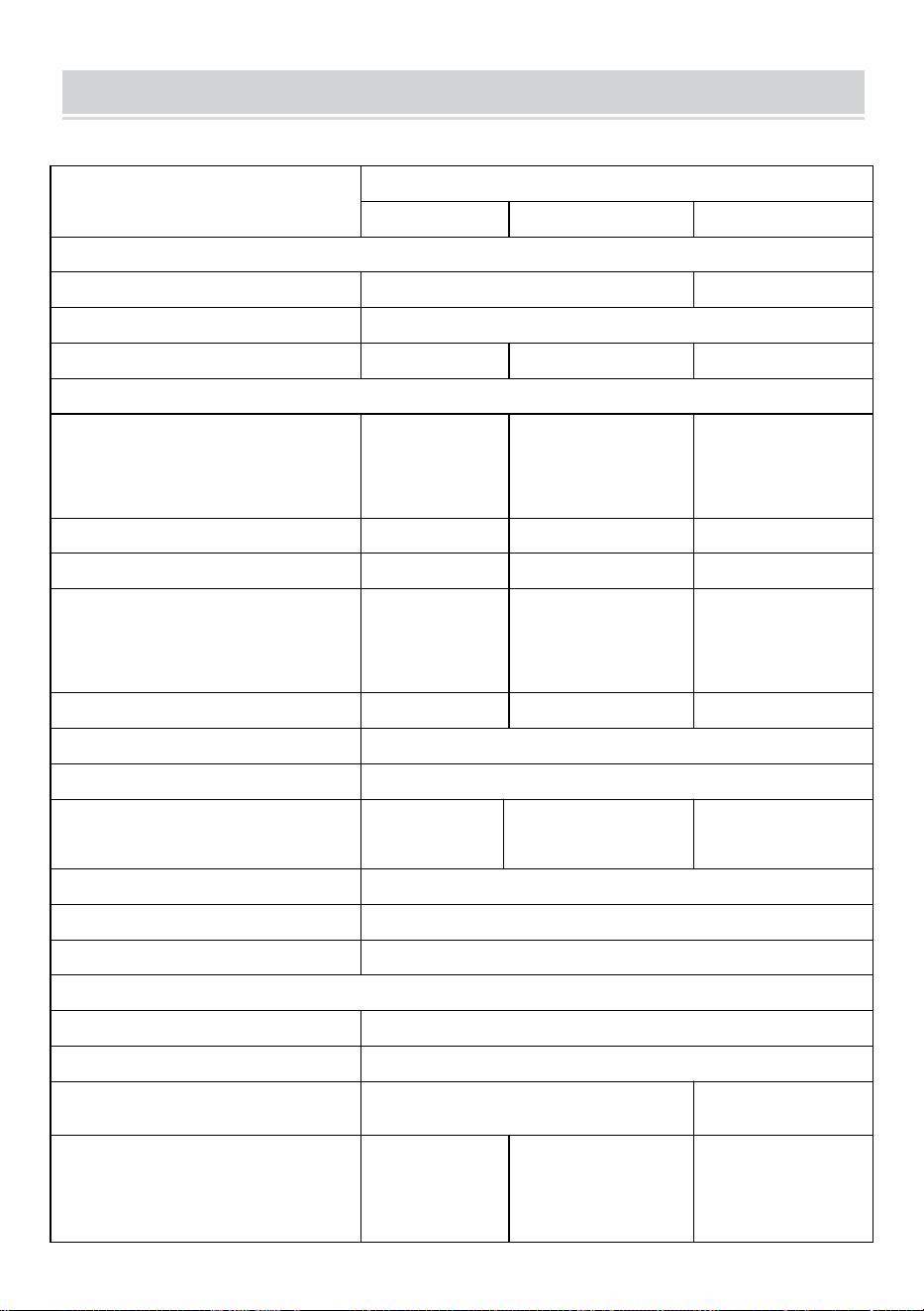
- 5 -
SPECIFICATIONS
Jij bent Welkom bij onze microgrid-gekoppelde zonneomvormerproducten .
Specificatiegegevens
Model
GT-600
GT-800
GT-1200
Invoergegevens (DC, PV)
Aantal ingangen MC4-connector
2 sets
4 sets
Werkingsspanningsbereik
DC18V-50V
Maximale ingangsstroom
12A*2
14A*2
16A*2
Uitvoergegevens (AC)
Enkelfasig nettype
AC230V
AC230V
Wisselstroom 110V
of wisselstroom
230V
Maximaal uitgangsvermogen
600W
800W
1200W
Nominale uitgangsstroom
2.6 Een
3,5 Een
10,9A of 5,2A
Nominale uitgangsspanning
AC230V
AC230V
Wisselstroom 110V
of wisselstroom
230V
Uitgangsfrequentiebereik
50Hz
50Hz
60 Hz of 50 Hz
Vermogensfactor
≥0,99%
Totale harmonische vervorming
Totale vochtigheidsgraad <5%
Maximale eenheden per vestiging
@230VAC: 4
eenheden
@230VAC: 3 eenheden
@ 110 VAC: 2 eenheden Of @
230VAC: 3 eenheden
Maximale efficiëntie
95%
Nominale MPPT-efficiëntie
99,5%
Stroomverbruik 's nachts
≤1W
Mechanische gegevens
Bedrijfsomgevingstemperatuurbereik
-40℃ tot +65℃
Opslagtemperatuurbereik
-40°C tot +85C
Afmetingen (B*H*D)
305 * 186 * 44mm
490 * 254 *
50mm
Waterdichtheidsgraad
IP67
IP65/IP67
(Raadpleeg de
informatie op het
productnaamplaatje)
IP67
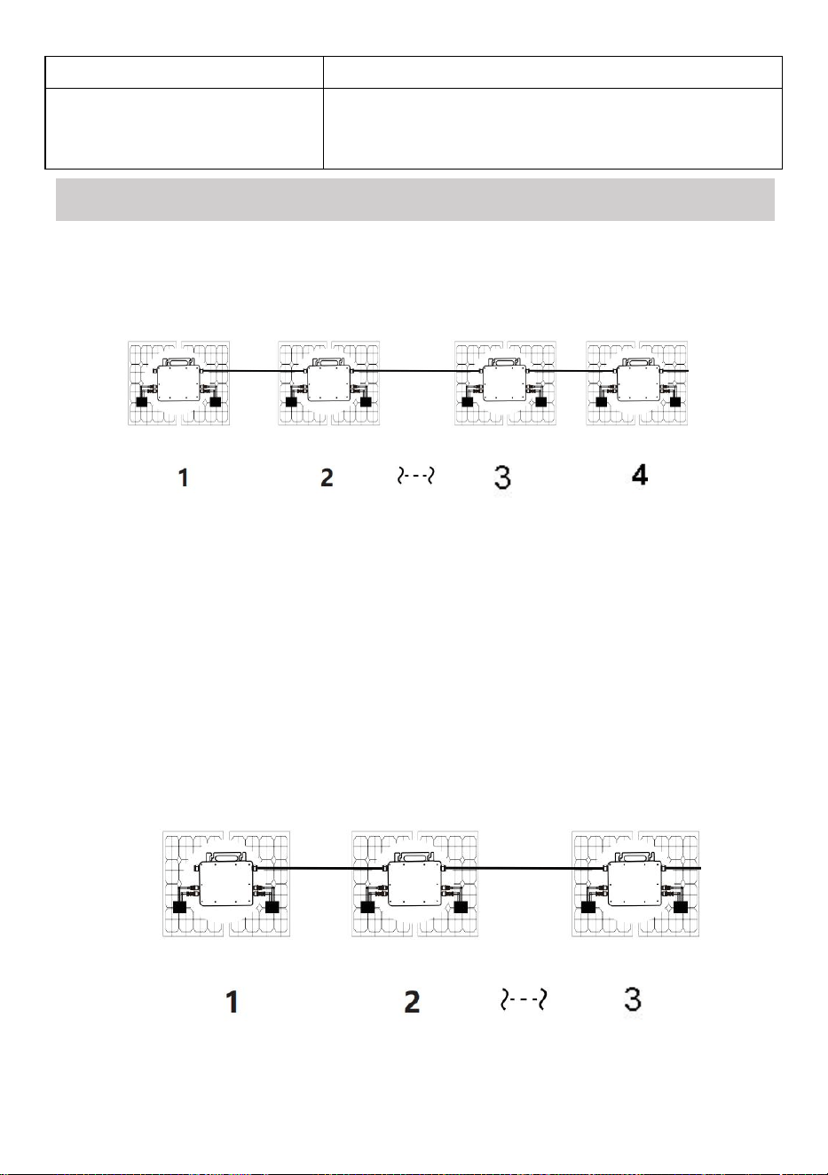
- 6 -
Mededeling
WIFI (Cloudbewaking)
Beschermingsfuncties
Geïsoleerde eilandbeveiliging, spanningsbeveiliging
Frequentiebeveiliging
Temperatuurbeveiliging, stroombeveiliging, enz.
INSTALLATION SCHEMATIC
Enkelfasige parallelle montagemethode van micro omvormer
GT-600
19. @Enkele fase 230V net Maximaal 4 eenheden 600W Micro omvormers per
vestiging.
20. Het maximale DC-ingangsvermogen van elke omvormer is 600 W (het
maximale uitgangsvermogen van de PV-module)
vermogen bedraagt 2x300W) .
21. De VOC van PV-modules mag niet groter zijn dan de maximale
DC-ingangsspanning
van Micro omvormers .
GT-800
19. @Enkele fase 230V net Maximaal 3 eenheden 8 00W Micro omvormers per
vestiging.

- 7 -
20. Het maximale DC-ingangsvermogen van elke omvormer is 800 W (het
maximale uitgangsvermogen van de PV-module).
vermogen is 2x 4 00W) .
21. De VOC van PV-modules mag niet groter zijn dan de maximale
DC-ingangsspanning
van Micro omvormers .

- 8 -
GT-1200
19. @Enkele fase 110 V net Maximaal 2 units of @Enkele-fase 230V net
Maximaal 3 eenheden 12 00W Micro omvormers per vestiging.
20. Het maximale DC-ingangsvermogen van elke omvormer is 12.000 W (het
maximale uitgangsvermogen van de PV-module).
vermogen is 2x 6 00W) .
21. De VOC van PV-modules mag niet groter zijn dan de maximale
DC-ingangsspanning
van Micro omvormers .
WIRING SCHEMATIC
Enkelfasige aansluitmethode van micro-omvormer
GT-600/GT-800
GT-1200
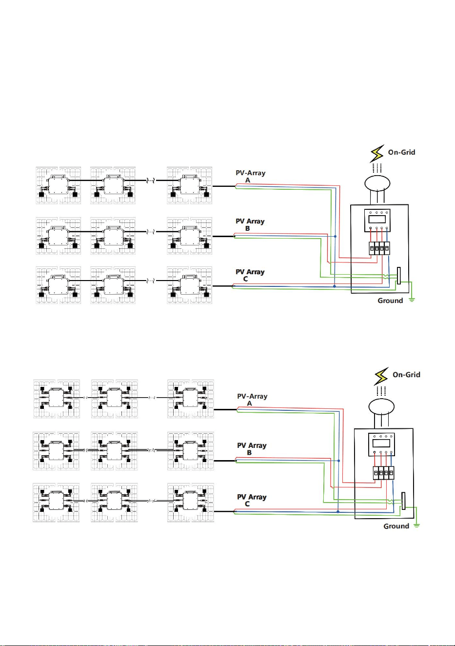
- 9 -
Driefasen aansluitmethode van micro-omvormer
GT-600/GT-800
GT-1200
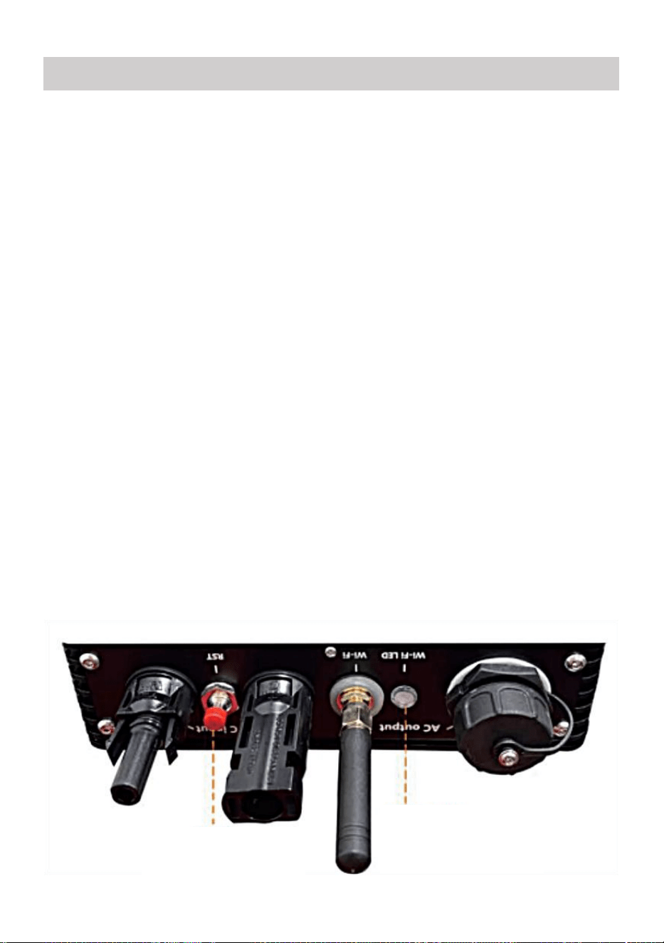
- 10 -
37. Voorzorgsmaatregelen
Houd er rekening mee dat er bij het aansluiten van de micro-omvormer
gevaar voor een elektrische schok bestaat!
De micro-omvormer warmt op tijdens de werking! Bescherm uzelf
dus van brandwonden !
Voordat u WiFi-cloudbewaking configureert, moet u de micro-omvormer
correct installeren en zorg dat het normaal werkt .
Als Er moet een apparaat (smartphone of tablet) met Bluetooth-functie
en Android of een ander systeem beschikbaar zijn , en er moet een
draadloos netwerkapparaat beschikbaar zijn, bijvoorbeeld een
draadloze router die WiFi en internetdiensten kan leveren .
Om WLAN-cloudbewaking te configureren, schakelt u eerst de
Bluetooth-functie van het smart device in.
Zorg ervoor dat uw slimme apparaat hetzelfde wifi-netwerk gebruikt als
de te configureren micro-omvormer en dat het verbinding kan maken
met draadloze netwerkapparaten en toegang heeft tot internet op
dezelfde locatie als de micro-omvormer .
Zorg ervoor dat de afstand tussen het draadloze netwerkapparaat en de
micro-omvormer niet groter is dan 20 m en dat er weinig tot geen
obstakels zijn.
38. Hardwarebeschrijving
MICRO INVERTER WIFI CLOUD MONITORING
WIFI
Set/Reset Button
WIFI Status
LED Indicator
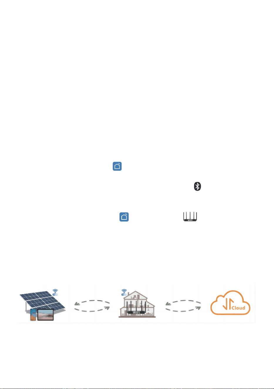
- 11 -
39. WIFI-status-LED
Het blauwe lampje knippert na altijd aan = de
WiFi-cloudbewakingsmodule wacht op configuratie.
Als het blauwe lampje uit is nadat het altijd aan is geweest = de
WiFi-cloudbewakingsmodule start en gaat naar de normale werkstatus.
Het blauwe lampje knippert = het netwerk is niet geconfigureerd, het
netwerk kan geen verbinding maken met het draadloze netwerkapparaat
of de micro-omvormer is verwijderd uit de cloud.
Geen lampje = WiFi-cloudbewaking werkt normaal .
40. Voorbereiding voor configuratie en gebruik
Installeer de micro-omvormer op de juiste manier en zorg ervoor dat
deze normaal werkt om stroom op te wekken.
Download en installeer de of Zoek de app 'Smart Life' in de
bijbehorende Android- of Apple-appstore.
Schakel de Bluetooth-functie van uw smart device in .
Controleer of uw draadloze netwerkapparaat (bijvoorbeeld uw draadloze
router) goed werkt en verbinding heeft met internet .
Gebruik uw slimme apparaat ( of "Slim leven" App geïnstalleerd) op
de installatielocatie van de micro-omvormer om verbinding te maken
met het draadloze netwerkapparaat. Als u normaal toegang hebt tot
internet , volgt u de instructies voor configuratie en gebruik op de
volgende pagina.

- 12 -
41. Configuratiestappen voor WIFI-cloudbewaking .

- 13 -
42. Gebruik van WIFI Cloud Monitoring App .
Apparaatnaam wijzigen
Klik op het apparaat dat u wilt wijzigen in de apparatenlijst op de
startpagina om de pagina met apparaatgegevens te openen (Afbeelding
5).
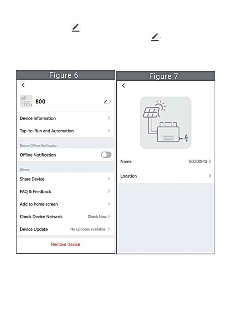
- 14 -
Klik op de knop in de rechterbovenhoek om de pagina met
apparaatinstellingen te openen (Figuur 6), Blijf op de bovenste knop
klikken Ga naar de pagina met naam en positie (Figuur 7), klik op
itemnaam, voer een nieuwe naam in en sla deze op (Figuur 8).

- 15 -
Apparaat verwijderen
Klik op het apparaat dat u wilt verwijderen in de apparatenlijst op de
startpagina om de apparaatgegevens in te voeren detailspagina (Figuur
5).
Klik op de knop rechtsboven om de pagina met apparaatinstellingen
te openen (Afbeelding 6). Klik op de knop 'Apparaat verwijderen'
hieronder (Afbeelding 9), klik op de knop 'Verbinding verbreken' om
Verwijder het apparaat of klik op de knop 'Verbinding verbreken en
gegevens wissen' om het apparaat te verwijderen en tegelijkertijd alle
gegevens te wissen die op het apparaat in de cloud zijn opgeslagen.
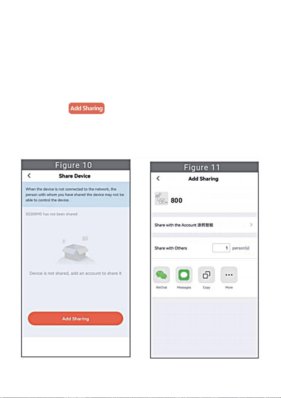
- 16 -
Apparaat delen met anderen
Klik op het apparaat dat u wilt delen in de apparatenlijst op de
startpagina om de pagina met apparaatgegevens te openen (Afbeelding
5).
Klik op de knop rechtsboven om de pagina met apparaatinstellingen
(Figuur 6).
Klik op het item 'Apparaat delen' om het apparaat te openen delen pagina
(Figuur 10) , klik knop om de pagina ' Delen toevoegen ' te
openen (Figuur 11) en Selecteer de beste manier van delen waarvan u
denkt dat het het meest is handig om de link van de micro-omvormer te
delen.
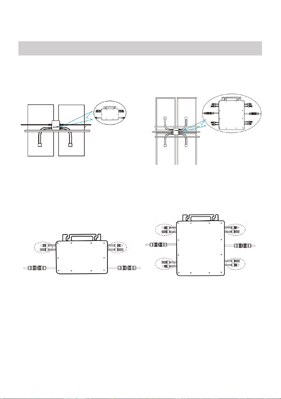
- 17 -
37. Het installatieproces van het bevestigen van de omvormer aan de
PV-beugel met montage
schroeven is als volgt:
GT-600/800 GT-1200
38. Sluit de DC van de PV aan op de omvormer en let op het onderscheid
tussen positief en negatief, zoals hieronder weergegeven:
GT-600/800 GT-1200
39. Open de waterdichte afdekking aan de AC-uitgangszijde van de
micro-omvormer,
en sluit het vervolgens aan op de AC. Als volgt:
INSTRUCTIONS FOR INSTALLATION WIRING
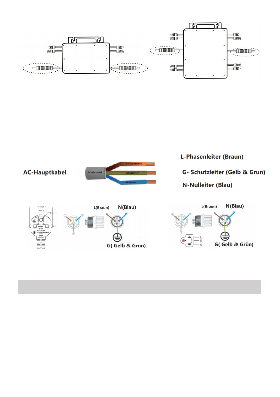
- 18 -
GT-600/800 GT-1200
40. Herhaal stap 1 tot en met 3 om de installatie van de micro-omvormer te
voltooien.
41. Sluit meerdere omvormers aan via AC-uitgangskabels.
42. De AC-hoofdkabel is aangesloten op het elektriciteitsnet.
AC230V 50Hz AC110V 60Hz
SCHEMATIC DIAGRAM OF THE COMPLETION OF THE INSTALLATION
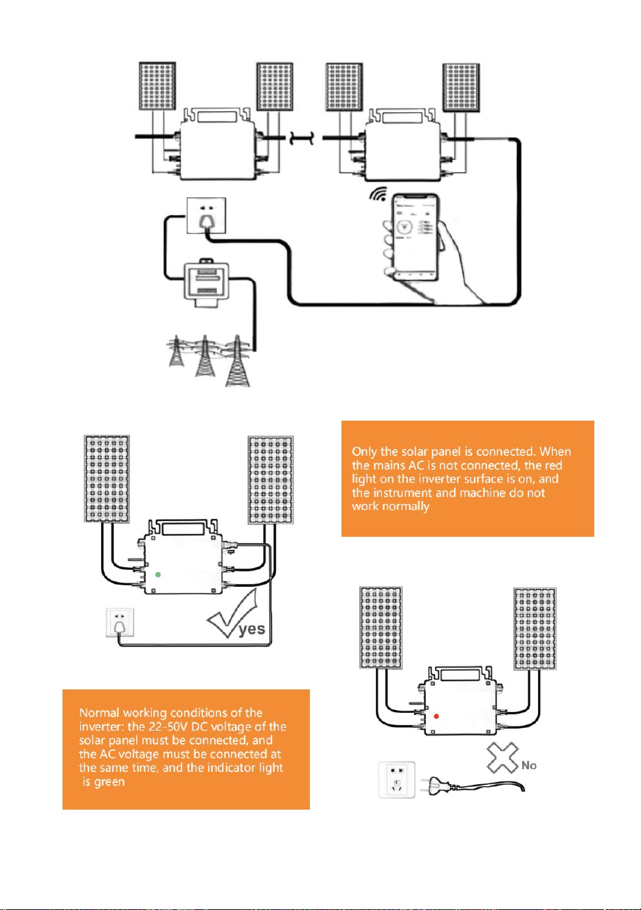
- 19 -
GT-600/800
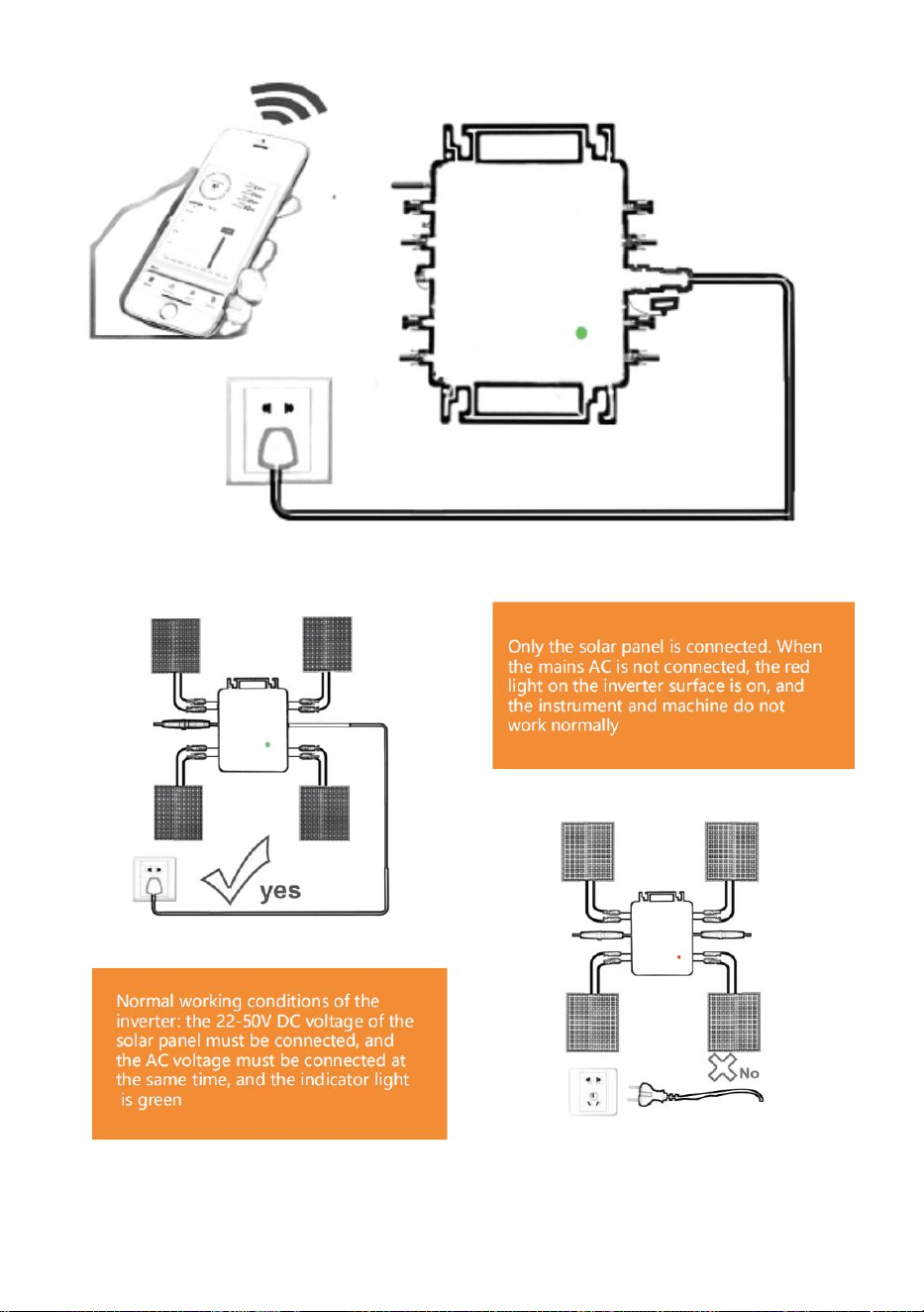
- 20 -
GT-1200
Opmerking:

- 21 -
Wanneer de omvormer voor de eerste keer wordt gekocht en aangesloten op
de
mobiele telefoon voor monitoring, het is alleen nodig om de netspanning
aan te zetten, het blauwe lampje ernaast knippert, en de omvormer kan
worden aangesloten via WIFI of Bluetooth-koppeling. Wanneer de omvormer
kan worden bediend via de mobiele telefoon, wordt aangegeven dat de
verbinding normaal is.

- 22 -
67. WAT TE DOEN als de Smart-App de micro-omvormer niet kan vinden
toegevoegd?
Controleer de volgende punten:
Controleer of de WiFi-statusindicator van de micro-omvormer in de
status 'Blauw knipperend' staat .
Controleer of de Bluetooth-functie van uw smart device is ingeschakeld .
Controleer of het signaal van het draadloze netwerk goed is.
Als dit allemaal het geval is en de omvormer nog steeds niet wordt
gevonden, druk dan langer dan 5 seconden op de rode resetknop om reset.
Nadat het WiFi-indicatielampje weer blauw knippert, gebruikt u de "Smart
Life"-app om het netwerk opnieuw te configureren.
68. WAT MOET IK DOEN als ik meerdere micro-omvormers moet
configureren?
Installeer alle micro-omvormers op de juiste manier en zorg ervoor dat
ze normaal werken om stroom te genereren. werken volgens de
configuratie en met behulp van stappen. De app kan alle omvormers
zoeken die op één moment moeten worden toegevoegd tijd en configureer
ze in één keer.
69. WAT MOET IK DOEN als de SSID van mijn WiFi-netwerk of het
wachtwoord is gewijzigd?
Configureer de omvormer opnieuw volgens de configuratie- en
gebruiksstappen.
70. WAT TE DOEN als de wifi-statusindicator van de omvormer uitgaat, maar
de
apparaat weergegeven op de app is niet online?
Dit betekent dat u verbinding kunt maken met het draadloze
netwerkapparaat, maar niet met de cloud. server. Dit betekent dat uw
draadloze netwerkapparaat geen verbinding kan maken met internet. Zorg
ervoor dat uw Het internet werkt naar behoren.

- 23 -
71. De installatieplaats van de omvormer is tijdelijk niet voorzien van
een router en er is geen WiFi-signaal ?
Hoe verbindt de app de omvormer en hoe detecteert deze of de
omvormer goed werkt?
U kunt een inactieve smartphone gebruiken om de wifi-hotspot voor
het delen van mobiele telefoonsignalen te openen voor verbinding en
configureer de netwerkverbinding opnieuw nadat u de router hebt
geïnstalleerd.
72. Er zijn meerdere WiFi-signalen in de buurt. Kunnen we
verschillende WiFi-signalen verbinden?
Nee, de WiFi-verbinding van de micro-omvormer en de smartphone
moet consistent zijn voordat het netwerk kan worden geconfigureerd.
73. Kan App de micro-omvormer op verschillende plaatsen
configureren? Kan ik gegevens op verschillende plaatsen bekijken?
U kunt de micro-omvormer niet op verschillende plaatsen configureren,
maar u kunt wel gegevens op verschillende plaatsen bekijken. De
omvormer uploadt de meest recente statusgegevens elke 3-5 minuten
naar de cloudserver.
74. Nadat is gecontroleerd of er geen probleem is, kan de app de
micro-omvormer nog steeds niet vinden.
Houd de rode knop van de omvormer langer dan 5 seconden
ingedrukt om de omvormer te resetten.
Nadat de WiFi-indicator opnieuw knippert, gebruikt u de app om het
netwerk opnieuw te configureren.
75. WAT MOET IK DOEN als ik dezelfde omvormer op twee of meer
slimme apparaten wil monitoren?
U kunt de omvormer delen met een andere telefoon met behulp van de
functie Apparaat delen.

- 24 -
76. Worden app-gegevens opgeslagen?
Ja, App-gegevens worden opgeslagen op een cloudserver. Nadat het
netwerk succesvol is geconfigureerd, kunt u de gegevens op elk gewenst
moment en op elke gewenste plaats bekijken.
77. Kan de omvormer 's nachts geen verbinding maken met de app?
's Nachts genereert het zonnepaneel geen stroom en heeft de
micro-omvormer geen stroomtoevoer. Deze is dan offline en het is dan
onmogelijk om het netwerk opnieuw te configureren.
ACCESSORIES LIST
31.Gebruiksaanwijzing *1
32.Netsnoer aangesloten op het net *1
33.8 mm diameter, 28 mm lange inbusschroef + platte ring + veer
ring+moer *2
34.5 mm diameter, 13 mm lange zeskantschroef + moer *2 (600W/800W)
4 mm diameter, 8 mm lange inbusschroef *1 (1200W)
35.WiFi-antenne *1

- 25 -
Fabrikant: Shanghaimuxinmuyeyouxiangongsi
Adres: Shuangchenglu 803nong11hao1602A-1609shi, baoshanqu,
shanghai 200000 CN.
Geïmporteerd naar AUS: SIHAO PTY LTD, 1 ROKEVA
STREETEASTWOOD NSW 2122 Australië
Geïmporteerd naar de VS: Sanven Technology Ltd., Suite 250, 9166
Anaheim Place, Rancho Cucamonga, CA 91730
REP
EC
E-CrossStu GmbH
Mainzer Landstr.69, 60329 Frankfurt am Main.
REP
UK
YH CONSULTING LIMITED.
C/O YH Consulting Limited Office 147, Centurion House,
London Road, Staines-upon-Thames, Surrey, TW18 4AX


- 27 -
Teknisk Support och e-garanticertifikat
www.vevor.com/support
MICRO INVERTER
MODELL: GT-600/GT-800/GT-1200
We continue to be committed to provide you tools with competitive price.
"Save Half", "Half Price" or any other similar expressions used by us only represents an
estimate of savings you might benefit from buying certain tools with us compared to the major
top brands and does not necessarily mean to cover all categories of tools offered by us. You
are kindly reminded to verify carefully when you are placing an order with us if you are
actually saving half in comparison with the top major brands.

- 1 -
MODELL: GT-600/GT-800/GT-1200
GT-600/GT-800 GT-1200
Have product questions? Need technical support? Please feel free to
contact us:
Technical Support and E-Warranty Certificate
www.vevor.com/support
NEED HELP? CONTACT US!
This is the original instruction, please read all manual instructions
carefully before operating. VEVOR reserves a clear interpretation of our
user manual. The appearance of the product shall be subject to the
product you received. Please forgive us that we won't inform you again if
there are any technology or software updates on our product.
MICRO INVERTER
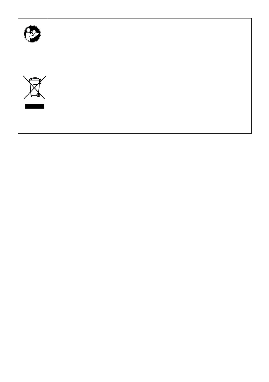
- 2 -
Varning - För att minska risken för skada måste användaren
läsa instruktionerna noggrant.
Denna produkt omfattas av bestämmelserna i det europeiska
direktivet 2012/19/EC. Symbolen som visar en soptunna korsad
anger att produkten kräver separat sophämtning i EU. Detta
gäller för produkten och alla tillbehör märkta med denna
symbol. Produkter märkta som sådana får inte slängas
tillsammans med vanligt hushållsavfall, utan måste lämnas till
en insamlingsplats för återvinning av elektriska och elektroniska
apparater
VARNING: RISK FÖR ELEKTRISK STÖT
Produkten används i kombination med en permanent energikälla (batteri).
Även om utrustningen är avstängd är det farligt
elektrisk spänning kan uppstå vid ingångs- och/eller utgångsterminalerna.
Stäng alltid av strömmen och koppla ur batteriet innan
utföra underhåll.
Produkten innehåller inga interna delar som användaren kan serva. Ta inte
bort frontpanelen och sätt inte produkten i drift om inte alla paneler är
monterade. Allt underhåll ska utföras av kvalificerad personal.
Använd aldrig produkten på platser där gas- eller dammexplosioner kan
inträffa. Se specifikationer som tillhandahålls av tillverkaren av batteri för
att säkerställa att batteriet är lämpligt för användning med denna produkt.
Batteritillverkarens säkerhetsinstruktioner ska alltid vara det observerade.
VARNING: Lyft inte tunga föremål utan hjälp.
Installation
Läs installationsinstruktionerna innan du påbörjar installationen.
Denna produkt är en säkerhetsklass I-enhet (levereras med en
jordterminal av säkerhetsskäl). Dess AC-ingångs- och/eller
utgångsterminaler måste förses med avbrottsfri jordning av säkerhetsskäl.
En extra jordpunkt finns på utsidan av produkten. Om det kan antas att
jordningsskyddet är skadat bör produkten tas ur drift och förhindras från att

- 3 -
oavsiktligt sättas i drift igen; kontakta kvalificerad underhållspersonal.
Se till att anslutningskablarna är försedda med säkringar och brytare. Byt
aldrig ut en skyddsanordning mot en komponent av en
annan typ. Se manualen för rätt del.
Kontrollera innan du slår på enheten om den tillgängliga spänningskällan
överensstämmer med produktens konfigurationsinställningar som beskrivs
i manualen.
Se till att utrustningen används under korrekta driftsförhållanden. Använd
den aldrig i en våt eller dammig miljö.
Se till att det alltid finns tillräckligt med fritt utrymme runt produkten för
ventilation och att ventilationsöppningarna inte är blockerade.
Installera produkten i en värmetät miljö. Se därför till att det inte finns
kemikalier, plastdelar, gardiner eller andra textilier etc.
i omedelbar närhet av utrustningen.
Transport och förvaring
Vid förvaring eller transport av produkten, se till att nät- och batterikablarna
är bortkopplade.
Inget ansvar kan tas för transportskador om utrustningen inte transporteras
i originalförpackningen.
Förvara produkten i en torr miljö; lagringstemperaturen bör variera från
–40°C till 65 ° C.
Se batteritillverkarens manual för information om transport, förvaring,
laddning, laddning och kassering av batteriet.
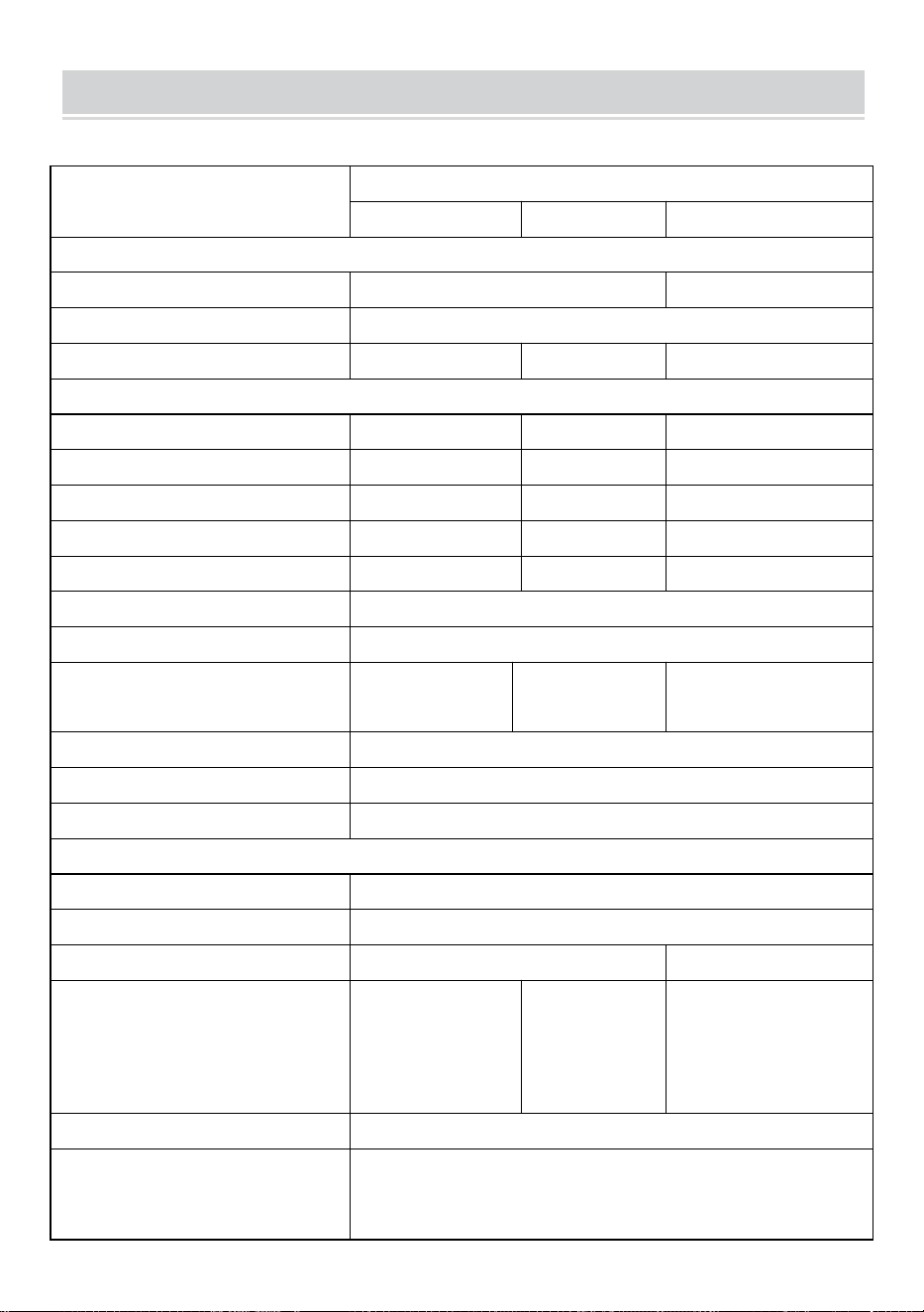
- 4 -
SPECIFICATIONS
Du är välkommen att välja våra mikronätanslutna solinverterprodukter .
Specifikationsdata
Modell
GT-600
GT-800
GT-1200
Indata (DC, PV)
Antal ingångs MC4-kontakt
2 set
4 set
Driftspänningsområde
DC18V-50V
Maximal ingångsström
12A*2
14A*2
16A*2
Utdata (AC)
Enfas nättyp
AC230V
AC230V
AC 110V eller AC 230V
Maximal uteffekt
600W
800W
1200W
Nominell utström
2,6 A
3,5 A
10,9A eller 5,2A
Nominell utspänning
AC230V
AC230V
AC 110V eller AC 230V
Utgångsfrekvensområde
50 Hz
50 Hz
60 Hz eller 50 Hz
Effektfaktor
≥0,99 %
Total harmonisk distorsion
THD <5 %
Maximalt antal enheter per filial
@230VAC: 4 enheter
@230VAC: 3
enheter
@ 110 VAC: 2 enheter Eller @ 230
VAC: 3 enheter
Högsta effektivitet
95 %
Nominell MPPT-effektivitet
99,5 %
Nattströmförbrukning
≤1W
Mekaniska data
Driftsomgivningstemperaturintervall
-40℃ till +65℃
Förvaringstemperaturintervall
-40°C till +85C
Mått (B*H *D)
305 * 186 * 44 mm
490 * 254 * 50 mm
Vattentät klass
IP67
IP65/IP67
(Se
informationen
på produktens
namnskylt)
IP67
Kommunikation
WIFI (molnövervakning)
Skyddsfunktioner
Isolerat öskydd, spänningsskydd
Frekvensskydd
Temperaturskydd, strömskydd, etc.
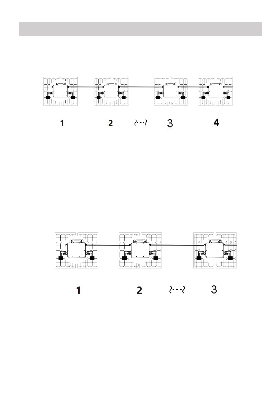
- 5 -
INSTALLATION SCHEMATIC
Enfas parallell monteringsmetod av mikro växelriktare
GT-600
22. @Enfas 230V nät Max 4 enheter 600W Micro växelriktare per gren.
23. Den maximala DC-ingången för varje växelriktare är 600W (PV-modulens
maximala effekt
effekt är 2x300W) .
24. VOC för PV-moduler bör inte vara större än den maximala
DC-ingångsspänningen
av Micro växelriktare .
GT-800
22. @Enfas 230V nät Max 3 enheter 8 00W Micro växelriktare per gren.
23. Den maximala DC-ingången för varje växelriktare är 8 00W (PV-modulens
maxeffekt
effekt är 2x 4 00W) .
24. VOC för PV-moduler bör inte vara större än den maximala
DC-ingångsspänningen
av Micro växelriktare .
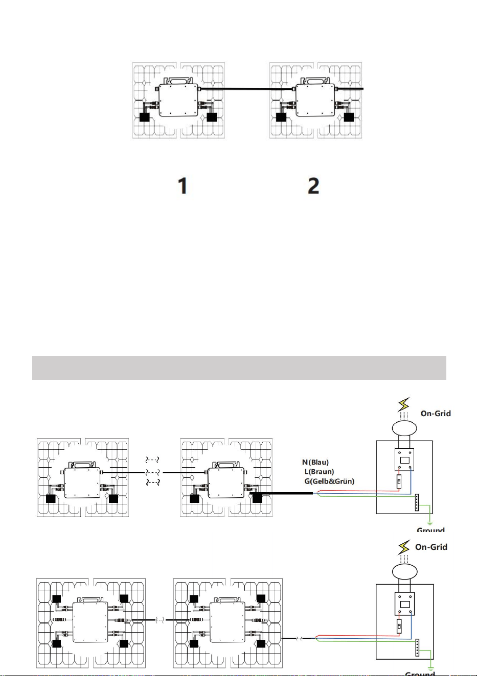
- 6 -
GT-1200
22. @Enfas 110 V-nät Max 2 enheter eller @Enfas 230V nät
Max 3 enheter 12 00W Micro växelriktare per gren.
23. Den maximala DC-ingången för varje växelriktare är 12 00W (PV-modulens
maximala uteffekt
effekt är 2x 6 00W) .
24. VOC för PV-moduler bör inte vara större än den maximala
DC-ingångsspänningen
av Micro växelriktare .
WIRING SCHEMATIC
Enfasig anslutningsmetod för mikroväxelriktare
GT-600/GT-800
GT-1200
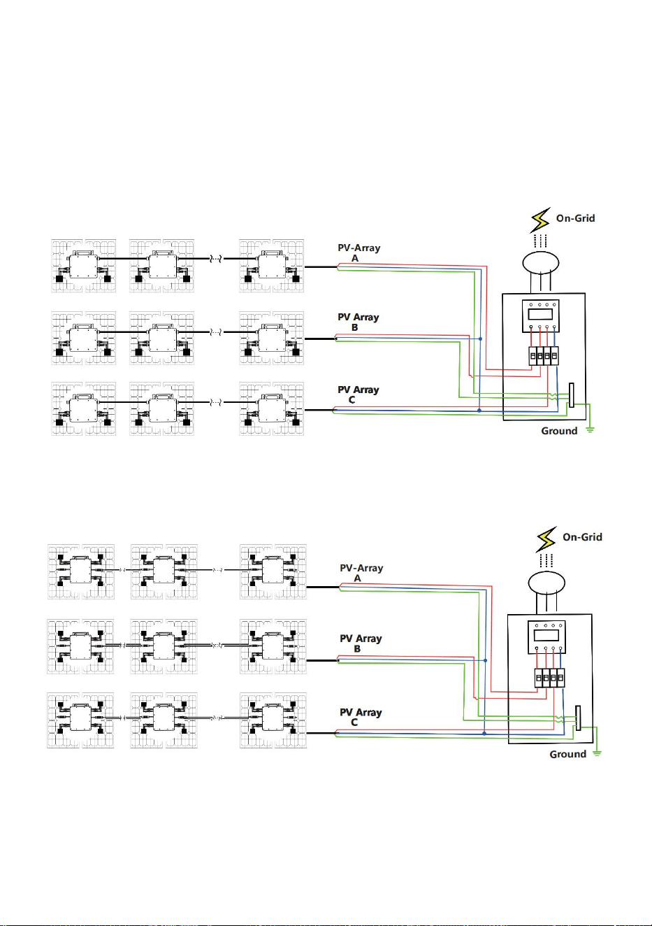
- 7 -
Trefasig anslutningsmetod för mikroväxelriktare
GT-600/GT-800
GT-1200
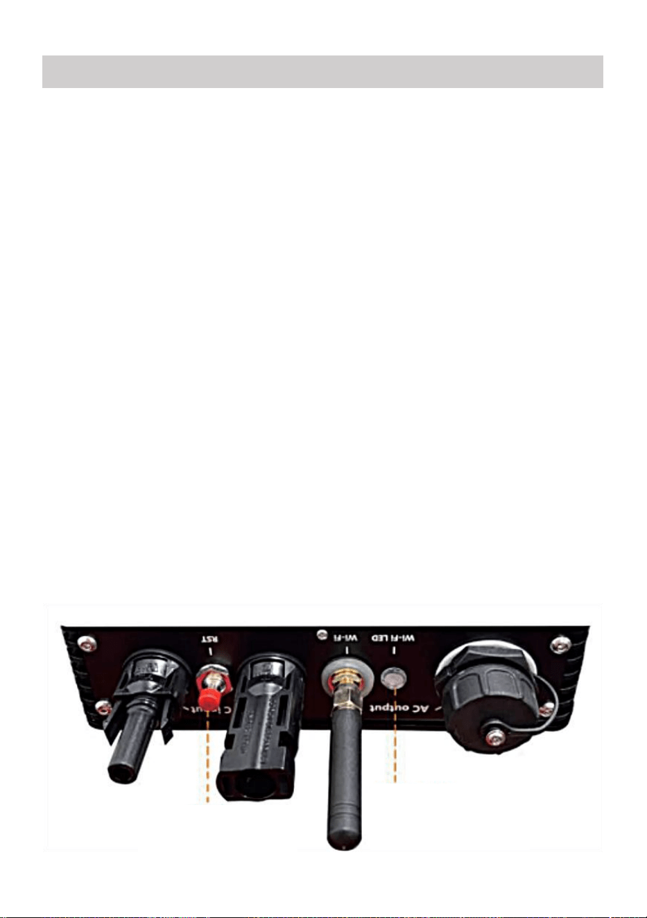
- 8 -
43. Försiktighetsåtgärder
Observera att det finns risk för elektriska stötar vid anslutning av
mikro-invertern!
Mikro-invertern värms upp under drift! Skydda dig själv
följaktligen från brännskador !
Innan du konfigurerar WiFi-molnövervakning, vänligen installera
mikroväxelriktaren korrekt och få det att fungera normalt .
Som mart-enhet (smarttelefon eller surfplatta) med Bluetooth-funktion
och Android eller ett system och en trådlös nätverksenhet, t.ex. trådlös
router som kan tillhandahålla WiFi och internettjänster måste vara
tillgänglig .
För att konfigurera WLAN-molnövervakning, slå först på
Bluetooth-funktionen på den smarta enheten.
Se till att din smarta enhet använder samma WiFi-nätverk som
mikroväxelriktaren som ska konfigureras och att den kan ansluta till
trådlösa nätverksenheter och komma åt internet på samma plats som
mikroväxelriktaren .
Se till att avståndet mellan den trådlösa nätverksenheten och
mikroväxelriktaren inte överstiger 20 m och att det inte finns några eller
få hinder.
44. Hårdvarubeskrivning
MICRO INVERTER WIFI CLOUD MONITORING
WIFI
Set/Reset Button
WIFI Status
LED Indicator
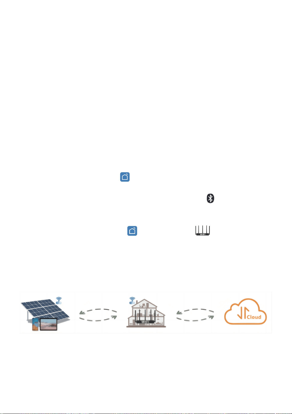
- 9 -
45. WIFI Status LED
Det blå ljuset blinkar efter alltid på = WiFi molnövervakningsmodulen
väntar på konfiguration.
Det blå ljuset släcks efter alltid på = WiFi-molnövervakningsmodulen
startar och går in i normalt arbetsläge.
Den blå lampan blinkar = nätverket är inte konfigurerat eller nätverket
kan inte ansluta till den trådlösa nätverksenheten, eller så har
mikroväxelriktaren raderats i molnet.
Inget ljus = WiFi-molnövervakning fungerar normalt .
46. Förberedelse före konfiguration och användning
Installera mikroväxelriktaren korrekt och få den att fungera normalt för
att generera ström.
Ladda ner och installera eller "Smart Life"-appen genom att söka
efter den i motsvarande Android- eller Apple-appbutik.
Slå på Bluetooth-funktionen på din smarta enhet .
Kontrollera att din trådlösa nätverksenhet (som trådlös router) fungerar
korrekt och är ansluten till Internet .
Använd din smarta enhet ( eller "Smart liv" App installerad) vid
installationsplatsen för mikroväxelriktaren för att ansluta till den
trådlösa nätverksenheten. Om du kan komma åt Internet normalt , följ
instruktionerna för konfiguration och användning på nästa sida.

- 10 -
47. Konfigurationssteg för WIFI-molnövervakning .
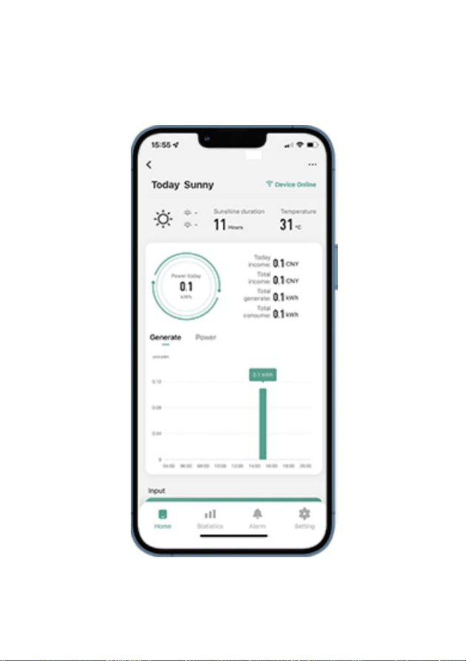
- 11 -
48. Användning av WIFI Cloud Monitoring App .
Ändra enhetsnamn
Klicka på enheten som ska ändras i enhetslistan på startsidan för att gå
till sidan med enhetsinformation (Figur 5).
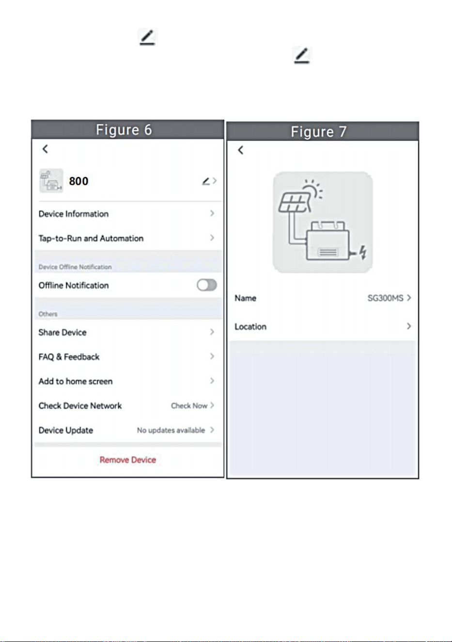
- 12 -
Klicka på knappen i det övre högra hörnet för att komma in på
enhetens inställningssida (Figur 6), fortsätt att klicka på den övre
knappen till sidan med namn och position (Figur 7), klicka på
namnobjektet, ange sedan ett nytt namn och spara det (Figur 8).
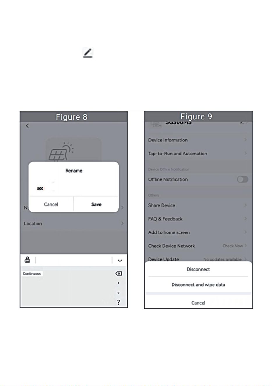
- 13 -
Ta bort enhet
Klicka på enheten som ska raderas i enhetslistan på startsidan för att
ange enhetsinformationen informationssida (Figur 5).
Klicka på knappen i det övre högra hörnet för att gå in på enhetens
inställningssida (Figur 6). Klicka på knappen "Ta bort enhet" nedan
(Figur 9), klicka på knappen "Koppla från" för att ta bort enheten eller
klicka på knappen "Koppla bort och torka data" för att ta bort enheten
och rensa alla data som sparats av enheten i molnet samtidigt.
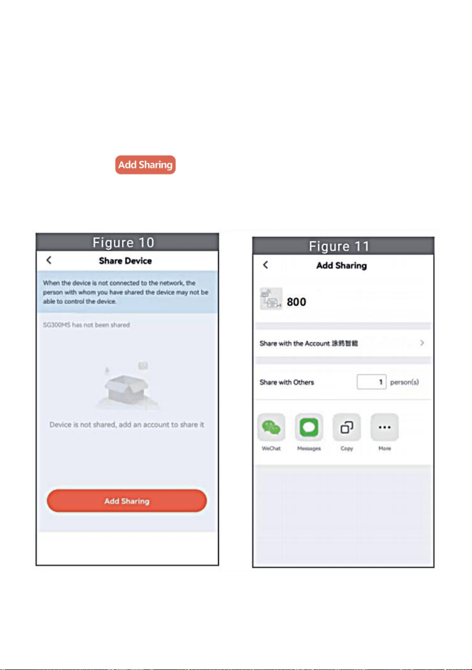
- 14 -
Dela enhet med andra
Klicka på enheten som ska delas i enhetslistan på startsidan för att gå till
sidan med enhetsinformation (Figur 5).
Klicka på knappen uppe till höger för att gå in i sida för
enhetsinställning (Figur 6).
Klicka på "Dela enhet" för att komma in i enheten delningssida (Figur
10) , klicka på knapp för att gå in på sidan " Lägg till delning
" (Figur 11) och välj det bästa delningssättet som du tror att det är mest
bekvämt att dela länken till mikroväxelriktaren.
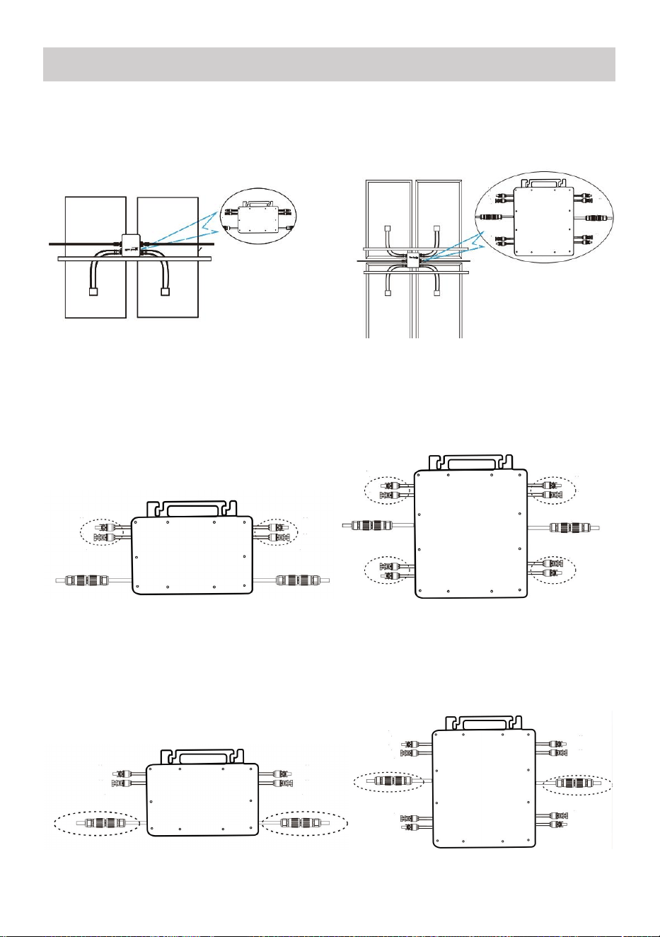
- 15 -
43. Installationsprocessen för att fästa växelriktaren till PV-fästet med
montering
skruvar är som följer:
GT-600/800 GT-1200
44. Anslut DC av PV till växelriktaren, och var uppmärksam på att skilja
mellan positivt och negativt, som visas nedan:
GT-600/800 GT-1200
45. Öppna det vattentäta locket på AC-utgångssidan av mikroväxelriktaren,
och anslut den sedan till AC. Så här:
GT-600/800 GT-1200
INSTRUCTIONS FOR INSTALLATION WIRING
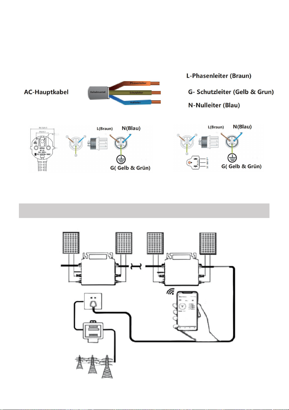
- 16 -
46. Upprepa steg 1 till 3 för att slutföra installationen av mikroväxelriktaren.
47. Anslut flera växelriktare via AC-utgångskablar.
48. AC-huvudkabeln är ansluten till elnätet.
AC230V 50Hz AC110V 60Hz
SCHEMATIC DIAGRAM OF THE COMPLETION OF THE INSTALLATION

- 17 -
GT-600/800

- 18 -
GT-1200
Notera:
När omriktaren köps för första gången och ansluts till
mobiltelefon för övervakning, det är bara nödvändigt att slå på elnätet, det
blå ljuset bredvid blinkar och växelriktaren kan anslutas via WIFI eller
Bluetooth-parning. När växelriktaren kan styras via mobiltelefonen indikeras
att anslutningen är normal.

- 19 -
78. VAD MAN SKA GÖRA när Smart-Appen inte kan hitta den
mikroväxelriktare som ska vara
lagt till?
Kontrollera följande punkter:
Kontrollera om mikroväxelriktarens WiFi-statusindikator är i "Blå
blinkande" tillstånd .
Kontrollera om Bluetooth-funktionen på din smarta enhet är påslagen .
Kontrollera om signalen från det trådlösa nätverket är bra.
Om allt detta är fallet och växelriktaren fortfarande inte hittas, tryck på den
röda återställningsknappen i mer än 5 sekunder för att återställa. När
WiFi-indikatorlampan blinkar blått igen, använd "Smart Life"-appen för att
konfigurera om nätverket.
79. VAD MAN GÖR om jag har flera mikroväxelriktare att konfigurera?
Installera alla mikroväxelriktare ordentligt och få dem att fungera normalt
för att generera ström, och sedan fungerar enligt konfigurationen och med
hjälp av steg. Appen kan söka efter alla växelriktare som ska läggas till
samtidigt tid och konfigurera dem på en gång.
80. VAD MAN GÖR om SSID för mitt WiFi-nätverk eller lösenordet ändras?
Vänligen konfigurera om växelriktaren enligt konfigurationen och med
hjälp av steg.
81. VAD MAN GÖR om växelriktarens WiFi-statusindikator slocknar, men
enhet som visas på är appen inte online?
Det betyder att du kan ansluta till den trådlösa nätverksenheten, men du
kan inte ansluta till molnet server. Det betyder att din trådlösa
nätverksenhet inte kan ansluta till Internet. Se till att din Internet fungerar
som det ska.
82. Installationsplatsen för växelriktaren är tillfälligtvis inte utrustad
med en router och ingen WiFi-signal ?

- 20 -
Hur ansluter appen växelriktaren och känner av om växelriktaren
fungerar som den ska?
Du kan använda en inaktiv smartphone för att öppna WiFi-delning av
mobiltelefonsignals hotspot för anslutning och konfigurera om
nätverksanslutningen efter installation av routern.
83. Det finns flera WiFi-signaler runt omkring. Kan vi ansluta olika
WiFi-signaler?
Nej, WiFi-anslutningen för mikroväxelriktaren och smarttelefonen måste
vara konsekvent innan nätverket kan konfigureras.
84. Kan appen konfigurera mikroväxelriktaren på olika ställen? Kan
jag se data på olika platser?
Du kan inte konfigurera mikroväxelriktaren på olika ställen, men du kan
se data på olika ställen. Växelriktaren laddar upp den senaste statusdatan
till molnservern var 3-5 minut.
85. Efter att ha kontrollerat att det inte är några problem kan appen
fortfarande inte hitta mikroväxelriktaren.
Håll den röda knappen på växelriktaren intryckt i mer än 5 sekunder för
att återställa växelriktaren.
När WiFi-indikatorn blinkar igen, använd appen för att konfigurera om
nätverket.
86. VAD MAN GÖR om jag vill övervaka samma växelriktare på två
eller flera smarta enheter?
Du kan dela växelriktaren med en annan telefon med hjälp av dela
enhetsfunktionen.
87. Kommer appdata att sparas?
Ja, appdata kommer att lagras på molnservern. När nätverket har
konfigurerats kan du se data när som helst och när som helst.
88. Kan växelriktaren inte anslutas till appen på natten?

- 21 -
På natten, eftersom solpanelen inte genererar ström, har
mikroväxelriktaren ingen strömingång, så den går offline och det är
omöjligt att konfigurera om nätverket på natten.
ACCESSORIES LIST
36.Bruksanvisning *1
37.Nätansluten nätsladd *1
38.8 mm diameter, 28 mm lång insexskruv+plattbricka+fjäder
bricka+mutter *2
39.5 mm diameter, 13 mm lång insexskruv+mutter *2(600W/800W)
4 mm diameter, 8 mm lång insexskruv *1(1200W)
40.WiFi-antenn *1

- 22 -
Tillverkare: Shanghaimuxinmuyeyouxiangongsi
Adress: Shuangchenglu 803nong11hao1602A-1609shi, baoshanqu,
shanghai 200000 CN.
Importerad till AUS: SIHAO PTY LTD, 1 ROKEVA STREETEASTWOOD
NSW 2122 Australien
Importerad till USA: Sanven Technology Ltd., Suite 250, 9166 Anaheim
Place, Rancho Cucamonga, CA 91730
REP
EC
E-CrossStu GmbH
Mainzer Landstr.69, 60329 Frankfurt am Main.
REP
UK
YH CONSULTING LIMITED.
C/O YH Consulting Limited Office 147, Centurion House,
London Road, Staines-upon-Thames, Surrey, TW18 4AX

