
Version: V1.00.001
Statement:
THINKCAR
owns the complete intellectual property rights for the software
used by this product. For any reverse engineering or cracking actions against the software,
THINKCAR will block the use of this product and reserve the right to pursue their legal
liabilities.
THINKCAR

www.thinkcar.com
THINKCAR
I
Copyright Information
Copyright © 2020 by THINKCAR TECH CO., LTD(hereinafter referred to as “THINKCAR”). All rights
reserved. No part of this publication may be reproduced, stored in a retrieval system, or transmitted in any
form or by any means, electronic, mechanical, photocopying and recording or otherwise, without the prior
written permission of THINKCAR. The information contained herein is designed only for the use of this
unit. THINKCAR is not responsible for any use of this information as applied to other units.
Neither THINKCAR nor its aliates shall be liable to the purchaser of this unit or third parties for damages,
losses, costs, or expenses incurred by purchaser or third parties as a result of: Accident, misuse, or abuse
of this unit, or unauthorized modications, repairs, or alterations to this unit, or failure to strictly comply with
THINKCAR operating and maintenance instructions. THINKCAR shall not be liable for any damages or
problems arising from the use of any options or any consumable products other than those designated as
Original THINKCAR Products or THINKCAR Approved Products.
Formal statement: The names of other products mentioned in this manual are intended to explain how to
use this equipment, and the registered trademark ownership still belongs to the original company.
This equipment is designed for professional technicians or maintenance personnel.
Trademark
THINKCAR is a registered trademark of THINKCAR TECH CO., LTD in China and other overseas
countries. All other THINKCAR trademarks, service marks, domain names, logos, and company names
referred to in this manual are either trademarks, registered trademarks, service marks, domain names,
logos, company names of or are otherwise the property of THINKCAR or its aliates. In countries where
any of the THINKCAR trademarks, service marks, domain names, logos and company names are not
registered, THINKCAR claims other rights associated with unregistered trademarks, service marks,
domain names, logos, and company names. Other products or company names referred to in this manual
may be trademarks of their respective owners. You may not use any trademark, service mark, domain
name, logo, or company name of THINKTOOL or any third party without permission from the owner of the
applicable trademark, service mark, domain name, logo, or company name.
You may contact THINKCAR TECH INC by visiting the website at www.thinkcar.com, or writing to
THINKCAR TECH CO., LTD., Room 2606, Block#4, Tian'an Cloud Park, Bantian, Longgang District,
Shenzhen, China, to request written permission to use Materials on this manual for purposes or for all
other questions relating to this manual.
Safety Precautions and Warnings
To avoid personal injury, property loss, or accidental damage to the product, read all of the information in
this section before using the product.
Handle equipment carefully
Do not drop, bend, or puncture the tool, or insert extra objects into or place heavy objects on the device.
The vulnerable components inside may be damaged.
Do not disassemble or modify the equipment
The device is a sealed device with no user-serviceable parts inside. All internal repairs must be performed

www.thinkcar.com
THINKCAR
II
by an authorized maintenance organization or qualied technician. Attempts to disassemble or modify the
device will void the warranty.
Do not try to replace the internal battery
The internal rechargeable lithium battery must be replaced by an authorized maintenance organization or
qualied technician. Contact the dealer for factory replacement.
Adapter information
Avoid immersing the device in water or placing it in a location where it may absorb moisture or other liquids.
During normal use, the charging device may become hot. Please ensure that there is good ventilation
while charging device.
If any of the following situation occurs, please unplug the charging device:
• The charging device is exposed to rain, liquid or in an environment with excessive overlap.
• The charging device showed physical damage.
• The charging device is under cleaning.
Data and Software Protection
Do not delete unknown les or change the names of les or directories created by others, otherwise the
device software may not run.
!
Note: Access to network resources makes the device vulnerable to computer viruses, hackers, spyware, and
other malicious behaviors, and may damage the device, software, or data. To make ensure that you are using
rewalls, anti-virus software and anti-spyware software to provide adequate protection for your computer and
keep these software up to date.
Precautions on Using this tool
• Make sure the ignition switch should be in the OFF position when plugging and unplugging the
diagnostic connector.
• Keep the connector in the storage box on the back of the main unit, when the vehicle diagnosis is nished.
• Gently press the diagnostic connector to pop up the diagnostic connector. Do not pull or use sharp
objects to pry the diagnostic connector.
Precautions on Operating Vehicle’s ECU
• Do not disconnect battery or any wiring cables in the vehicle when the ignition switch is on, as this could
avoid damage to the sensors or the ECU.
• Do not place any magnetic objects near the ECU. Disconnect the power supply to the ECU before
performing any welding operations on the vehicle.
• Be extremely careful when performing any operations near the ECU or sensors. Ground yourself when
you disassemble PROM, otherwise ECU and sensors can be damaged by static electricity.
• When reconnecting the ECU harness connector, make sure it is attached rmly, otherwise electronic
elements, such as ICs inside the ECU, can be damaged.

www.thinkcar.com
THINKCAR
III
Content
1. Quick Start Manual ............................................................................................................ 1
1.1 Initial Use ............................................................................................................................................. 1
1.1.1 Turn on the Machine ................................................................................................................... 1
1.1.2 Language Setting ........................................................................................................................ 1
1.1.3 Connect Wi-Fi ............................................................................................................................. 1
1.1.4 Choose Time Zone ..................................................................................................................... 2
1.1.5 User Agreement .......................................................................................................................... 2
1.1.6 Create an Account ...................................................................................................................... 3
1.1.7 VCI Activation ............................................................................................................................. 3
1.2 Diagnosis Flowchart ............................................................................................................................ 4
1.3 Function Menu ..................................................................................................................................... 4
1.4 Charging .............................................................................................................................................. 5
1.5 Battery ................................................................................................................................................. 5
1.6 VCI Connections.................................................................................................................................. 5
2. Introduction ........................................................................................................................6
2.1 Product Prole ..................................................................................................................................... 6
2.2 Components & Controls ...................................................................................................................... 6
2.3 Function Modules (Optional) ............................................................................................................... 8
2.4 THINKLINK Video Remote diagnosis Device ...................................................................................... 9
2.5 Parameters .......................................................................................................................................... 9
3. Begin to Use.....................................................................................................................10
3.1 Intelligent Diagnosis .......................................................................................................................... 10
3.2 Local Diagnosis ................................................................................................................................. 10
3.2.1 Manual Diagnosis ......................................................................................................................11
3.2.2 System Selection ...................................................................................................................... 13
3.2.3 Function Selection .................................................................................................................... 13
3.3 Maintenance ...................................................................................................................................... 17
3.3.1 Oil Reset ................................................................................................................................... 17
3.3.2 Elec. Throttle Adaption .............................................................................................................. 17
3.3.3 Steering Angle Reset ................................................................................................................ 18
3.3.4 Battery Matching ....................................................................................................................... 18
3.3.5 ABS Bleeding ............................................................................................................................ 18
3.3.6 Break-pad Reset ....................................................................................................................... 18
3.3.7 DPF Regeneration .................................................................................................................... 19
3.3.8 Gear Learning ........................................................................................................................... 19
3.3.9 IMMO Service ........................................................................................................................... 19
3.3.10 Injector Coding ........................................................................................................................ 19
3.3.11 TPMS Reset ............................................................................................................................ 19
3.3.12 Suspension Matching ............................................................................................................. 20
3.3.13 AFS Reset ............................................................................................................................... 20
3.3.14 A/T Learning ........................................................................................................................... 20

www.thinkcar.com
THINKCAR
IV
3.3.15 Sunroof Initialization ............................................................................................................... 20
3.3.16 EGR Adaption ......................................................................................................................... 20
3.3.17 ODO Reset ............................................................................................................................. 20
3.3.18 Airbag Reset ........................................................................................................................... 20
3.3.19 Transport Mode ....................................................................................................................... 20
3.3.20 A/F Reset ................................................................................................................................ 21
3.3.21 Stop/Start Reset ..................................................................................................................... 21
3.3.22 NOx Sensor Reset .................................................................................................................. 21
3.3.23 AdBlue Reset (Diesel Engine Exhaust Gas Filter) .................................................................. 21
3.3.24 Seat Calibration ...................................................................................................................... 21
3.3.25 Coolant Bleeding .................................................................................................................... 21
3.3.26 Tyre Reset .............................................................................................................................. 21
3.3.27 Windows Calibration ............................................................................................................... 21
3.3.28 Language Change .................................................................................................................. 21
3.4 TPMS Diagnostics ............................................................................................................................. 21
3.5 Diagnostic Feedback ......................................................................................................................... 22
3.6 Repair Info ......................................................................................................................................... 23
3.6.1 Fault Code Enquiry ................................................................................................................... 23
3.6.2 Vehicle Coverage Enquiry ........................................................................................................ 23
3.6.3 Learning Course ....................................................................................................................... 23
3.7 ThinkFile ............................................................................................................................................ 23
3.8 ThinkStore ......................................................................................................................................... 24
3.9 ADAS (Optional) ................................................................................................................................ 24
4. Software Update ..............................................................................................................25
4.1 Upgrade all Software ......................................................................................................................... 25
5. Set Up ...............................................................................................................................25
5.1 VCI..................................................................................................................................................... 25
5.2 VCI Management............................................................................................................................... 26
5.3 Activate VCI ....................................................................................................................................... 26
5.4 Fix VCI Firmware/system .................................................................................................................. 26
5.5 Data Stream Sample ......................................................................................................................... 26
5.6 My Order............................................................................................................................................ 26
5.7 Prole ................................................................................................................................................ 26
5.8 Change Password ............................................................................................................................ 26
5.9 Wi-Fi Settings .................................................................................................................................... 26
5.10 Diagnostic Software Clear ............................................................................................................... 26
5.11 Business Information ....................................................................................................................... 27
5.12 Customer Management ................................................................................................................... 27
5.13 Photo Album .................................................................................................................................... 27
5.14 Screen Recorder ............................................................................................................................. 27
5.15 Settings............................................................................................................................................ 27
6.FAQ ....................................................................................................................................27
www.thinkcar.com
THINKCAR
1
1. Quick Start Manual
1.1 Initial Use
The following settings should be made when you initially use the tool.
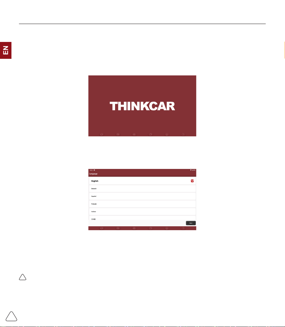
1.1.1 Turn on the Machine
After pressing the power button, images will be shown on the screen as follows.
1.1.2 Language Setting
Select the tool language from the languages listed on the interface.
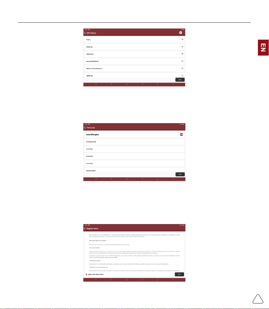
1.1.3 Connect Wi-Fi
The system will automatically search all available Wi-Fi networks for you to choose. If the chosen network
is open, you can connect it directly; If the chosen network is encrypted, you must enter the correct
password. Then you can connect Wi-Fi after clicking “connect”.
!
Tips: Wi-Fi must be set. If no Wi-Fi network is available nearby, you can enable "Portable Mobile Hotspot".
www.thinkcar.com
THINKCAR
2
1.1.4 Choose Time Zone
Select the time zone of your current location, then the system will automatically cogure the time according
to the time zone you selected.
1.1.5 User Agreement
Please read all the terms and conditions of the user agreement carefully. Choose “Agree all the above
terms”, and click the “Agree” button to complete the registration process.
Then the page will jump to the “Congratulations on your successful registration” interface.
www.thinkcar.com
THINKCAR
3
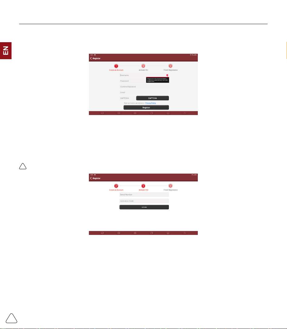
1.1.6 Create an Account
You need to register an account with your e-mail box. If you have owned other products of THINK series,
you can directly log in by using the existing account.
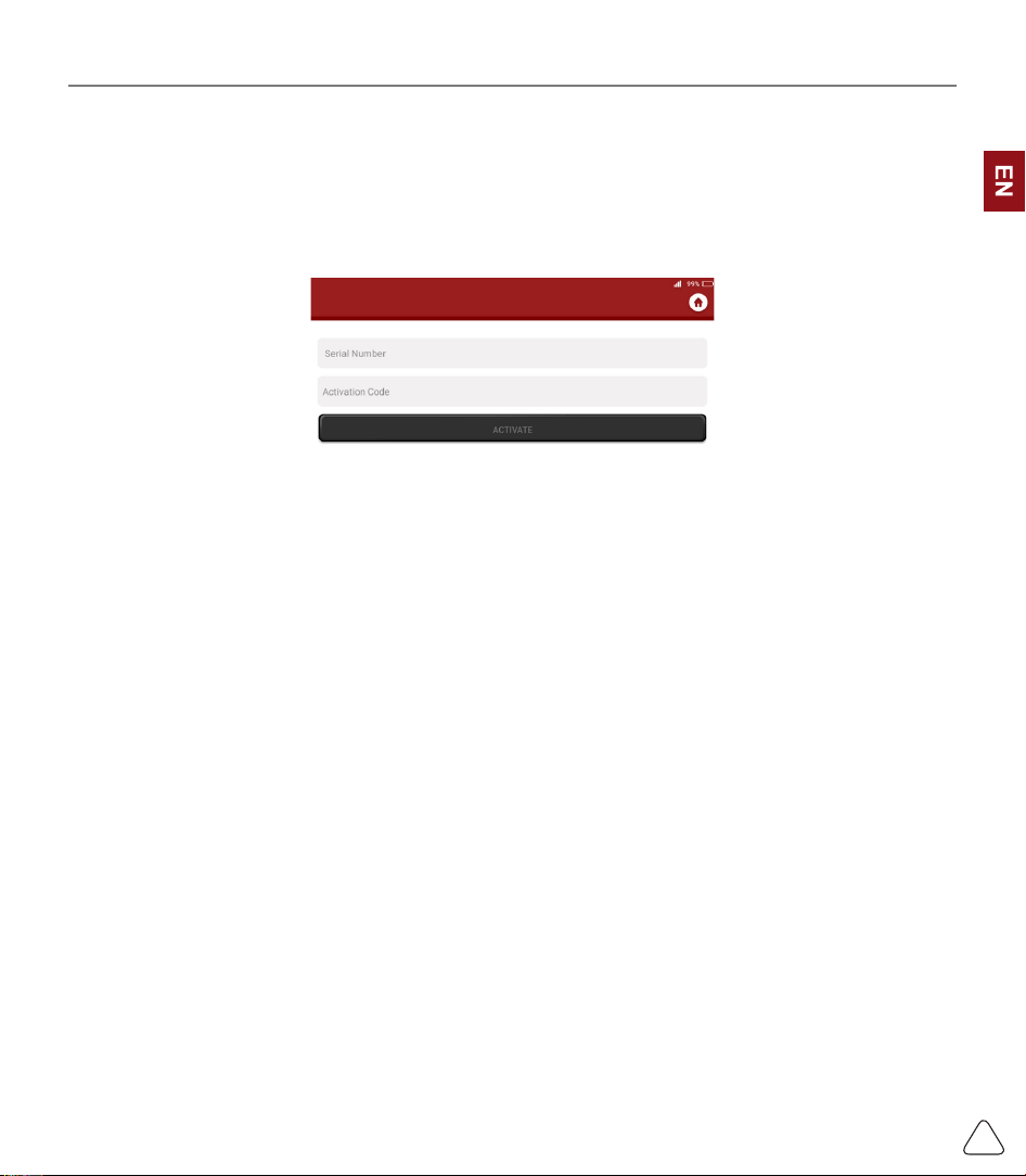
1.1.7 VCI Activation
Input the connector serial number and activation code to activate and bind the diagnostic connector. If you
have not activated it, you can also click "Settings" on the main interface to enter and select "Activate" to
operate.
!
Tips: The activation code is an 8-digit number and is pasted on the "password letter".
www.thinkcar.com
THINKCAR
4
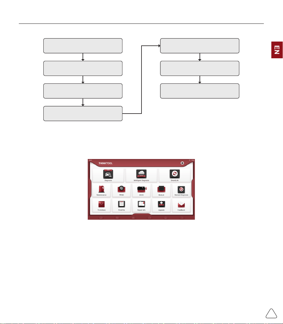
1.2 Diagnosis Flowchart
Register / Create an Account
Connect Diagnostic Connector
Wi-Fi Connection
Activation
Log in Choose Vehicle Type
Choose System
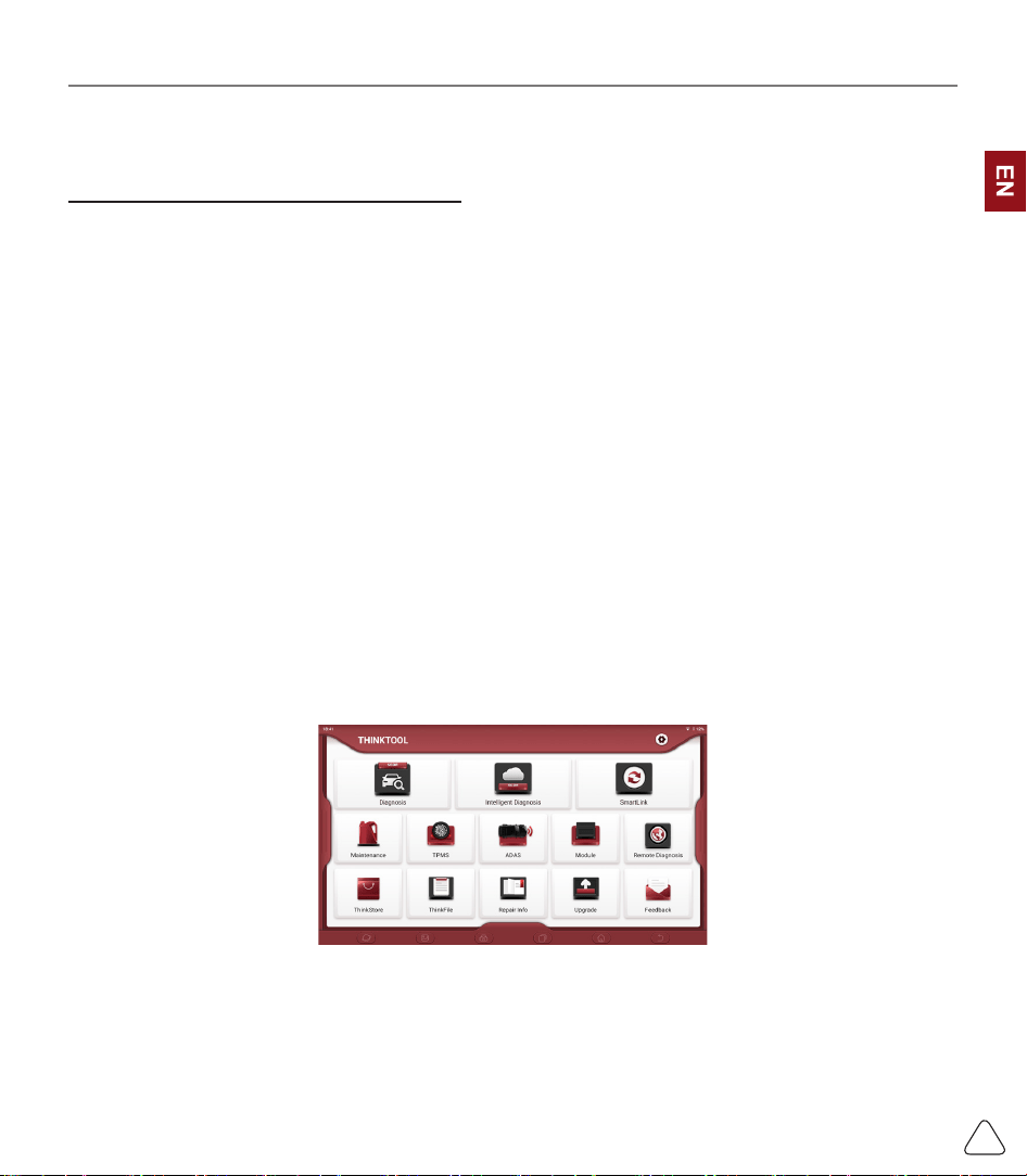
1.3 Function Menu
Power on the main unit, the system will automatically enter into the function menu selection interface:
It mainly includes the following features:
• The main unit and diagnostic connector support Wi-Fi, Bluetooth and wired communication. Wired
communication is superior to Bluetooth connection in terms of transmission rate and anti-interference.
Also wired connection is recommended for online programming function.
• Supports powerful intelligent VIN recognition technology, which is convenient, fast and ecient.
• Heavy Duty Diagnosis (Optional) : Diagnose 24V cars, like trucks, buses, construction vehicles.
• Modular expansion: Support 4 optional modules: videoscope, battery tester, scope box, wireless TPMS
tool.
• It can detect faults in the electronic control systems of most high-, medium-, and low-end vehicles in
Asia, Europe, the United States and China. Powerful diagnostic functions include reading fault codes,
clearing fault codes, reading data streams, action tests, and special functions.
• Maintenance function: matching, coding, programming of most vehicles’ programable modules, and most

www.thinkcar.com
THINKCAR
5
commonly used maintenance and reset functions: Oil Reset, Elec. Throttle Adaption, IMMO Service,
Injector Coding, Break-pad Reset, Steering Angle Reset, ABS Bleeding, AFS Reset, Battery Matching,
A/T Learning, DPF Regeneration, EGR Adaption, TPMS Reset, Sunroof Initialization, Suspension
Matching, Gear Learning, Airbag Reset, ODO Meter Reset, AdBlue Reset, A/F Reset, Coolant Bleeding,
Language Change, NOx Sensor Reset, Seat Calibration, Stop/Start Reset, Transport Mode, Tyre Reset,
Windows Calibration.
• TPMS function: with wireless TPMS tool, TPMS activation, programming and learning functions can be
supported.
• Online one click to update diagnosis software, client and rmware.
• Feedback: In case of any abnormal of software or function during diagnosis, please report to us. Our
professional technian will track and x it shortly.
1.4 Charging
Follow the steps below to charge the main unit:
• Connect the other end to the charging jack on the bottom of the main unit.
• Plug the charger power plug into a power outlet to start charging.
• When the battery status icon displays , the main unit has been charged.
When it displays , the charging process has been completed and you shall disconnect the main unit.
1.5 Battery
• It is normal that the main unit won’t turn on when charging because the battery has not been used for a
long time or it is exhausted. Please turn on the main unit again after charging the battery for a while.
• Please charge the main unit through the charger in the package. Thinkcar Tech takes no responsibility
for damages and losses caused by charging with chargers other than those specied by the company.
• The battery is rechargeable. However, as the battery is a wear part, the standby time of the device will
be shortened after long-time use. Please avoid frequent repeated charging so as to extend battery life.
• The battery charging time varies with temperature and battery status.
• When the battery power is low, the system will pop up a prompt reminding you to connect the charger.
When the battery power is too low, the device will turn o.
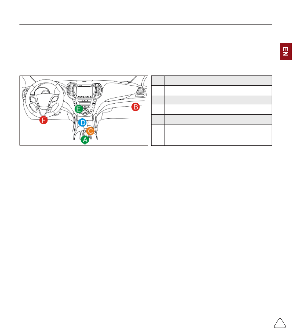
1.6 VCI Connections
Connection steps as below:
(1) Locate vehicle’s DLC socket. Most of the DLC are standard OBDII diagnostic sockets (non-standard
OBDII vehicle diagnostic sockets need to use the corresponding adapter).The DLC is usually located
12 inches from the center of the instrument panel (dash), under or around the driver’s side for most
vehicles. If the DLC cannot be found, refer to the vehicle’s service manual for the location.
(2) For OBDII vehicle, follow the steps described below to proceed.
www.thinkcar.com
THINKCAR
6
a) Use the OBDII extension cable to connect the VCI dongle and DLC socket
(3) For non-OBDII vehicle, If the pin of the DLC is damaged or has insucient power, please follow the
either of the following methods to proceed:
a) Cigarette Lighter cable
b) Battery Clamps Cable
A Opel, Volkswagen, Audi
B Honda
C Volkswagen
D Opel, Volkswagen, Citroen
E Changan
F
Hyundai, Daewoo, Kia, Honda, Toyota, Nissan,Mitsubishi,
Renault, Opel, BMW, Mercedes-Benz, Mazda, Volkswagen,
Audi, GM, Chrysler,Peugeot, Regal, Beijing Jeep, Citroen and
most prevailing models
2. Introduction
2.1 Product Prole
THINKTOOL is a new generation intelligent diagnostic equipment. With advanced technology and stronger
hardware, THINKTOOL is the most powerful diagnostic tool in the market.
THINKTOOL has 13.3’ LED touch screen and 720 nits brightness, as well as robust plastic cover and
perfect industrial design. By Wi-Fi connection, diagnostic speed is more fast.
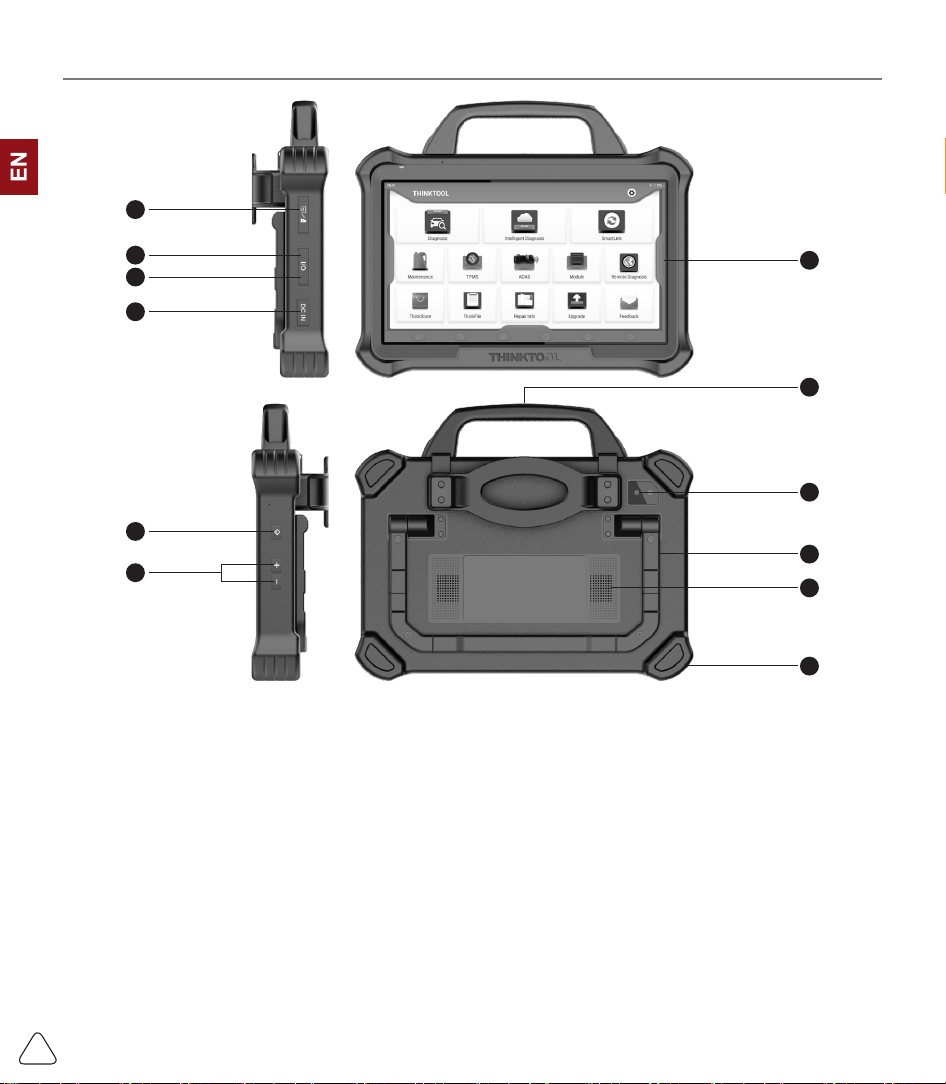
2.2 Components & Controls
www.thinkcar.com
THINKCAR
7
(1)
Screen
(2)
Power/Lock Screen Key
Press the key about 5s to power on the pad. Single click to sleep or awake the pad.
(3)
Type C Port:
connect with computer to transmit the data.
(4)
USB Port:
connect with USB tool or extensive modules.
(5)
DC Port
(6)
Rear Camera
(7)
Speaker
(8)
Volume Icon
(9)
HDMI Interface
(10)
Adjustable Holder:
180° adjustable angle. Support lift, support and normal model.
(11)
Rubber Corner
(12)
Handle
9
4
3
5
2
8
1
6
12
11
7
10
www.thinkcar.com
THINKCAR
8
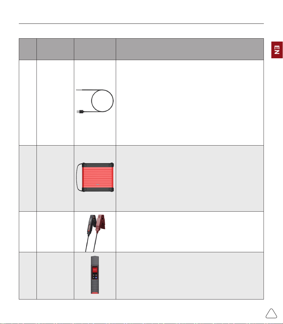
2.3 Function Modules (Optional)
S/N Name Image Description
1
THINK Video
Scope
Super long custom coil pipeline design, flexible bending
with durable materials, suitable for a variety of complex
environments. Multiple uses with 3 kinds of special
connectors (Hook, side view mirror, magnet). Supports 720P
HD image. With 6 auxiliary lights for brighter light, easily
used in dark environment.
Application scenarios: 1. Engine combustion chamber
inspection; 2. Engine internal carbon deposit inspection; 3.
Three-way catalytic inspection; 4. Air-conditioning pipeline
inspection; 5. The corners of the vehicle that are not easy to
detect, such as falling screws, or water leakage, cracks, and
foreign objects…
2
THINK
Scope Box
Equipped with 4 channels 100MHz bandwidth, sampling
rate reaches up to 1GS/ s. Combined with the THINKTOOL
screen to achieve full touch control operation. Specially
developed auto repair and detection special menu and HD
waveform display brings more convenient for usage.
Application scenarios: The THINK Scopebox can accurately
determine the problems of sensors, actuators, control
modules or lines.
3 THINKEASY
With high resolution screen and high precision data, can
diagnose battery information, like battery power, voltage,
internal resistance, lifetime, starting current and so on.
Application: Check the car battery health status, starting
system and charging system.
4
Wireless
TPMS G1
Work with THINKTOOL to complete tire pressure diagnosis
related functions.
Application scenarios: 1. Read tire pressure information such
as pressure, temperature, and battery status; 2. Change the
sensor for programming; 3. Change the position of the tire or
other abnormalities that require sensor learning.
www.thinkcar.com
THINKCAR
9
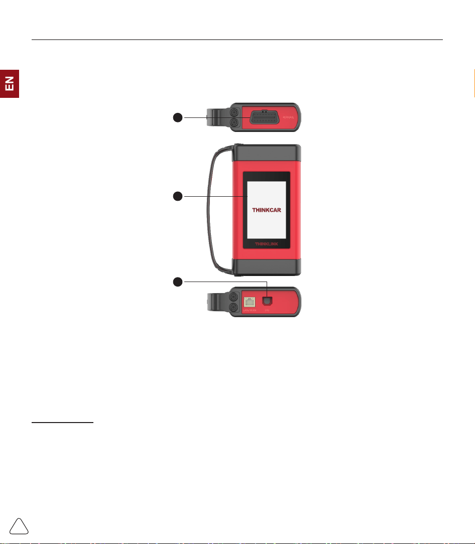
2.4 THINKLINK Video Remote diagnosis Device
1) VCI (Vehicle Communication Interface) is used together with diagnsotic tool.
2) When used as a local J2534 tool, it can be used with the original diagnostic software for vehicle ECU
ashing.
2
3
1
(1)
OBD-16 diagnostic interface
: used to connect with the OBDII extension cord.
(2)
Display
: display working status.
(3)
I/O data transmission port
: used to connect with the diagnosis host/computer and THINKLINK Video
Remote diagnosis Device equipment for wired communication.
2.5 Parameters
Host computer
• Operating System: Android 9.0
• Memory: 8G
• Storage: 256G
• Battery: 9300mAh/7.6V
• Screen: 13.3 inches
• Camera: Rear camera 13.0MP
• Network: Wi-Fi, WLAN 802.11b/g/n
• Bluetooth: Bluetooth 4.2
www.thinkcar.com
THINKCAR
10
• Working Temperature: 32
℉
~122
℉(
0
℃
~ 50
℃)
• Storage Temperature: -4
℉
~140
℉
(-20
℃
~ 60
℃)
THINKLINK Video Remote diagnosis Device
• Memory: 256M
• Storage: 8G
• Screen: 3.97 inches
• Power: ≤6W
• Operating Voltage: 9~36V
• Communication method: Local diagnostic mode: Wi-Fi/USB
• Working Temperature: 14
℉
~122
℉ (1
0
℃
~ 50
℃)
• Storage Temperature: -4
℉
~140
℉
(-20
℃
~ 60
℃)
3. Begin to Use
Diagnostic function, coverage more than 100 car brands, support intelligent diagnosis and traditional
diagnosis, including OBDII full-function diagnosis, full-system diagnosis including: read fault code, clear
fault code, read real-time data stream, special function, actuation test. A diagnosis report can be generated
after the diagnosis.
3.1 Intelligent Diagnosis
Connect the vehicle first, click “Intelligent Diagnosis”on the main interface, the tool will start the smart
diagnosis program and automatically read the vehicle VIN, as shown in below:
If the device failed to access the VIN information, please use “Local Diagnosis”.
3.2 Local Diagnosis
In this mode, user can manually select vehicle models and systems for diagnosis.
www.thinkcar.com
THINKCAR
11
3.2.1 Manual Diagnosis
THINKTOOL also supports step-by-step manual selection of menus for diagnosis.
To use the "DEMO" as an example to introduce how to start the diagnosis as below.
1) Select vehicle type: click on the "demo " icon on the main diagnostic interface to enter.
!
Tips: The diagnosis menu varies with dierent vehicles
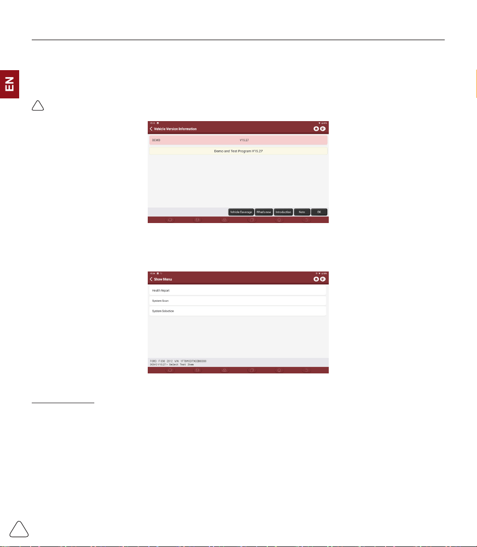
2) Select Diagnostic method: After the connection is successful, the screen will enter the test item selection
interface.
A.Health Report: It enables you to quickly access all the electronic control units of the vehicle and generate
a detailed report about vehicle health. ( This function varies from vehicle to vehicle.)
Click "Health Report", the system will start scanning the ECUs to see if there is fault code and display the
specic results.
www.thinkcar.com
THINKCAR
12
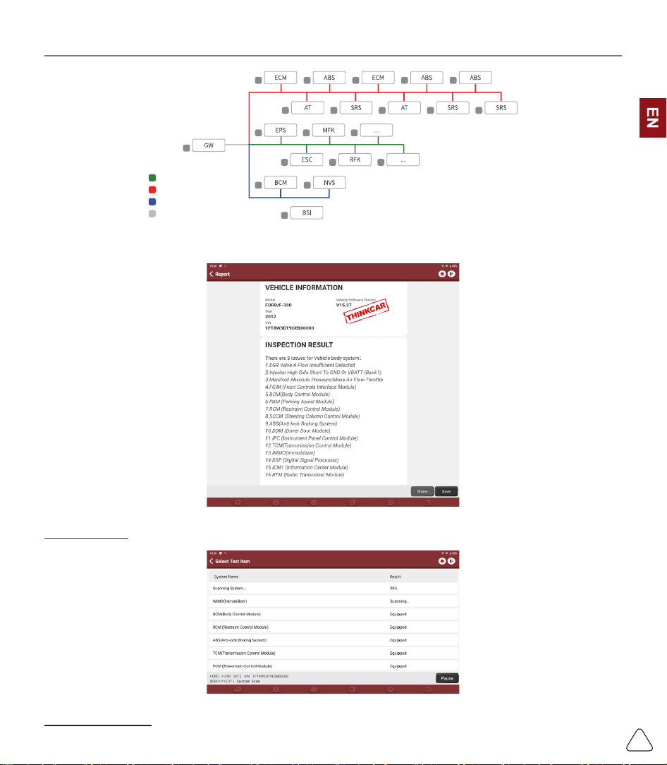
Normal
Abnormal
Not Scanned
Not Equipped
Click "Report" to generate a vehicle health report.
B.System Scan: automatically scan all systems of the vehicle
C.System Selection: manually select the automotive electronic control system.
www.thinkcar.com
THINKCAR
13
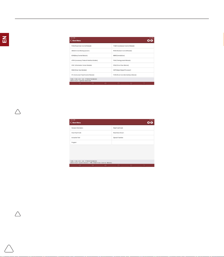
3.2.2 System Selection
Select the system: Click “PCM” (e.g.), and the screen will enter selection interface
3.2.3 Function Selection
Click the function to be tested
!
Tips: The diagnosis menu varies with dierent vehicles
a) Version Information
As shown in the picture, click “Version Information” to read the current version information of the car ECU.
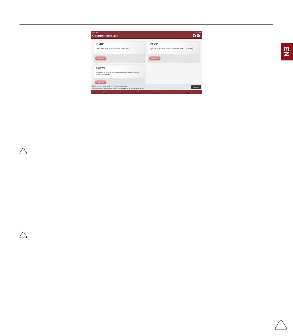
b) Read Fault Code
This function is to read the DTC in the ECU memory, helping maintenance personnel to quickly identify the
cause of the vehicle breakdown.
As shown below, click “Read Fault Code”, and then the screen will display diagnostic results.
!
Tips: Reading the DTC when troubleshooting a vehicle is only a small step in the entire diagnostic process.
Vehicle DTC are for reference only, and parts cannot be replaced directly based on the given DTC denition.
Each DTC has a set of test procedures. The maintenance technician must strictly conform to the operation
instructions and procedures described in the car maintenance manual to confirm the root cause of the
breakdown.
www.thinkcar.com
THINKCAR
14
c) Clear DTC
On the diagnostic function selection screen, tap Clear Fault Code, the system will automatically delete the
currently existing DTCs and display the dialog box of "DTCs Cleared".
!
Note: For general models, please operate strictly according to the normal sequence: read DTC - clear DTC -
test the car - retrieve DTC for verication - repair the car - clear DTC – recheck the car, to conrm that the
DTC no longer appears.
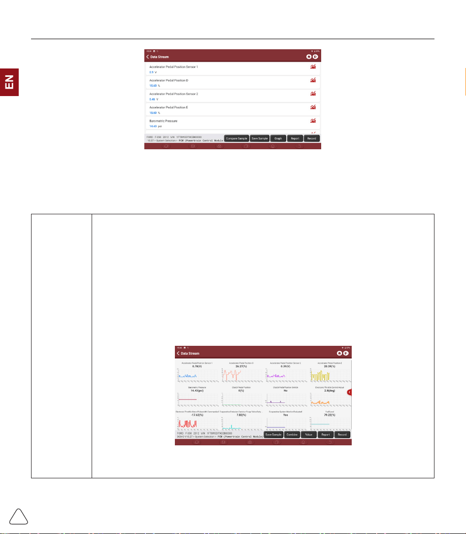
d) Read data stream
This option allows you to you view and capture (record) real-time Live Data of ECU. This data, including
current operating status for parameters and/or sensor information, can provide insight on overall vehicle
performance. It can also be used to guide vehicle repair.
!
Note: If you must drive the vehicle in order to perform a troubleshooting procedure, ALWAYS have a second
person help you. Trying to drive and operate the diagnostic tool at the same time is dangerous, and could cause
a serious trac accident.
www.thinkcar.com
THINKCAR
15
On-screen Buttons:
[Graph]
Displays the parameters of the selected data stream in waveform. On the data stream
waveform page, you can do the following:
[Combine]: Displayed in graph merge status for data comparison.
[Value]: Displayed the parameters in values and shown in list format.
[Customize]: Customize the data stream option to be viewed. Tap the button, a pull-
down list of the data stream items appears on the screen. Select the desired items (max
12 items), and then screen will display the waveforms corresponding to these items
immediately. If need to remove any items, just deselect them.
www.thinkcar.com
THINKCAR
16
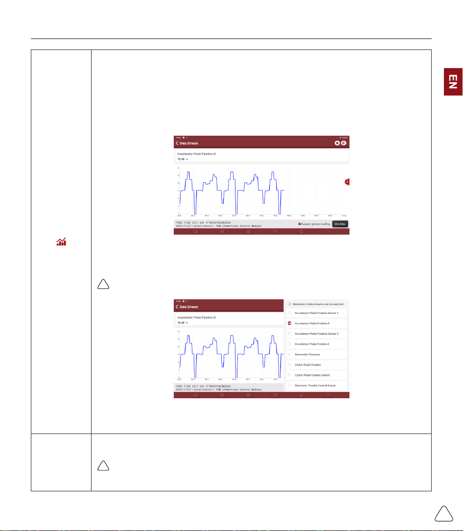
[ ]
Tap to display the current (single) data stream in waveform graph. On the waveform
graph page, you can do the following:
[Min/Max]: Tap to dene the maximum / minimum value. Once the value goes beyond
the specied value, the system will alarm.
[Customize]: Tap “<”on the right side of the screen, to dene the data stream option to
be viewed.
!
Note: Max 4 data streams can be displayed.
[Compare
Sample]
Tap to select the sample DS le. All the values you customized and saved in process of
DS sampling will be imported into the Standard Range column for your comparison.
!
Note: Before executing this function, you have to sample the values of data stream items
and save it as a sample Data Stream le.

www.thinkcar.com
THINKCAR
17
[Report]
Tap to save the value of current data stream.
[Record]
To record diagnostic data, for you to replay and review. Tap “Stop” button to end
reading.
The saved le follows the naming rule: It begins with vehicle type, and then the product
S/N and ends with record starting time. All diagnostic records can be replayed from
User Info -> My Report.
[Save
Sample]
To sample data stream. After sampling, recording and saving the data stream, each
time you review the data stream items, you will be able to call out the corresponding
sample data to overwrite the current standard range.
Tap it to start recording the sample data stream (Note: Only data stream items with
measurement units will be recorded). Once the recording process is complete, tap to
end recording, the system will automatically jump to the data revision screen.
Tap the Min./Max. value to change it. After modifying all desired items, tap Save to
save it as a sample DS le. All DS les are stored in User Info -> Data Stream Sample
e) Actuation Test
This function is used to test whether the execution components in the electronic control system can work
normally.
3.3 Maintenance
THINKTOOL supports matching, coding, programming of most vehicles’ programable modules, and
most commonly used maintenance and reset functions, including, Oil Reset, Elec. Throttle Adaption,
IMMO Service, Injector Coding, Break-pad Reset, Steering Angle Reset, ABS Bleeding, AFS Reset,
Battery Matching, A/T Learning, DPF Regeneration, EGR Adaption, TPMS Reset, Sunroof Initialization,
Suspension Matching, Gear Learning, Airbag Reset, ODO Reset, AdBlue Reset, A/F Reset, Coolant
Bleeding, Language Change, NOx Sensor Reset, Seat Calibration, Stop/Start Reset, Transport Mode,
Tyre Reset, Windows Calibration.
3.3.1 Oil Reset
The lightening of the car maintenance light indicates that the vehicle needs maintenance. Reset the
mileage or driving time to zero after the maintenance, so the maintenance light will vanish and the system
will start a new maintenance cycle.
3.3.2 Elec. Throttle Adaption
Elec. Throttle Adaption is to utilize the car decoder to initialize the throttle actuator so that the learning
value of the ECU returns to the initial state. By doing these, the movement of the throttle (or idle motor)
can be more accurately controlled, thus adjust the intake volume. Situations when throttle matching is

www.thinkcar.com
THINKCAR
18
needed:
a) After replacing the electronic control unit, the relevant characteristics of the throttle operation have not
been stored in the electronic control unit.
b) After the electric control unit is powered o, the memory of the electric control unit’s memory is lost.
c) After replacing the throttle assembly, you need to match the throttle.
d) After replacing or disassembling the intake port, the controlling of the idle speed by the coordination
between the electronic control unit and the throttle body is aected.
e) Although the characteristics of the idle throttle potentiometer have not changed, the intake volume has
changed and the idle control characteristics have changed at the same throttle openings.
3.3.3 Steering Angle Reset
To reset the steering angle, rstly nd the relative zero point position for the car to drive in straight line.
Taking this position as reference, the ECU can calculate the accurate angle for left and right steering.
After replacing the steering angle position sensor, replacing steering mechanical parts (such as steering
gearbox, steering column, end tie rod, steering knuckle), performing four-wheel alignment, or recovering
car body, you must reset the steering angle.
3.3.4 Battery Matching
This function enables you to perform a resetting operation on the monitoring unit of vehicle battery, in
which the original low battery fault information will be cleared and battery matching will be done.
Battery matching must be performed in the following cases:
a) Main battery is replaced. Battery matching must be performed to clear original low battery information
and prevent the related control module from detecting false information. If the related control module
detects false information, it will invalidate some electric auxiliary functions, such as automatic start &
stop function, sunroof without one-key trigger function, power window without automatic function.
b) Battery monitoring sensor. Battery matching is performed to re-match the control module and motoring
sensor to detect battery power usage more accurately, which can avoid an error message displaying on
the instrument panel.
3.3.5 ABS Bleeding
When the ABS contains air, the ABS bleeding function must be performed to bleed the brake system to
restore ABS brake sensitivity. If the ABS computer, ABS pump, brake master cylinder, brake cylinder, brake
line, or brake uid is replaced, the ABS bleeding function must be performed to bleed the ABS.
3.3.6 Break-pad Reset
If the brake pad wears the brake pad sense line, the brake pad sense line sends a signal sense line to the
on-board computer to replace the brake pad. After replacing the brake pad, you must reset the brake pad.
Otherwise, the car alarms.
Reset must be performed in the following cases:
a) The brake pad and brake pad wear sensor are replaced.
b) The brake pad indicator lamp is on.

www.thinkcar.com
THINKCAR
19
c) The brake pad sensor circuit is short, which is recovered.
d) The servo motor is replaced
3.3.7 DPF Regeneration
DPF regeneration is used to clear PM (Particulate Matter) from the DPF filter through continuous
combustion oxidation mode (such as high temperature heating combustion, fuel additive or catalyst reduce
PM ignition combustion) to stabilize the lter performance.
DPF regeneration may be performed in the following cases:
a) The exhaust back pressure sensor is replaced.
b) The PM trap is removed or replaced.
c) The fuel additive nozzle is removed or replaced.
d) The catalytic oxidizer is removed or replaced.
e) The DPF regeneration MIL is on and maintenance is performed.
f) The DPF regeneration control module is replaced.
3.3.8 Gear Learning
The crankshaft position sensor learns crankshaft gear machining tolerance and saves to the computer
to more accurately diagnose engine misres. If gear learning is not performed for a car equipped with
Delphi engine, the MIL turns on after the engine is started. The diagnostic device detects the DTC P1336
'gear not learned'. In this case, you must use the diagnostic device to perform gear learning for the car.
After gear learning is successful, the MIL turns o. After the engine ECU, crankshaft position sensor, or
crankshaft ywheel is replaced, or the DTC 'gear not learned' is present, gear learning must be performed.
3.3.9 IMMO Service
To prevent the car being used by unauthorized keys, the anti-theft key matching function must be
performed so that the immobilizer control system on the car identies and authorizes remote control keys
to normally use the car. When the ignition switch key, ignition switch, combined instrument panel, ECU,
BCM, or remote control battery is replaced, anti-theft key matching must be performed.
3.3.10 Injector Coding
Write injector actual code or rewrite code in the ECU to the injector code of the corresponding cylinder so
as to more accurately control or correct cylinder injection quantity. After the ECU or injector is replaced,
injector code of each cylinder must be confirmed or re-coded so that the cylinder can better identify
injectors to accurately control fuel injection.
3.3.11 TPMS Reset
After the tire pressure MIL turns on and maintenance is performed, the tire pressure resetting function
must be performed to reset tire pressure and turn o the tire pressure MIL. Tire pressure resetting must
be performed after maintenance is performed in the following cases: tire pressure is too low, tire leaks, tire
pressure monitoring device is replaced or installed, tire is replaced, tire pressure sensor is damaged, and
tire is replaced for the car with tire pressure monitoring function.

www.thinkcar.com
THINKCAR
20
3.3.12 Suspension Matching
This function can adjust the height of the body. When replacing the body height sensor in the air
suspension system, or control module or when the vehicle level is incorrect, you need to perform this
function to adjust the body height sensor for level calibration.
3.3.13 AFS Reset
This feature is used to initialize the adaptive headlamp system. According to the ambient light intensity, the
adaptive headlamp system may decide whether to automatically turn on the headlamps, and timely adjust
the headlamp lighting angle while monitoring the vehicle speed and body posture.
3.3.14 A/T Learning
This function can complete the gearbox self-learning to improve gear shifting quality. When the gearbox is
disassembled or repaired (after some of the car battery is powered o), it will lead to shift delay or impact
problem. In this case, this function needs to be done so that the gearbox can automatically compensate
according to the driving conditions so as to achieve more comfortable and better shift quality.
3.3.15 Sunroof Initialization
This function can set the sunroof lock o, closed when it rains, sliding / tilting sunroof memory function,
temperature threshold outside the car etc.
3.3.16 EGR Adaption
This function is used to learn the EGR (Exhaust Gas Recirculation) valve after it is cleaned or replaced.
3.3.17 ODO Reset
a) ODO reset is to copy, write, or rewrite the value of kilometers in the chip of odometer by using a car
diagnostic computer and data cable, so that the odometer shows the actual mileage.
b) Usually when the mileage is not correct due to the damaged vehicle speed sensor or odometer failure, it
is necessary to do ODO reset after maintenance.
3.3.18 Airbag Reset
This function resets the airbag data to clear the airbag collision fault indicator. When the vehicle collides
and the airbag deploys, the corresponding fault code of the collision data appears, the airbag indicator
lights up, and the fault code cannot be cleared. Since the data inside the airbag computer is disposable,
it is required that all new accessories must be replaced, but after performing this function, the data of the
airbag computer can be recovered and the fault code can be cleared, the airbag light will go out, and the
airbag computer can continue to use.
3.3.19 Transport Mode
In order to reduce power consumption, the following functions may be disabled, including limiting the
vehicle speed, not waking up the door opening network, and disabling the remote control key, etc. At this

www.thinkcar.com
THINKCAR
21
time, the transport mode needs to be deactivated to restore the vehicle to normal.
3.3.20 A/F Reset
This function is applied to set or learn Air/Fuel ratio parameters.
3.3.21 Stop/Start Reset
This function is used to open or close the automatic start-stop function via setting the hidden function in
ECU (provided that the vehicle has a hidden function and supported by hardware).
3.3.22 NOx Sensor Reset
NOx sensor is a sensor used to detect the content of nitrogen oxides (NOx) in engine exhaust. If the
NOx fault is re-initialized and the NOx catalytic converter is replaced, it is necessary to reset the catalytic
converter learned value stored in the engine ECU.
3.3.23 AdBlue Reset (Diesel Engine Exhaust Gas Filter)
After the diesel exhaust treatment uid (car urea) is replaced or lled up, urea reset operation is required.
3.3.24 Seat Calibration
This function is applied to match the seats with memory function that are replaced and repaired.
3.3.25 Coolant Bleeding
Use this function to activate the electronic water pump before venting the cooling system.
3.3.26 Tyre Reset
This function is used to set the size parameters of the modied or replaced tire.
3.3.27 Windows Calibration
This feature is designed to perform door window matching to recover ECU initial memory, and recover the
automatic ascending and descending function of power window.
3.3.28 Language Change
This function is used to change the system language of the vehicle central control panel.
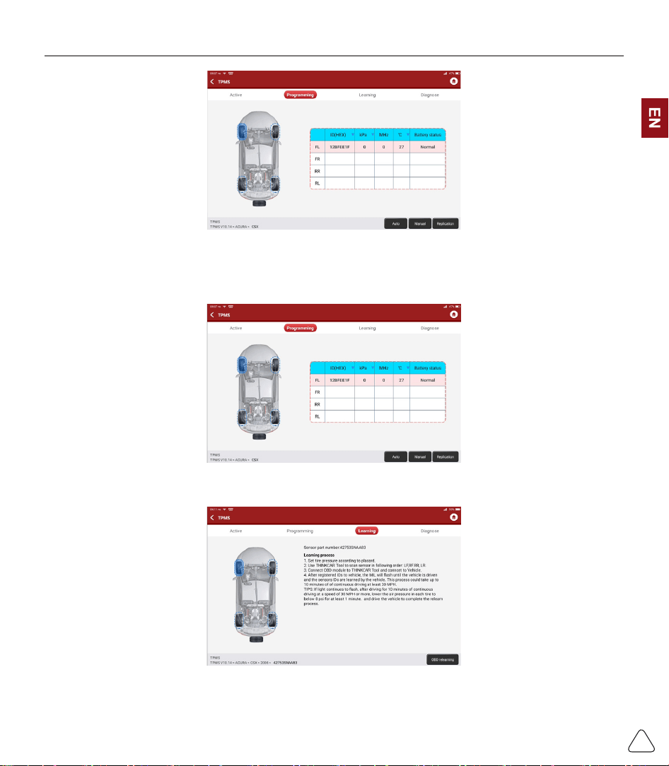
3.4 TPMS Diagnostics
THINKTOOL can work with wireless tire pressure diagnostic tool to perform TPMS activation, programming
and learning.
a) Activation: to activate the sensor's ID, wheel pressure, sensor frequency, tire temperature and battery
status.
www.thinkcar.com
THINKCAR
22
b) Programming: to program sensor data to a blank Thinkcar sensor, so as to replace a sensor that is in
low battery and does not function properly. There are three sensor programming methods available:
automatic, manual, and via activation replication.
c) Learning: to write the sensor ID into the vehicle ECU for sensor identication.
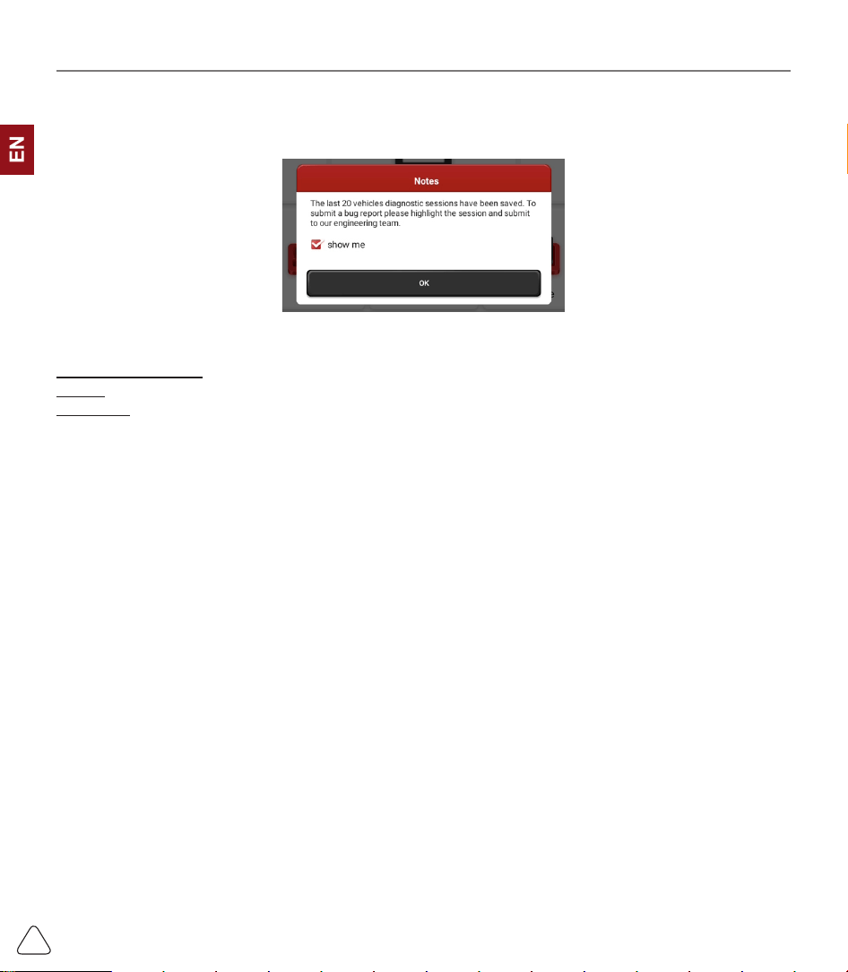
3.5 Diagnostic Feedback
If you encounter an unresolved problem or diagnostic software bug during diagnosis, you can revert
www.thinkcar.com
THINKCAR
23
the most recent 20 test records to Thinkcar Team. When we receive your feedback, we will analyze
and troubleshoot it in a timely manner, to improve the quality of our products and user experience. Tap
Diagnostic Feedback, the below pop-up message will appear:
Tap OK to enter the vehicle diagnostic feedback selection screen. There are three options:
Diagnostic Feedback: to show the list of all tested vehicle models
History: Tap to view all diagnostic feedback reverted and the processing progress.
Oine List: Tap to display all diagnostic feedback logs which have not been submitted successfully due to
network failure. Once the tablet gets a stable network signal, it will be uploaded to the server automatically.
In Diagnostic Feedback page, tap the diagnostic record of certain vehicle model or special function to next
step.
Tap Choose File to open the target folder and choose the desired diagnostic logs. Choose the failure type
and ll with the detailed failure description in the text box, and leave your telephone or email address. After
inputting, tap Upload Logs to revert feedback to us.
We will follow up your feedback as soon as we receive your diagnostic feedback, please keep an eye on
the progress and results of your diagnostic feedback in Diagnostic Feedback History.
3.6 Repair Info
3.6.1 Fault Code Enquiry
You can enquire the denition of OBD fault codes.
3.6.2 Vehicle Coverage Enquiry
You can enter the vehicle brand, model, year and other information to enquire the support functions and
diagnostic system.
3.6.3 Learning Course
You can view the operation playback of the special functions of each brand model, to help users study the
operation of the special functions online without connecting the vehicle.
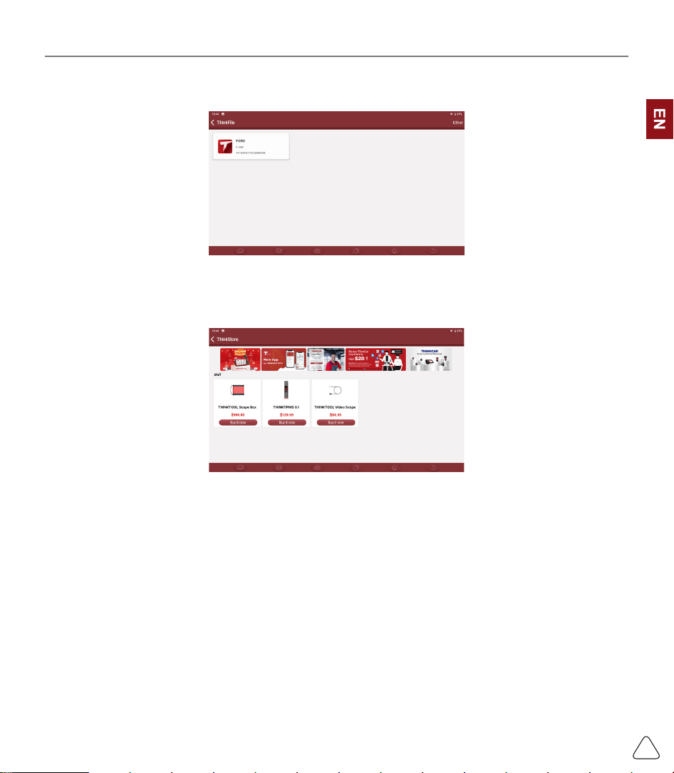
3.7 ThinkFile
It is used to record and establish the le of the diagnosed vehicles. The le is created based on the vehicle
www.thinkcar.com
THINKCAR
24
VIN and check time, including all VIN-related data such as diagnostic reports, data stream records and
pictures.
3.8 ThinkStore
ThinkStore, released by THINKCAR TECH, in which you can purchase hardware products.
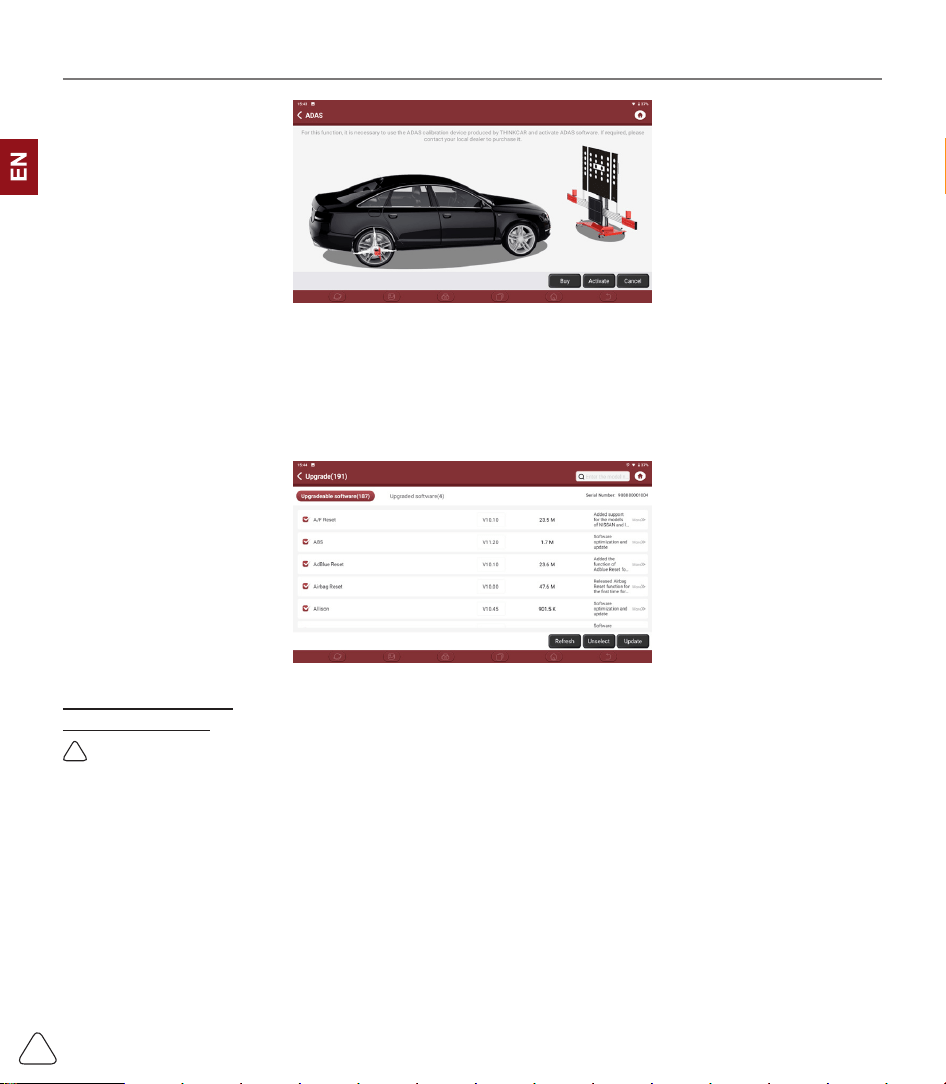
3.9 ADAS (Optional)
Advanced Driver Assistance System (ADAS) is an electronic component in a vehicle, including various
safety functions of the vehicle, such as automatic emergency braking (AEB), lane departure warning (LDW),
lane keeping assist, blind spot elimination, night vision camera and Adaptive lighting.
The function on the equipment is disabled by default, and the user needs to activate the function with an
activation card before using it. And this function needs to be matched with THINKCAR ADAS calibration
tools. Mainly used to calibrate various camera and radar of driver assistance systems, such as: front
camera for lane departure warning system, radar sensor for ACC and camera for adaptive headlights.
www.thinkcar.com
THINKCAR
25
4. Software Update
4.1 Upgrade all Software
In order to let you enjoy better functions and upgrade services, we recommend you make software
upgrades irregular. When there is a newer software version, the system will remind you to upgrade.
Click "Software Upgrade" to enter the upgrade center. There are two function tabs on the upgrade page:
Upgradeable software: A list of software that can be upgraded to newer versions.
Upgraded software: a list of software that has been downloaded.
!
Note: During the upgrade, please keep normal network connection. Upgrade many software may take a few
minutes, please wait.
If you need to remove certain software, please enter setting
->
diagnostic software clear
->
remove
software to operate.
5. Set Up
5.1 VCI
If several VCI connectors are registered on this THINKTOOL, this option allows you to choose one from
those.
www.thinkcar.com
THINKCAR
26
5.2 VCI Management
Used to choose Bluetooth communication mode or Wi-Fi communication mode.
5.3 Activate VCI
This item lets you activate a new VCI connectors or get help. Input the Serial Number and Activation Code,
and then tap “Activate” to activate it.
Once the VCI connector is activated, the serial number of it will be displayed in the list.
5.4 Fix VCI Firmware/system
Used to repair the VCI rmware. During the repair, please don’t power o or switch interfaces.
5.5 Data Stream Sample
This feature allows you to manage the recorded data stream sample les.
5.6 My Order
Used to manage order details.
5.7 Prole
Used to set and manage personal information.
5.8 Change Password
This item allows you to modify your login password.
5.9 Wi-Fi Settings
Set up Wi-Fi networks that can be connected.
5.10 Diagnostic Software Clear
This option can clear some cache les and free up the storage space.
www.thinkcar.com
THINKCAR
27
5.11 Business Information
Add the information of the workshop, to which the tool belongs, and it will be displayed to customers in the
diagnostic report.
5.12 Customer Management
Manage information of all customers, who did vehicle diagnostic on this equipment and display in turn.
5.13 Photo Album
This module saves the screenshots.
5.14 Screen Recorder
This module saves the screen recordings.
5.15 Settings
This option makes settings including Units, Language, Clear Cache, Mode Switch, Restore Factory
Settings, and Log Out.
6.FAQ
Q: Can I use the same type of charger to charge the tablet?
A: No, please use original charger. Our company is not responsible for any damage and economic loss
caused by using charger, which is not provided by THINKCAR.
Q: How to save power?
A: Please turn o the screen while the equipment isn’t used, set a shorter standby time, and decrease the
brightness of the screen.
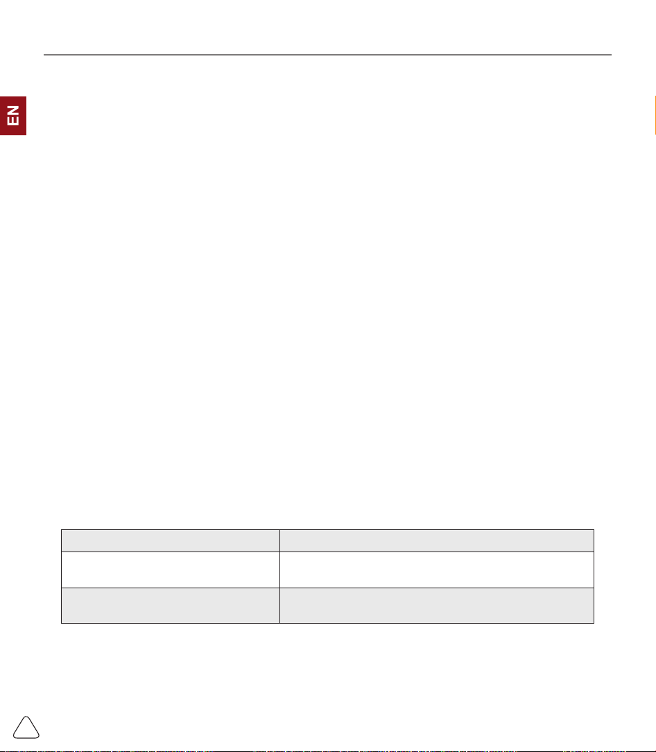
Q: The tablet cannot be turned on after charging
Passible reasons Solution
The equipment has not been used for
a long time, and the battery loss
Charge it for more than 2 hours before turning it on
Problem of Charger
If there is a quality problem, please contact the dealer or
after-sales service of THINRCAR.
Q: Why can’t make register?

www.thinkcar.com
THINKCAR
28
Passible reasons Solution
The equipment isn’t connected Please make sure the network is connected
Notes that your email has been
registered.
Use another email for register or log in with the username
registered by the email (If you forget the username, you
can retrieve it by email)
The email didn’t receive the verication
code during the registration
Check if the email is correct and get the verication code
again
Q: Why can’t log in?
Passible reasons Solution
The equipment isn’t connected Please make sure the network is connected
The user name or password is
incorrect
Check the user name and password
Contact THINKCAR after-sales service or regional sales
to retrieve the user name and password
Server problem Server maintenance, please try again later
Q: Why can't activate the equipment?
Passible reasons Solution
The equipment isn’t connected Make sure the network is connected
The serial number and activation code
are inputted wrong
Check the serial number and activation code and make
sure they are correct (Serial number 12 digits, activation
code 8 digits).
The activation code is invalid Contact THINKCAR after-sales service or regional sales
Notes that the conguration is empty Contact THINKCAR after-sales service or regional sales
Q: Notes: the equipment is not activated during update software ?
Passible reasons Solution
The VCI connector may not be
activated during registration
Use the serial number and activation code to activate the
connector
Steps are as follows: Click [Settings]
->
[Activate VCI]
Enter the correct serial number and activation code in the
interface, and click [Activate].
Q: Software upgrade failed.

www.thinkcar.com
THINKCAR
29
Passible reasons Solution
The equipment is not connected to the
Internet
Check its network connection
The user name or password is wrong
The equipment has not enough
memory
Check the user name and password
Uninstall irrelevant applications and delete uncommonly
used vehicle software (enter setting -> diagnostic
software clear -> remove software to operate)
Server problem Server maintenance, please try again later
Q: There is no power in the VCI dongle after connecting to the vehicle’s DLC port.
Passible reasons Solution
Poor contact of vehicle’s DLC port Plug out the VCI dongle, and then plug it in again
Too low voltage of the vehicle battery
• Recharge the vehicle battery.
• Replace the vehicle battery if it is damaged.
Damage of the VCI dongle Contact THINKCAR after-sales service to get support
Q: The tablet cannot establish a connection with the VCI dongle.
Passible reasons Solution
Poor contact of the VCI dongle
• Plug out the VCI dongle, and then plug it in again
• Perform the VCI Bluetooth pairing again
The rmware is damaged
Enter the settings and tap “Fix Connector Firmware/
System” to x the rmware
Q: How about non-standard OBDII VCI connector
A: There is a several non-standard adapters in the box. Follow the instructions to connect.
Q: Communication error with vehicle ECU?
A: Please conrm:
Whether the VCI is correctly connected and whether the vehicle ignition switch is ON.
If all are normal, send vehicle production year, model and VIN number by Feedback feature.
Q: Failed to enter into vehicle ECU system?
A: Please conrm:
Whether the vehicle is equipped with the system,whether the VCI is correctly connected, and whether
the vehicle ignition switch is ON.

www.thinkcar.com
THINKCAR
30
Q: What to do if the connector is missing
A: Contact THINKCAR after-sales service or regional sales.
Q: The downloaded diagnostic software is inconsistent with the serial number
A: There are several connectors registered under the equipment account, and the serial number of right
connector has not been selected.
Enter the settings-[VCI] and select the right serial number of connector. Delete the software with
problems, then enter the upgrade center to download the diagnostic software again.
