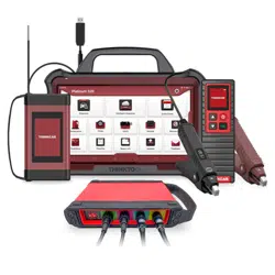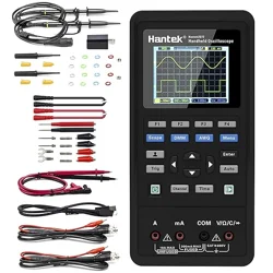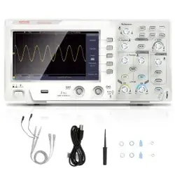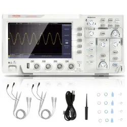
THINKTOOL Scope Box
All information, illustrations and specifications contained in this manual are based on the latest
information at the time of publication and we reserve the right to change without notice.
Quick Start Guide
Overall Description of Appearance and Interface
View all terminal ratings: To avoid fire and the impact of excessive current, please check all ratings
and labeling instructions on the product. Please refer to the product manual for details of the rating
before connecting the product.
Connect and disconnect the probe correctly: Connect to the probe correctly. The ground terminal
(or black line) of the probe is the ground phase. Do not plug in or out when the probe or test end is
connected to the voltage source.Disconnect the probe input terminal and probe reference
conductor from the circuit before disconnecting the probefrom the testing device.
The 4 channels of the Scope box and probe calibration signal ground is common ground, please
do not connect with non-ground line!
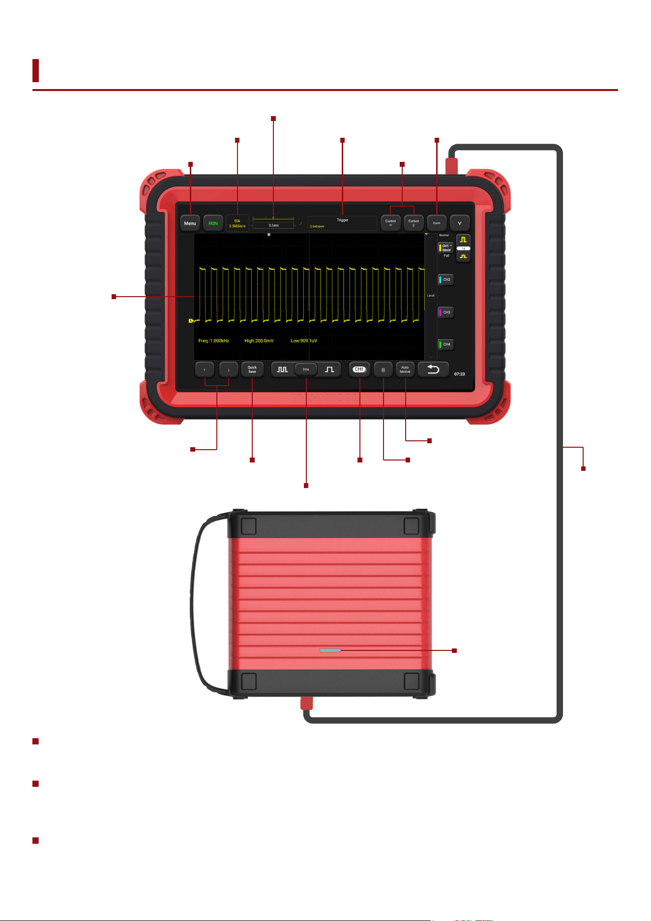
Indicator light
Main menu
Waveform area
Waveform selection
and motion
Fine adjustment
Crank angle cursor
Vehicle menu
Scope
Box cable
Cursor
measurements
Sample info
Waveform
quick save
Horizontal waveform positioning
Horizontal setting
Waveform
selection bar
Trigger instructions Zoom mode
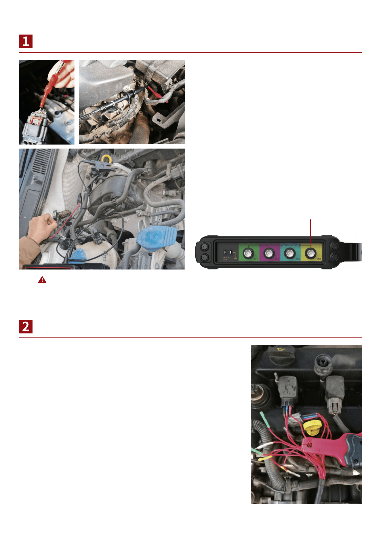
Wiring Instructions for Voltage Measurement
Description of Connection for Current Measurement
Clip the clamp to the battery negative (ground),
insert the needle into the charge connector of the
required test connection plug, and connect the
BNC wire signal end to the needle, or hook the
high-frequency probe on the needle;
According to different test positions, select the appropriate current
clamp, and select the appropriate gear, set the corresponding
attenuation in the probe of the scope box. Please connect the
BNC end to the scope box, clip the current clamp on the
measuring cable, and make the current direction indicated by the
head of current clamp consistent with the actual current direction.
Connect BNC terminal to the scope box.
Please connect probe to the BNC port.
Note: 4 channels are common ground, do not
connect to the wrong line.
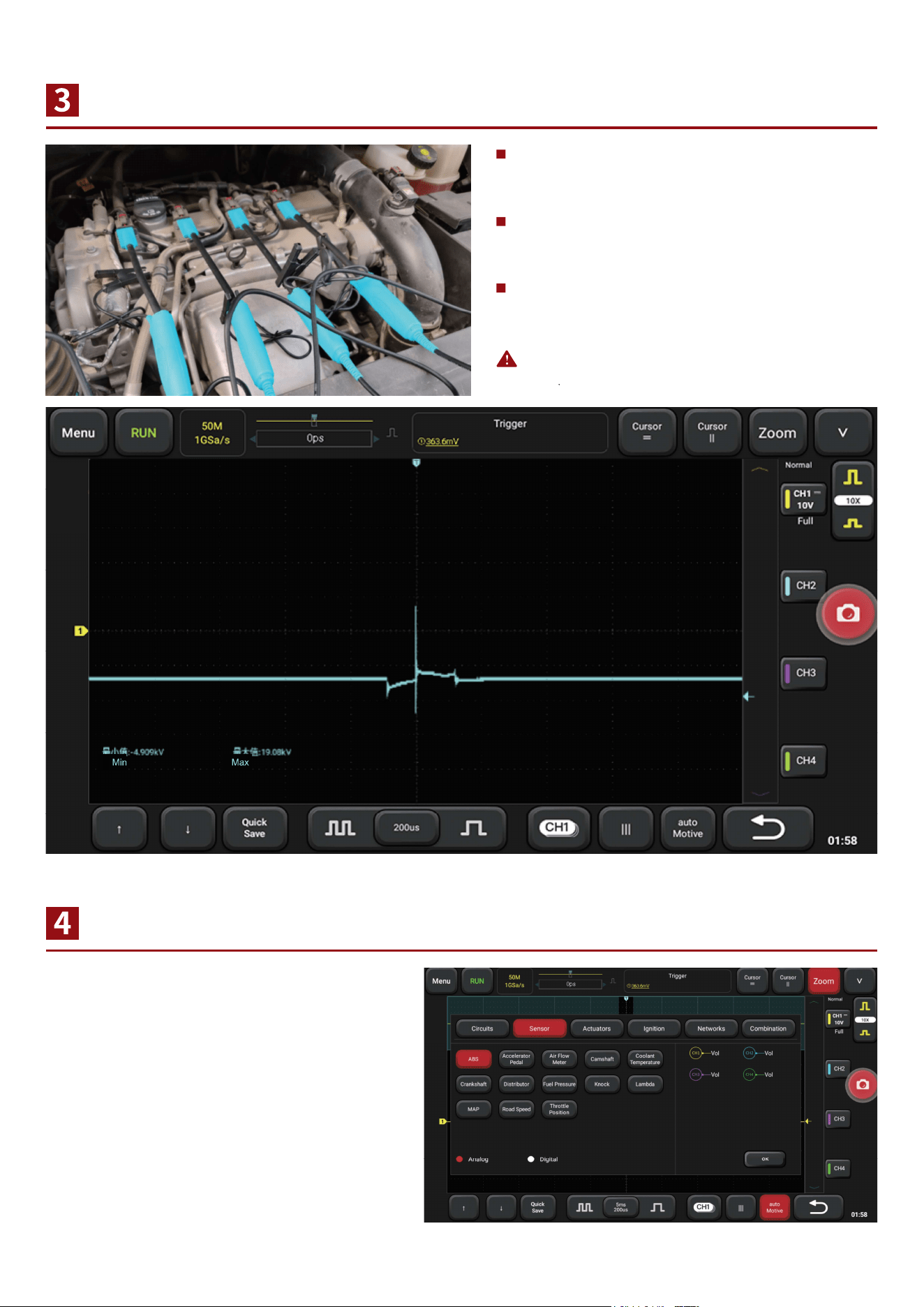
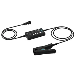
Instructions of Secondary lgnition Probe Connection
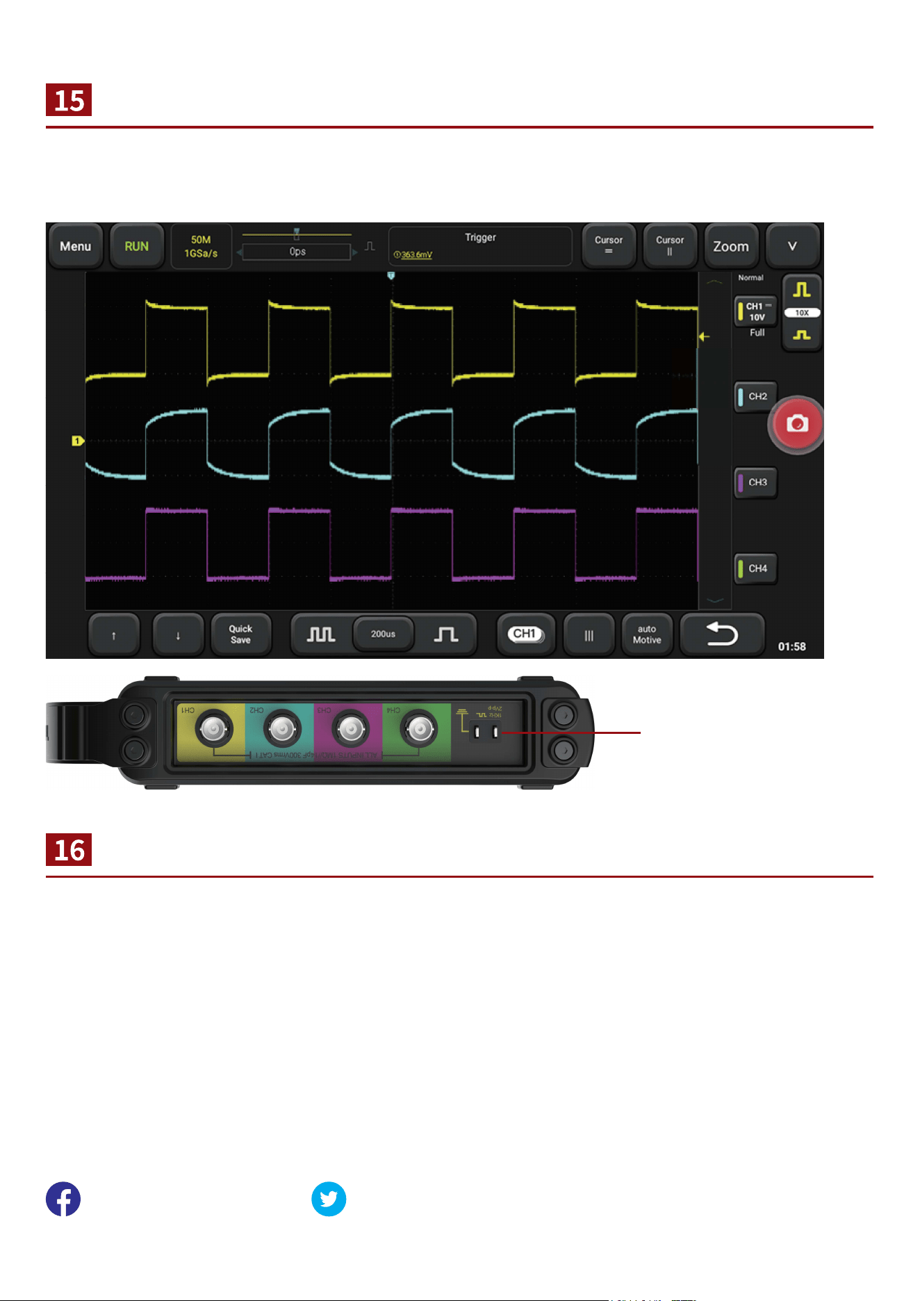
Use the Vehicle Menu
Note: Additional cost are required for Secondary Ignition
Probe
Please connect the BNC to the scope box,
and the ground clamp to the battery
negative(Ground);
For the model with cylinder wire, clamp the
secondary ignition probe on the cylinder
wire;
For COP independent ignition models,
place the ignition probe directly above the
ignition coil and ensure good contact.
Click the vehicle menu button, select the
type of test, and further select the test part
or signal. According to the requirements of
wiring, press "OK", then start the vehicle
test.
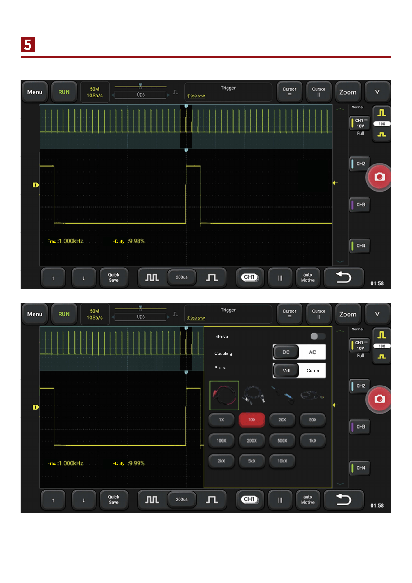
Open and Close Channels and Use Vertical Menu
Click the channel button to open or close the channel display, or to open the channel Settings menu.
Waveform Selection and Motion
Note: when there is a large number of waveform, you can click the lower channel button to open the channel
menu and select waveform. At this point, it's invalid to click on waveform selection.
Click on the waveform to select the waveform, holding down the waveform to move the waveform
horizontally or vertically.
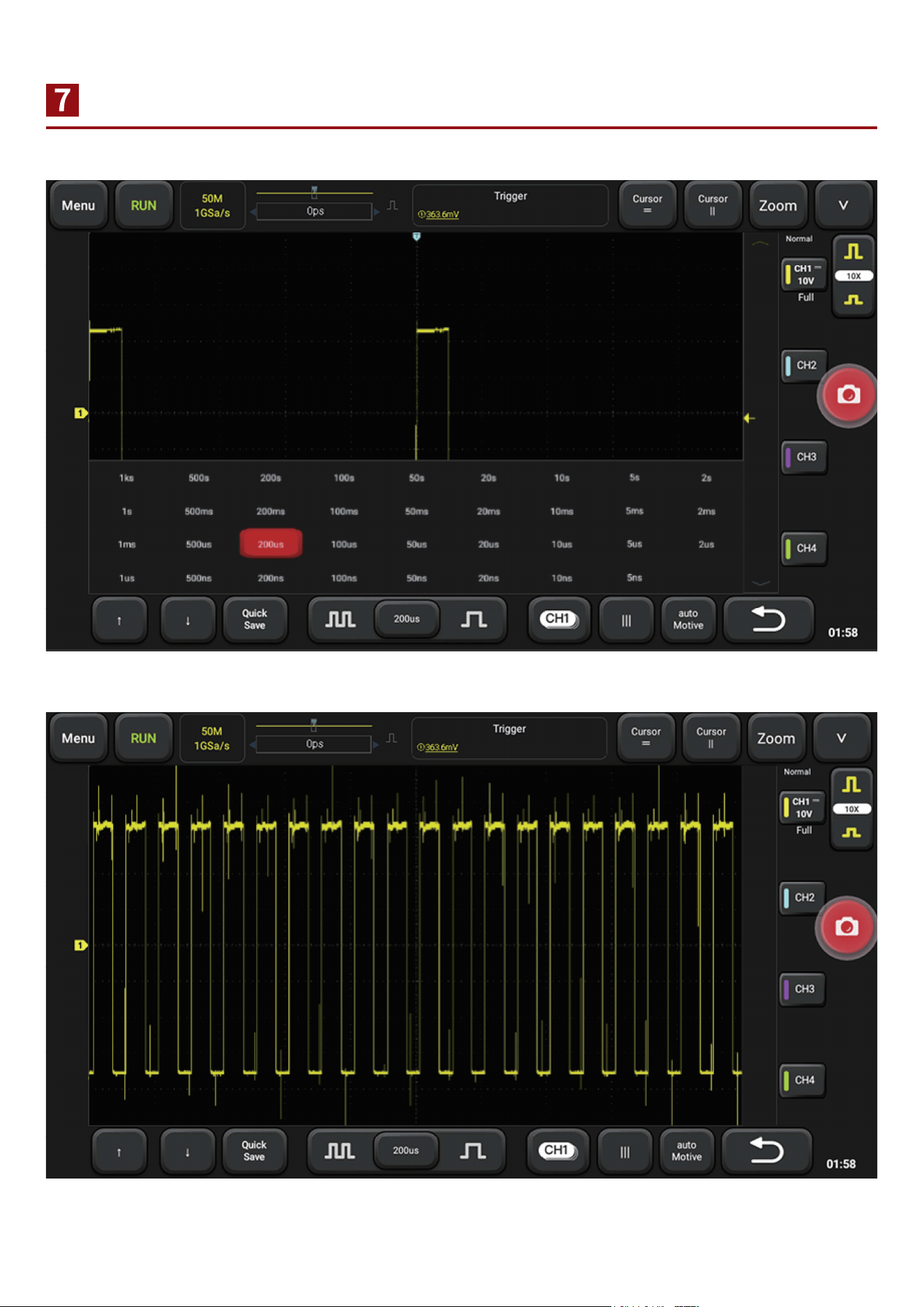
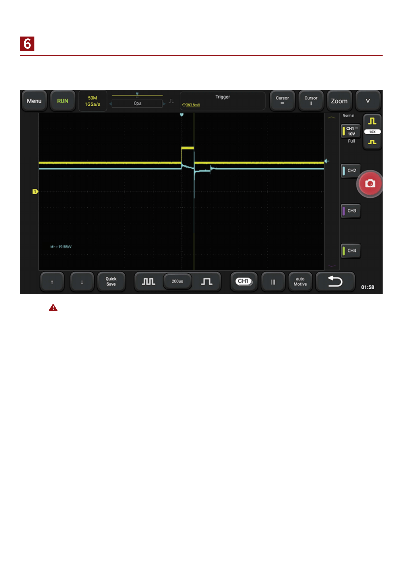
Adjust Size and Density of Waveform
When the waveform is too dense or too sparse, it is not conductive to observe.
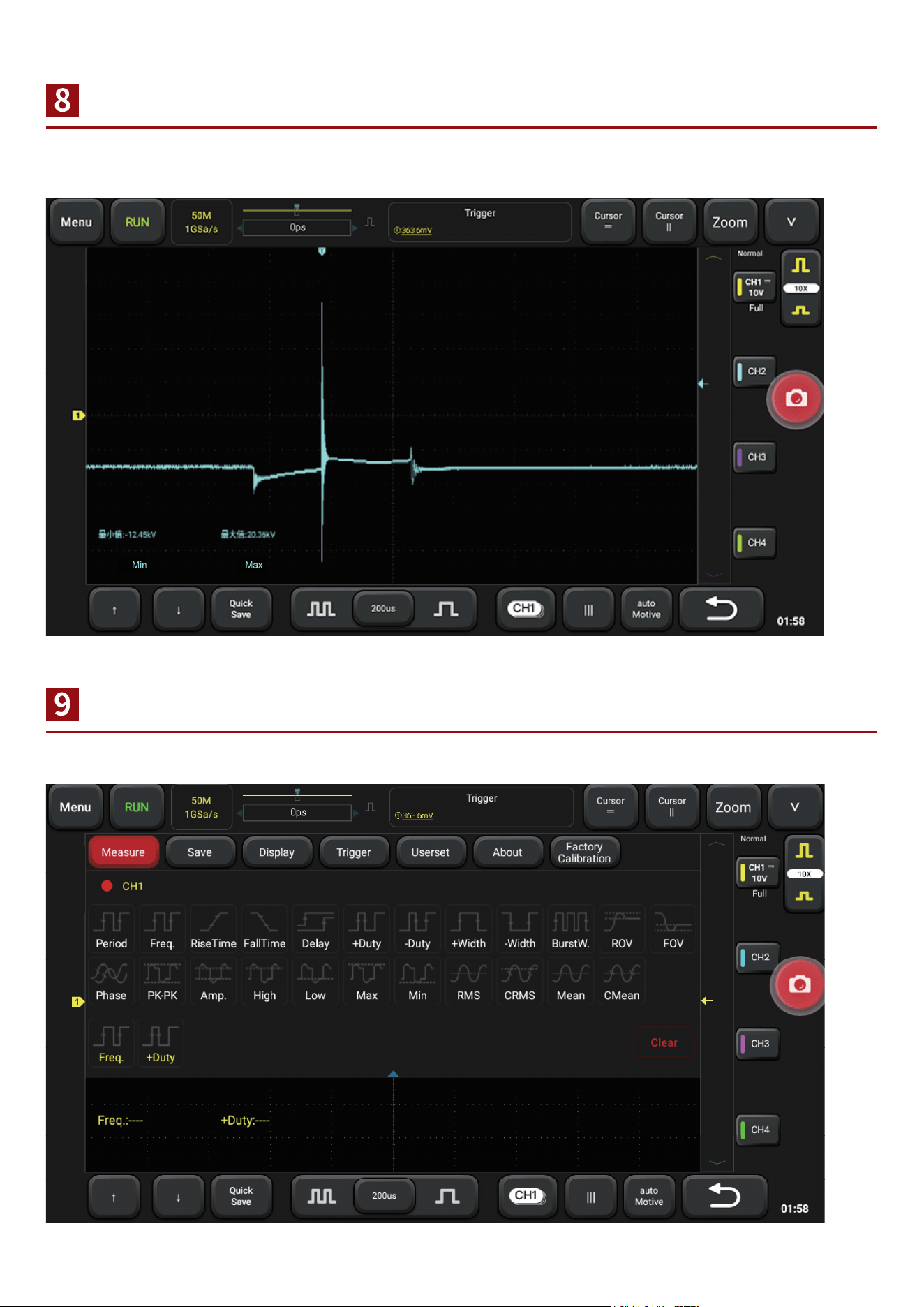
Adjust Synchronized Electric Level
Automatic Measurement of Waveform Data
When the waveform is unstable or cannot be synchronized, it is necessary to adjust the trigger
source or trigger level to make it synchronous and stable.
Open the main menu, select the measured channel in the measurement, and add it.
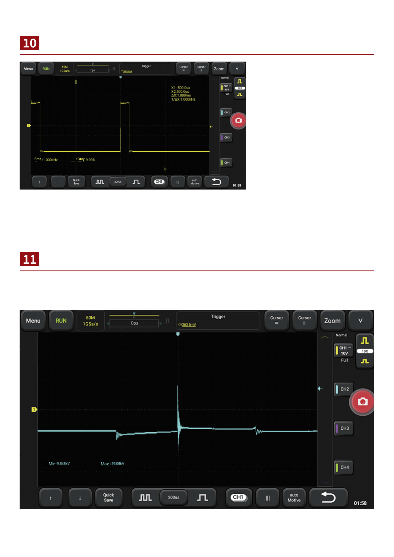
Cursor Measurements
Number of Waveforml attice
In the shortcut menu below, you
can quickly open the cursor, by
sliding the cursor, measure the
waveform of the voltage value,
voltage difference, time
difference, frequency, etc.
The horizontal direction represents the time, and the time is calculated according to the time base position of each lattice.
(the difference value between the two vertical cursors is the time. It can measure
period, other time difference or the engine speed, etc. lts inverse is the frequency).
The vertical direction represents the voltage. According to the voltage gear position of each channel
and the number of lattice at the zero point of the waveform distance from the channel, the voltage at
the required position can be calculated.
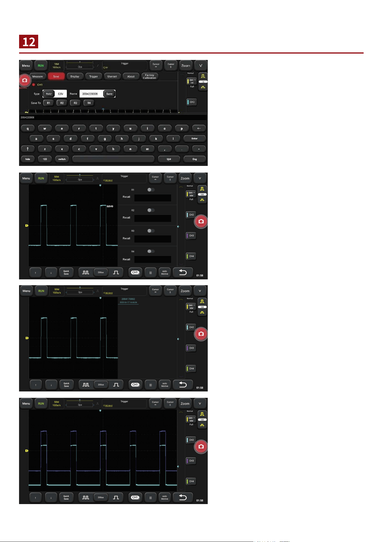
Save and View Waveform
Save: main menu - > save - > select
saving channel and saving type, input
waveform name - > click on “save”
View: switch the channel interface, open
Ref and select the waveform to be viewed.
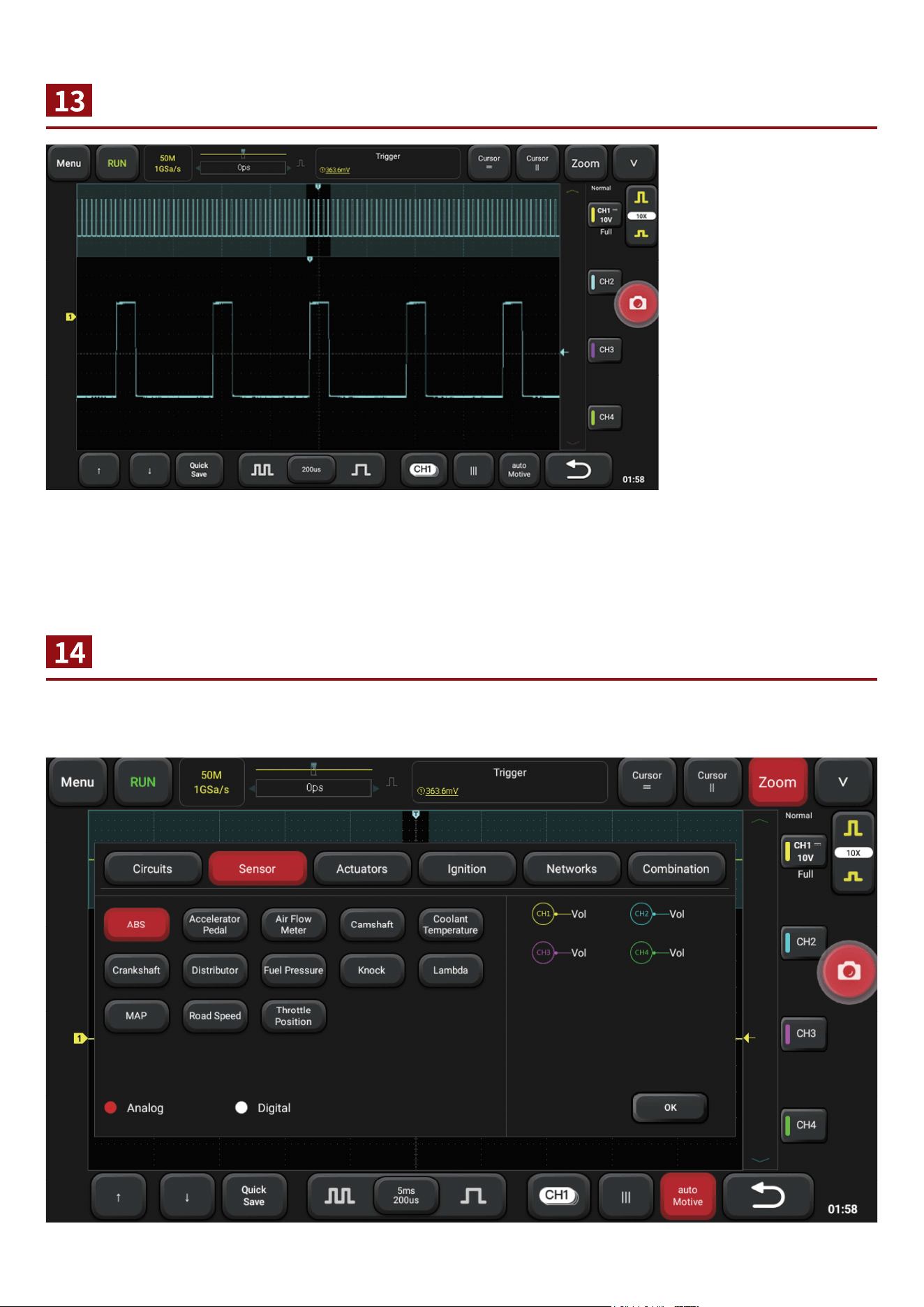
Zoom
Open and Cose Menu
Sometimes it is
necessary to check and
organize the waveform,
such as the entire
period of the
crankshaft/camshaft;
also , you need to look
at the details, such as
the waveform of one or
two waveform of the
crankshaft, and you
need to use zoom.
Click the "zoom" button
to enter/exit zoom.
Click the "menu" button to open/close the menu, or click anywhere blank to close the menu. Click the
function button in the menu to switch functions.
Probe Compensation
Warranty Card
While testing high frequency signal, it is necessary to calibrate the high frequency probe. Clamp the
probe at the calibration signal end and adjust the adjustable capacitance on the probe to make the
waveform at the same level (such as channel 3). Channel 1 and channel 2 are not normal waveform.
Please connect probe with probe
calibaration port.
1. The device is guaranteed for one year.
2. Before replacement, please ensure complete package; Before replacement/repair, please call the
service number to confirm the shipping address.
3. Product warranty starting date is based on the purchase date.
Service Line: 1-833-692-2766
Customer Service Email: [email protected]
Official Website: www.thinkcar.com
Products tutorial, videos, Q&A and coverage list are available on Thinkcar official website.
Follow us on
@thinkcar.official @ObdThinkcar