
PETROL FUEL INJECTION REMOVAL/
INSTALLATION KIT – BMW, MINI B36, B38, B48,
B58 ENGINES
MODEL NO: VS2081
Thank you for purchasing a Sealey product. Manufactured to a high standard, this product will, if used according to these
instructions, and properly maintained, give you years of trouble free performance.
IMPORTANT: PLEASE READ THESE INSTRUCTIONS CAREFULLY. NOTE THE SAFE OPERATIONAL REQUIREMENTS, WARNINGS & CAUTIONS. USE
THE PRODUCT CORRECTLY AND WITH CARE FOR THE PURPOSE FOR WHICH IT IS INTENDED. FAILURE TO DO SO MAY CAUSE DAMAGE AND/OR
PERSONAL INJURY AND WILL INVALIDATE THE WARRANTY. KEEP THESE INSTRUCTIONS SAFE FOR FUTURE USE.
1. SAFETY
WARNING! Ensure Health and Safety, local authority and general workshop practice regulations are adhered to when using tools.
WARNING!
Always use caution when working around fuel systems. The fuel in the fuel rail may be pressurised even if the
engine is not running.
9 IMPORTANT: These instructions are provided as a guide only. Always refer to the vehicle manufacturer’s service instructions, or a
proprietary manual, to establish the current procedure and data, also any warnings or cautions particular to the vehicle.
8 DO NOT use the set if any parts are missing or damaged.
8 DO NOT use this tool for any purpose other than that for which it is designed.
9 Switch off vehicle’s ignition and disconnect the battery before commencing work under the bonnet.
9 Never lay tools on the vehicle’s battery. This may short the terminals together, causing harm to yourself, the tools, or the battery.
9 Operate in a well ventilated area. DO NOT inhale fuel vapours.
9 Wear approved eye protection. A full range of personal safety equipment is available from your Sealey stockist.
NOTE: An Impact Socket must NOT be used with this tool. Stripped threads and bent thrust cups/rings are not accepted warranty
claims on this tool.
9 Keep children and other unauthorised persons away from the working area.
9 Keep yourself, tools, and test equipment away from hot engine parts.
9 Always keep a fire extinguisher that is suitable for fuel/electrical/chemical fires close by.
8 NEVER smoke or have open ames near vehicle.
9 Always relieve fuel pressure before disconnecting fuel lines from injectors.
9 Use a cloth to cover fuel line fittings when connecting or disconnecting fuel lines. Avoid contact with fuel.
9 Clean up all fuel spills immediately and dispose of all used cloths properly.
9 Maintain the tool components in good and clean condition for best and safest performance.
9 When work on the vehicle is finished, ensure all connections on vehicle are restored, and that there are no tools left in the engine bay.
9 Replace tools in the carrying case and store in a safe, dry, childproof location.
2. INTRODUCTION
Designed for easy removal and installation of plastic-bodied petrol injectors, found on BMW and MINI engines. Reduces the chance of damage
to the injectors. Applications: BMW and Mini engine codes B36, B38, B48, B58. Supplied in storage case. Equivalent OEM numbers 2 358 417
and 2 358 022.
3. SPECIFICATION
Model No.: ................................................................ VS2081
Nett Weight: ..................................................................4.3kg
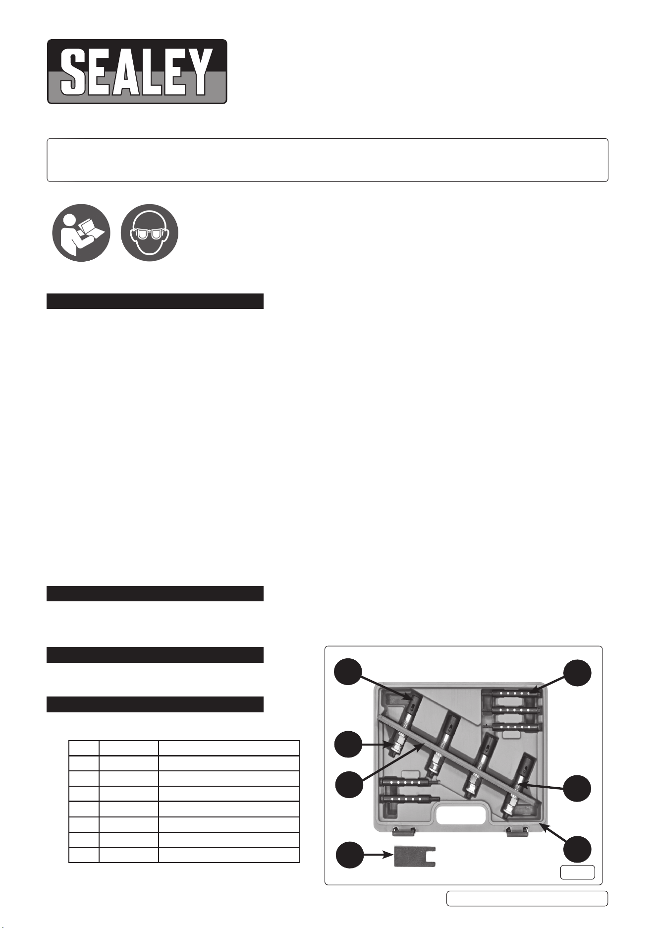
4. CONTENTS
VS2081 Issue 1 12/02/25
Original Language Version
© Jack Sealey Limited
Refer to
instructions
Wear eye
protection
Item Part no. Description
1 VS2081-01 Mounts for Injectors
2 VS2081-02 Threaded Sleeves
3 VS2081-03 Magnetic Mounting Sleeves
4 VS2081-04 Pull-Out Threads (L/H Thread)
5 VS2081-05 Base Plate
6 VS2081-SC Storage Case
7 VS2081-06 Setting Gauge
1
3
2
4
5
6
7
fig.1
5. OPERATION
5.1. PREPARATION
5.1.1. Remove engine bay covers if access restricted.
5.1.2. Remove intake air lter body and pipe work if access restricted.
5.1.3. Remove wiring for injectors.
5.1.4. Remove ignition coils and wiring.
5.1.5. Remove main fuel rail (keep clean and sealed).
5.2. ASSEMBLY (g.2)
5.2.1. Assemble components as shown in g. 2
5.2.2. Remove injector mounts (g.1.1) from the injector pulling tools and t to the injector/s to be removed. Ensure the lever of the injector
mounts are in the downward position when locked on to the injectors.
5.2.3. Assemble the baseplate (g.1.5) and the Magnetic Mounting Sleeves (g.1.3) on to the engine and t the Pull-Out Threads
(L/H Thread) (g.1.4).
5.2.4. Use a torque wrench and 24mm deep socket set the torque wrench to 7 Nm (this will produce a pulling (torsional) force of 2000 N on
the injector). Using the torque wrench turn the top puller nut.
5.2.5. WARNING!: If the torque wrench clicks, it indicates more than 7Nm is required to remove the injector which means the 2000 N pull
has been exceeded and the injector will need to be replaced.
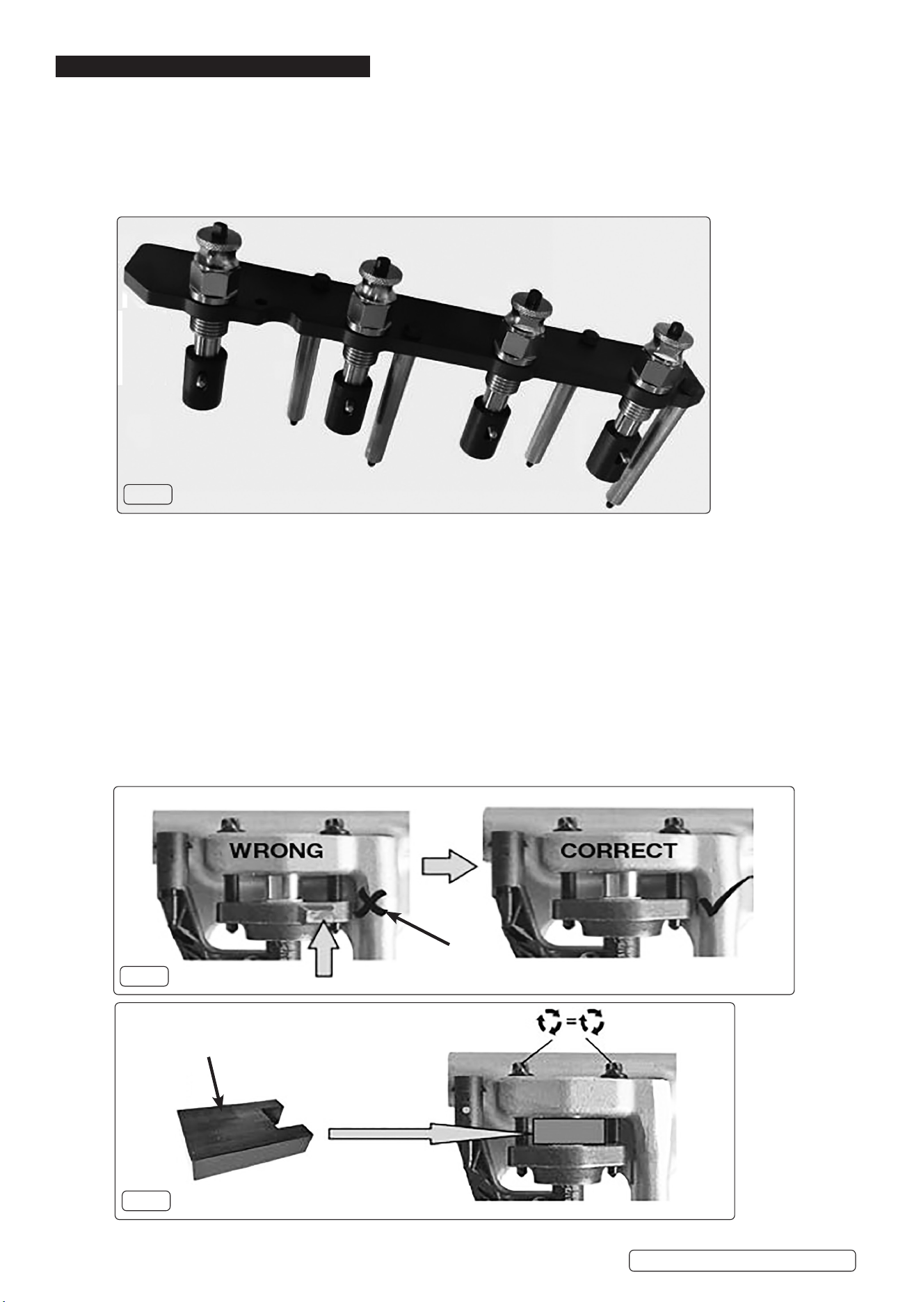
5.3. REASSEMBLY (g.3, Fig.4)
5.3.1. When reassembling the injectors they should rst be tted to the fuel rail. Setting gauge (g.1.7) is used to ensure the 2 injector bolts
are correctly and evenly tightened to avoid damage to the injector and rail.
5.3.2. The injectors and the injector holders must both be mounted in the correct orientation as shown in g.3.
5.3.3. Use Setting gauge (g.1.7), g.4) to ensure the 2 xing screws are evenly tightened. The injectors should still be able to rotate in
relation to the rail.
Setting Gauge
Note Incorrect
Orientation of
Tab
fig.2
fig.3
fig.4
Original Language Version
© Jack Sealey Limited
VS2081 Issue 1 12/02/25
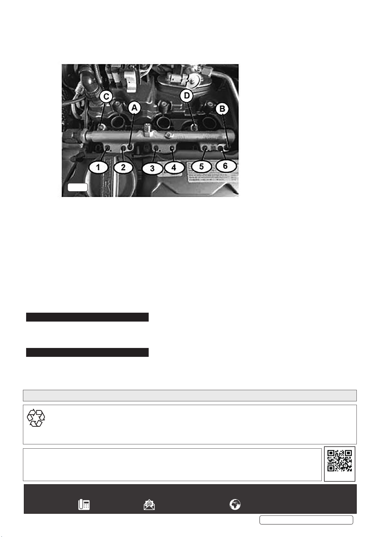
5.3.4. Refer to gure 5, (NOTE: refer to vehicle specic technical data to check torque settings) t the injector and rail assembly as shown
and tighten the rail xing bolts in the sequence shown 180º at a time. Check the rail is sitting evenly on the cylinder head. Refer to
gure 5 for an example of the stages involved in torquing the rail down.
5.3.5. WARNING!: MANUFACTURER CANNOT BE HELD RESPONSIBLE FOR USE OF INCORRECT TORQUE SEQUENCE. PLEASE
REFER TO MODEL SPECIFIC OEM DATA.
5.4. REINSTATING FUEL RAIL (g.5)
NOTE: Use a torque wrench set at 5Nm (refer to vehicle specic technical data to check torque settings).
WARNING: Manufacturer cannot be held responsible for use of incorrect torque sequence or settings. Please refer to model
specic OEM data.
5.4.1. Fit the injector and rail assembly as shown and hand tighten the rail xing bolts.
5.4.2. Use the torque wrench in the sequences 4.4.4 and 4.4.5 to check the rail is sitting evenly on the cylinder head. Refer to g.5
for an example of the stages involved in torquing the rail down.
5.4.3. Tighten xings A, B, C and D to 5 Nm. as sequences 4.4.4 and 4.4.5
5.4.4. Alternately turn xings A and B through 180
o
until the rail sits level onto the cylinder head.
5.4.5. Alternately turn xings C and D through 180
o
until the rail sits level onto the cylinder head.
5.4.6. Hand tighten the bolts 1 to 6.
5.4.7. In pairs, tighten 1&2, 3&4, 5&6 to 5 Nm and then turn all bolts another 90
o
of turn.
5.4.8. Loosen bolts A, B, C, and D and then re-torque to 5 Nm and add a further 90
o
of turn.
6. MAINTENANCE
6.1. Inspect all components for damage. DO NOT use damaged components.
6.2. After use, clean all components with a lightly oiled cloth and return to the carry case. Store in a dry location away from children.
7. END OF LIFE
7.1. Dispose of unit in accordance with local and national regulations and contents of page footer “Environment Protection”.
Original Language Version
© Jack Sealey Limited
VS2081 Issue 1 12/02/25
fig.5
Sealey Group, Kempson Way, Suffolk Business Park, Bury St Edmunds, Suffolk. IP32 7AR
01284 757500 sales@sealey.co.uk www.sealey.co.uk
ENVIRONMENT PROTECTION
Recycle unwanted materials instead of disposing of them as waste. All tools, accessories and packaging should be sorted, taken to
a recycling centre and disposed of in a manner which is compatible with the environment. When the product becomes completely
unserviceable and requires disposal, drain any fluids (if applicable) into approved containers and dispose of the product and fluids
according to local regulations.
Note: It is our policy to continually improve products and as such we reserve the right to alter data, specifications and component
parts without prior notice.
Important: No Liability is accepted for incorrect use of this product.
Warranty: Guarantee is 12 months from purchase date, proof of which is required for any claim.
Parts support is available for this product. Please email sales@sealey.co.uk or telephone 01284 757500
REGISTER YOUR
PURCHASE HERE
