FUEL INJECTOR PULLER & SERVICE KIT FOR
VAG 24PC
MODEL NO: VS2083
Thank you for purchasing a Sealey product. Manufactured to a high standard, this product will, if used according to these instructions,
and properly maintained, give you years of trouble free performance.
IMPORTANT: PLEASE READ THESE INSTRUCTIONS CAREFULLY. NOTE THE SAFE OPERATIONAL REQUIREMENTS, WARNINGS & CAUTIONS. USE
THE PRODUCT CORRECTLY AND WITH CARE FOR THE PURPOSE FOR WHICH IT IS INTENDED. FAILURE TO DO SO MAY CAUSE DAMAGE AND/OR
PERSONAL INJURY AND WILL INVALIDATE THE WARRANTY. KEEP THESE INSTRUCTIONS SAFE FOR FUTURE USE.
1. SAFETY
WARNING! Ensure Health and Safety, local authority and general workshop practice regulations are adhered to when using tools.
WARNING! Petrol fumes and battery gases are explosive, DO NOT smoke or allow a naked ame or sparks in the work area.
9 Keep a dry chemical (class B) re extinguisher near to the work area.
9 Avoid re hazard by using caution when disconnecting fuel lines, as some spillage is inevitable.
8 DO NOT let fuel spill onto a hot engine.
9 Before repairing the fuel system, turn o the ignition switch and disconnect the battery as per manufacturer’s procedure. Never
disconnect the battery while the engine is running.
WARNING! Wipe up fuel spills immediately.
8 DO NOT use tools if damaged.
9 Maintain tools in good and clean condition for best and safest performance.
9 Ensure that a vehicle which has been jacked up is adequately supported with axle stands.
9 Wear approved eye protection. A full range of personal safety equipment is available from your Sealey dealer.
9 Wear suitable clothing to avoid snagging. DO NOT wear jewellery and tie back long hair.
9 Keep children and unauthorised persons away from the work area.
8 DO NOT attempt to start engine with the injectors removed.
9 Always display a warning notification on steering wheel when engine components have been removed.
9 Account for all tools and parts being used and DO NOT leave them in or near the engine.
9 Ensure all pieces are returned to the case and store this in a safe, dry, childproof location.
▲ IMPORTANT: These instructions are provided as a guide only. Always refer to the vehicle manufacturer’s service instructions, or a
proprietary manual, to establish the current procedure and data.
WARNING: The warnings, cautions and instructions in this manual cannot cover all possible conditions and
situations that may occur. It must be understood that common sense and caution are factors which cannot be
built into this product, but must be applied by the operator.
2. INTRODUCTION
Comprehensive kit designed for quick and easy removal of injectors and injector seals. For petrol and diesel injectors and injector seals
on 1.4SDi/TDi, 1.9D/SF/TDi/TDi(PD), 2.0Ti/TDi(PD), 2.8TDi(PD) and FSi injectors found on VAG engines. Equivalent OEM number
T10133 and T10163. Supplied in a storage case.
3. SPECIFICATION
MODEL NO: VS2083 DIESEL
Applications: 1.4 SDi/TDi | 1.9D/SDi/TDi (PD) | 2.0TDi (PD) 4-valves 2.5 TDi 2.5TDi (PD) | 2.8TDi (PD) 2.7/3.0TDi (PD.
Contents: Large Injector Remover, 2-Leg Injector Remover, Injector Remover Adaptor (x3), Slide Hammer, 300mm Slide
Hammer Extension Bar, 110mm Slide Hammer Extension Bar, Cleaning Brush, Teon®Ring Assembly Cone,
Teon®Ring Assembly Sleeve, Teon® Ring Calibration Sleeve (x2), Injector Installer, Teon® Ring Spacer Sleeve,
Support Ring Locking Plate, Support Ring Assembly Cone, Support Ring Calibration Sleeve, Injector Remover
Bridge, Support Ring Calibration Sleeve, Oset Adaptor, Hook Adaptor, 22mm Adaptor, 17mm Adaptor
Nett Weight: 3kg
NOTE: Although the injectors don’t suer seizure like other types, the removal can be tricky due to limited space. This can sometimes
lead to technicians using unsuitable tooling which can result in damage to the injectors themselves or the solenoids. The set is
supplied in a sturdy blow mould case.
Refer to
instruction
manual
Wear a face
shield
Wear protective
clothing
VS2083 Issue 1 14/01/2025
Original Language Version
© Jack Sealey Limited
Wear protective
gloves
Wear ear
protection
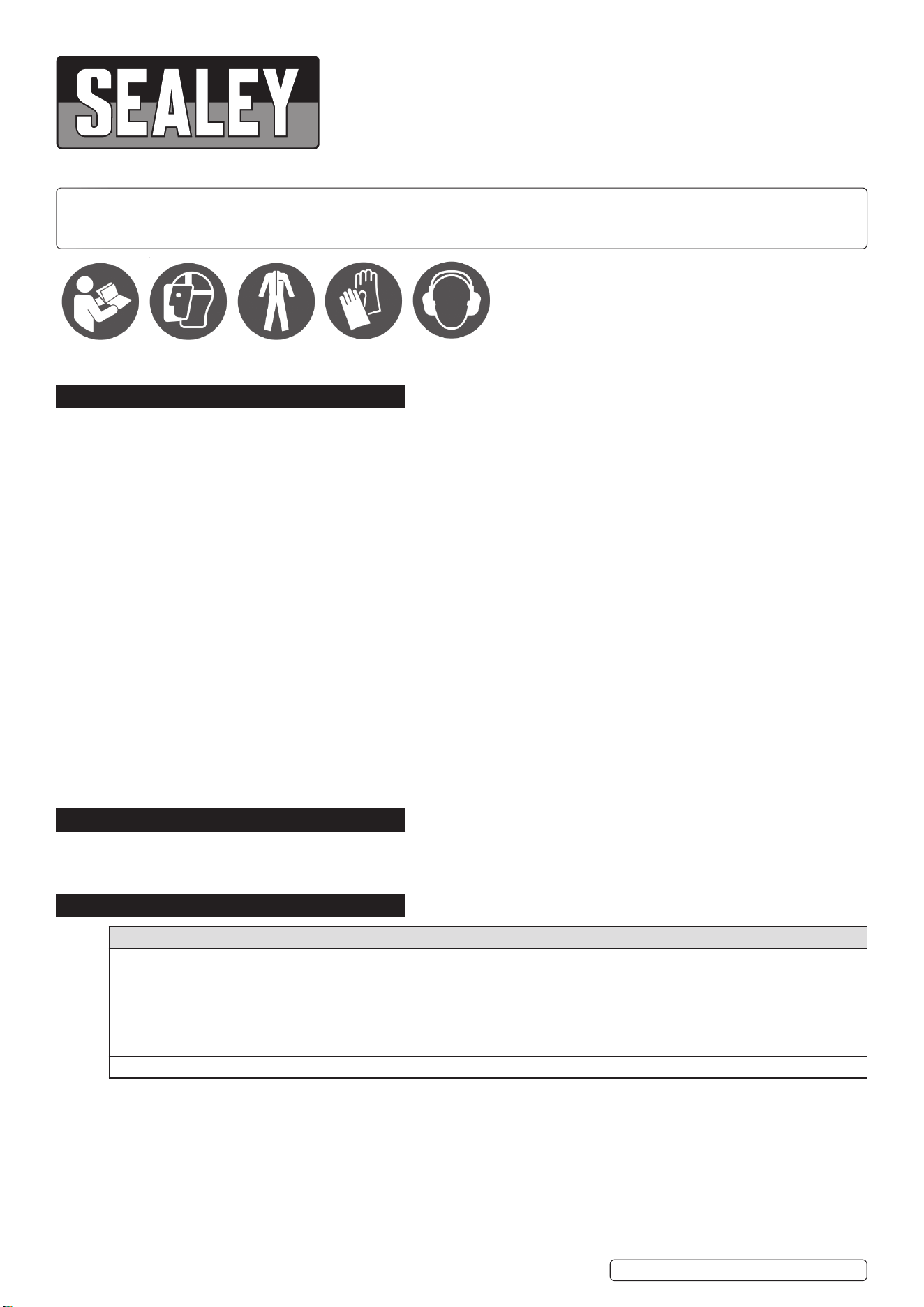
4. CONTENTS
5. OPERATION FOR DIESEL
As the set provides pulling methods for a number of dierent engine applications, the manufacturer’s documentation or workshop
manual must be referred to before the injector(s) can be removed. For example, the cam cover must be removed, in some applications
the camshaft has to be set to a particular position, rocker arms may have to be removed, or the rocker arm shaft may have to be
removed. When retting the injector or a new injector, pay particular attention to the manufacturer’s installation sequence, regarding
the pressing of the injector unit into the head, the alignment of the injector unit, the tightening sequence of the securing bolts and
any nal adjustment of the rocker arm setting (usually using a dial gauge).The kit includes two methods of pulling: using the direct
overhead grip (5) or the oset or hook adaptors (4 and 7). Use the suitable method according to the design of PD injector and how it is
secured to the cylinder head.To ensure dirt, oil or carbon does not enter the fuel system, clean all around the injector(s) to be removed,
and around the fuel lines, etc.Assemble the slide hammer by screwing 2-1,2-2 onto slide hammer shaft 4.
Original Language Version
© Jack Sealey Limited
VS2083 Issue 1 14/01/2025
MODEL NO: VS2083 PETROL
Applications: FSI: 1.4, 1.6, 1.8, 2.0, 2.7 V6, 3.0 V6, 3.2 V6, 3.6 V6, 4.2L V8
Contents: Injector Remover 2 Leg, Injector Remover (x3), Slide Hammer, Cleaning Brush, Teon Ring Assembly Cone,
Teon Ring Assembly Sleeve, Teon Ring Calibration Sleeve (x2), Injector Installer, Teon Ring Spacer
Sleeve, Support Ring Locking Plate, Support Ring Assembly Cone, Support Ring Calibration Sleeve (Single
Knurl), Injector Remover Bridge, Support Ring Calibration Sleeve (Double Knurl).
Nett Weight: 2.53kg
fig.
1A
VS2083-05
Item Part No. Description
1.1 VS2083-1.1 Injector installer
1.2 VS2083-1.2 Special knob for injector installer
2.1 VS2083-2.1 Slide hammer
2.2 VS2083-2.2 Slide hammer rod
3.1 VS2083-3.1 Injector remove bridge
3.2 VS2083-3.2 Injector remove bridge rod
4 VS2083-04 Long threaded shaft for slide hammer
5 VS2083-05 Direct overgrip
6 VS2083-06 Leg
7 VS2083-07 Hook adaptor
8 VS2083-08 Injector remover
9 VS2083-09 Injector remover
10.1 VS2083-10.1 Injector remover (2 Leg)
10.2 VS2083-10.2 Spacer for injector remover
10.3 VS2083-10.3 Injector remover leg
11 VS2083-11 Injector remover
12 VS2083-12 Cleaning brush
Item Part No. Description
13 VS2083-13 Support ring calibration sleeve
14 VS2083-14 Support ring calibration sleeve
15 VS2083-15 Teon ring spacer sleeve
16 VS2083-16 Teon ring assembly sleeve
17 VS2083-17 Teon ring calibration sleeve
18 VS2083-18 Teon ring calibration sleeve
19 VS2083-19 Support ring locking plate
20 VS2083-20 Support ring assembly cone
21 VS2083-21 Teon ring assembly cone
22 VS2083-22 Support ring calibration sleeve (a)
23 VS2083-23 Support ring calibration sleeve (b)
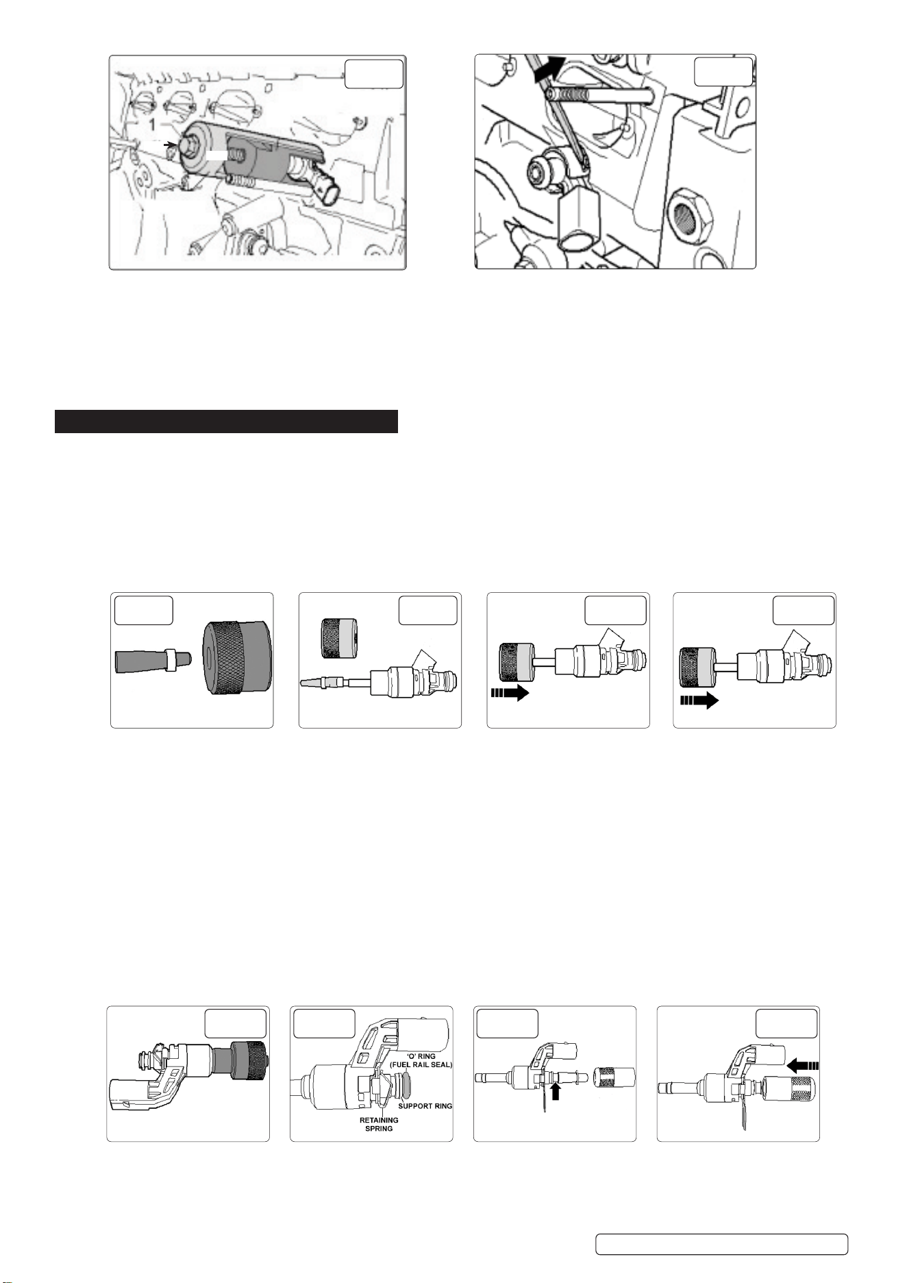
USING THE DIRECT OVERHEAD GRIP
Once access has been gained to the injector unit to be removed (refer to manufacturer’s documentation — see above),
pull ball stud out of the top of the injector unit (if tted). Undo the injector unit securing bolts using the special spline bit.
Fit the Direct Overhead Grip (5) over the injector inserting the feet into the bolt holes on the injector unit. (Refer to diagram)
Turn the puller spindle g1A(A) down lightly onto the top of the injector unit to apply slight pressure.Then hand-tighten the lock nut
g.1A(B).Screw the shaft of the slide hammer onto puller Spindle g.1A(A). Then pull injector unit upwards out of cylinder head with
careful, steady use of the slide hammer.
6. OPERATION FOR PETROL
6.1. Technical Description
6.2. VS2083 FSi Injector Remover/Installer and Service Kit contains the specialised tools required for the removal and installation of the
high pressure injectors from the current FSi/TFSi engines tted in AUDI, SEAT, SKODA and VOLKWAGEN models.
6.3. In addition the kit includes the special tting and calibration tools required when tting new seals and support rings on the injectors.
6.4. The tools within the kit are used in various combinations dependant on the engine and injector design. This instruction can only provide
a guide on the use of the various tools and reference should always be made to the appropriate workshop instructions for the engine
being worked on and a visual examination of the injector to establish the correct selection of tools from the kit, particularly with regard
to replacement and tting of new seals.
6.5. The technical instructions are divided into four sections:
Section 7 - Injector parts identication/assembly
Section 8 - Injector Removal
Section 9 - Seal Replacement.
Section 10 - Injector Installation.
7. PARTS ID / INJECTOR ASSEMBLY
WARNING! - FUEL SPILLAGE: Be prepared for residual fuel in the fuel rail to drain out as the fuel is removed. ENSURE NO
SOURCE OF FLAME OR SPARK IS CLOSE BY AND CLEAN UP SPILLAGE IMMEDIATELY.
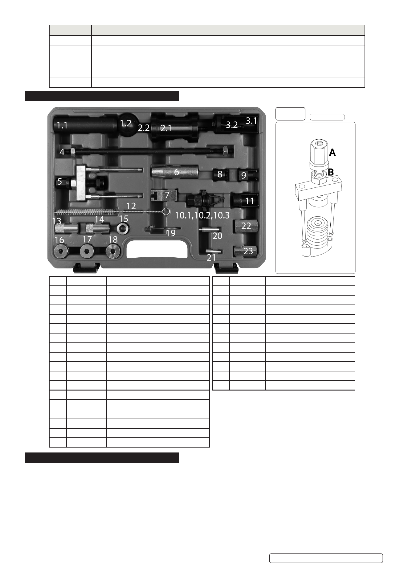
(g.2)TypicalInjectorReplacementPartsSetExample2.0FSiengineinjector.
When this injector is tted in the cylinder head, the assembly is as follows (g.2).
7.1. FSi injectors are located in the cylinder head and fuel is supplied via a fuel rail which can be an intake manifold/fuel rail assembly.
Injectors can only be accessed after removal of the manifold/fuel rail assembly and therefore some disassembly and hose
disconnections are required.
7.2. Having gained access to the injectors unplug the electrical connections from the injectors.
7.3. RemovalTools-Injector
7.4. If the complete injector assembly cannot be removed from the cylinder head easily by hand and there is a need to use
Removal Tools, the injector support ring must be removed in order to fit the appropriate Removal Adaptor into the groove in
the injector.
7.5. The injector removal tools available with the kit are listed as follows:
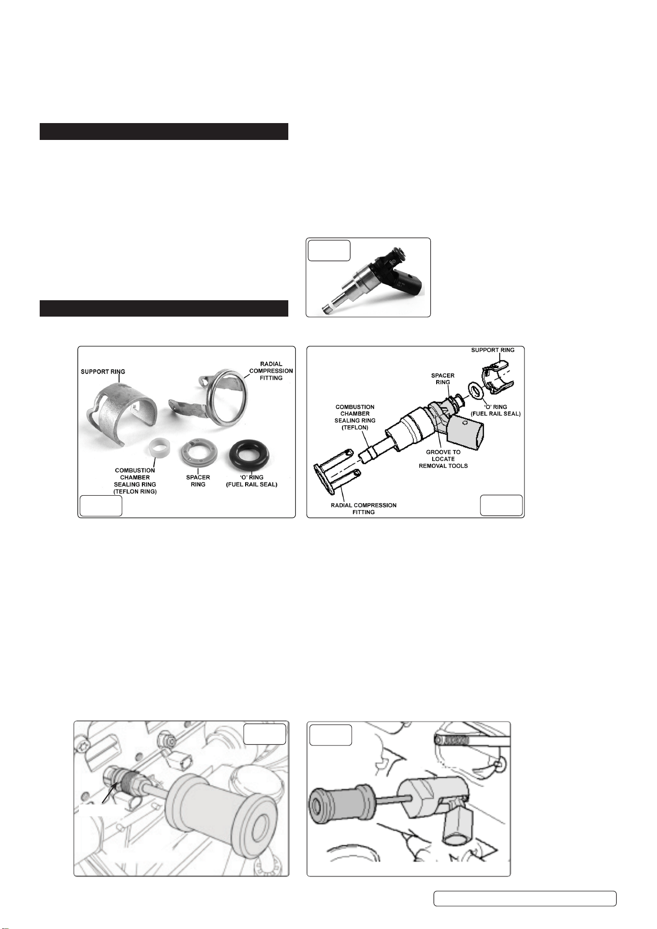
a) VS2083.10.1, 10.2,10.3 Remover 2 Leg - use in conjunction with VS2083.10.4 (fig.4)
b) VS2083.2-1, 2-2, Remover Adaptor - use in conjunction with VS2083.04 (fig.5) or VS2083.3-1, 3-2 (fig.6).
c) VS2083.2-1, 2-2 Slide Hammer.
d) VS2083.8 Remover Adaptor - use in conjunction with VS2083.2-1,2-2.
e) VS2083.9 Remover Adaptor - use in conjunction with VS2083.2-1, 2-2, 4.
f) VS2083.3-1, 3-2 Remover Bridge.
Original Language Version© Jack Sealey Limited
VS2083 Issue 1 14/01/2025
fig.
1
fig.
2
fig.
3
fig.
4
2.1
4
10-1,2,3
fig.
5
2.1
11
4
7.6. REMOVING INJECTOR
7.7. When the injector is tted in the cylinder head the radial compensation tting is ‘clipped’ onto the support ring and must be detached. A
suitable screwdriver can be used to lever the tags of the radial compensation tting out of the support ring in order that it can be pulled
o the injector (g.7). It is not unusual for these tags to break during release, or for the radial compensation tting to be destroyed
during removal of a stubborn injector, and therefore this tting will require replacement.
7.8. Remove the support ring o the injector, select the appropriate combination of removal tools from the VS2083 kit and t them on to the
injector in the groove position provided.
Note: When using the slide hammer, use ‘restrained’ impact action. Heavy blows should not be necessary.
8. SEAL REPLACEMENT
NOTE: The combustion chamber sealing ring (Teon ring) MUST ALWAYS be replaced - DO NOT grease or apply any lubricant to the
new seal during installation on the injector or when tting the injector to the cylinder head.
8.1. Seal Replacement Tools - Combustion Chamber Sealing Ring (Teon Ring).
8.2. The installation tools required for the combustion chamber sealing ring are listed as follows:
a) VS2083.05 Assembly Cone
b) VS2083.06 Assembly Sleeve (No.1)
c) VS2083.07 Calibration Sleeve (No.2)
d) VS2083.08 Calibration Sleeve (No.3)
e) VS2083.11 Spacer Sleeve
8.3. REMOVING OLD RING
8.3.1. Carefully remove the old teon ring (cut with razor blade or lever o with suitable screwdriver), and check that the groove for the ring
and the continuous ridge at the bottom of the groove, are not damaged.
NOTE: The injector must be replaced if the groove is damaged.
8.3.2. Clean o any combustion residue in the groove or on the injector shaft using a clean cloth only.
8.3.3. RING INSTALLATION
8.3.4. Push the new teon ring onto VS2083.05 Assembly Cone using VS2083.06 Assembly Sleeve (No.1) with the knurled side of the Sleeve
facing towards the ring (g.9).
8.3.5. Now turn the sleeve around (knurled side facing away from the ring) and use it to slide the ring smoothly o the cone into the groove in
the injector. DO NOT use any lubricants (g.10).
8.3.6. The teon ring is expanded as it is installed on the Assembly Cone and tted into the groove, and therefore must be compressed in a
two stage procedure, after it is tted in the groove.
8.3.7. Stage 1 - Using VS2083.07 Calibration Sleeve (No.2), slide the Sleeve over the injector shaft whilst simultaneously rotating it 180°,
inserting it as far as it will go applying moderate force only. Then pull the Sleeve back, again rotating it 180° (g.11).
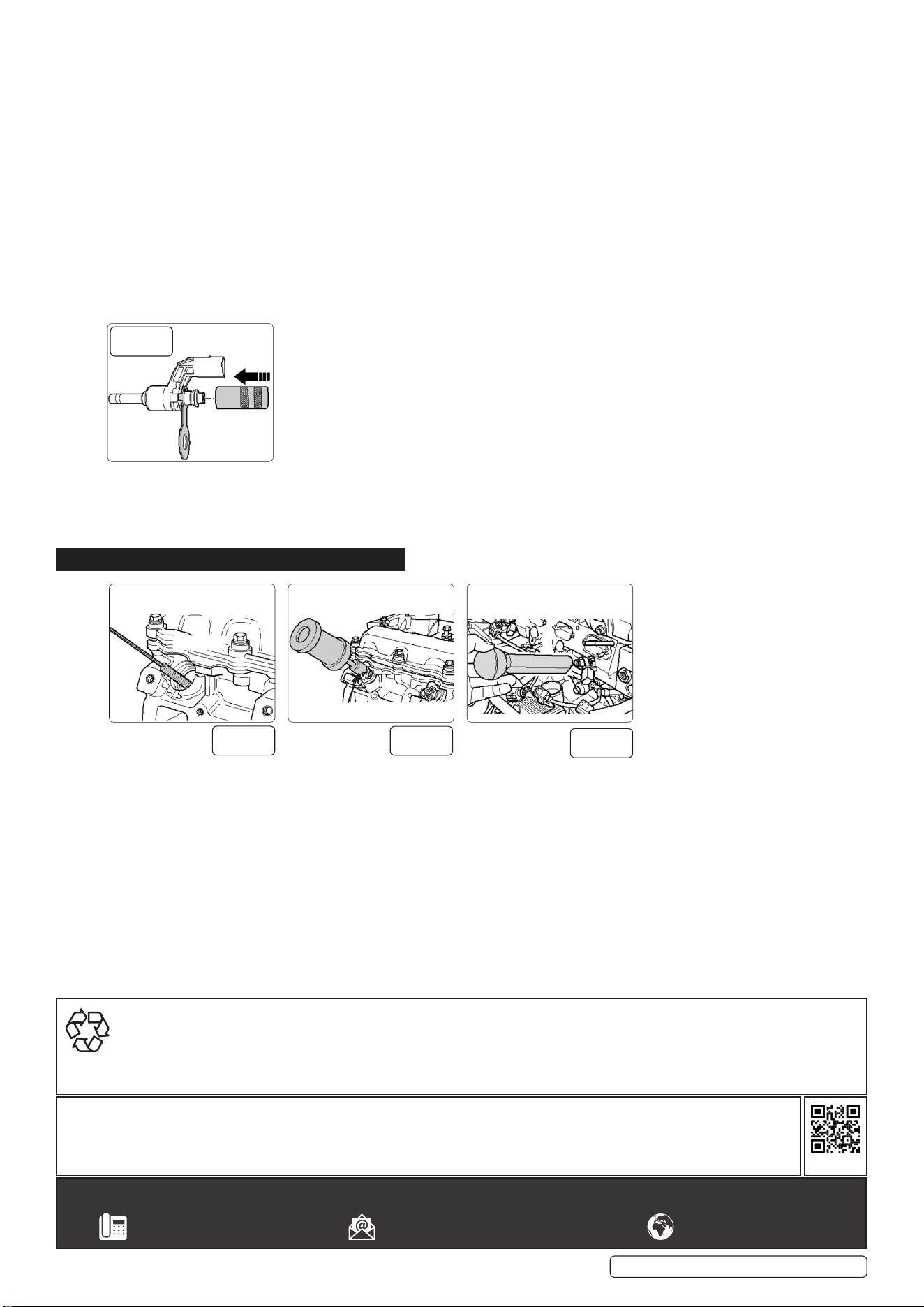
8.3.8. Stage 2 - Using VS2083.08 Calibration Sleeve (No.3), slide the Sleeve over the injector shaft whilst simultaneously rotating it 180°,
inserting it as far as it will go applying moderate force only. Then pull the Sleeve back, again rotating it 180° (g.12).
8.3.9. Some engine applications use the VS2083.11 Spacer Sleeve in conjunction with the VS2083.07 and VS2083.08 Calibration Sleeves
during the teon ring compression stages - Example 1.4FSi and 3.6 V6 FSi Engines (g.13).Seal Replacement Tools - Spacer Ring and
‘O’ Ring (fuel rail seal).
8.3.10. Replacement of the Spacer Ring and ‘O’ Ring are very straightforward on many injectors.
Original Language Version
© Jack Sealey Limited
VS2083 Issue 1 14/01/2025
3.2
3.1
fig.
6
fig.
7
fig.
8
21
16
fig.
9
16
21
fig.
10
17
fig.
11
18
fig.
12
fig.
13
fig.
14
14
fig.
15
NOTE: Apply a thin coating of clean engine oil on the new fuel rail ‘O’ Ring prior to installing it on to the injector.
8.3.11. Some injectors have a retaining spring and special tools from the VS2083 Kit (as listed below) are required to t the support ring to the
correct depth - Example 3.6 V6 FSi engines (g.14).
a) VS2083.12 Locking Plate.
b) VS2083.13 Assembly Cone.
c) VS2083.14 Calibration Sleeve (Single Knurl).
d) VS2083.17 Calibration Sleeve (Double Knurl).
8.3.12. Fit Locking Plate VS2083.12 in place of the retaining spring. Push the new support ring on to VS2083.13. Assembly Cone and t the
Assembly Cone onto the injector. Using VS2083.14 (with the knurled end facing the support ring) push the ring into the rst groove
(g.15).
8.4. REMOVE THE ASSEMBLY CONE.
8.4.1. Remove and turn around the Calibration Sleeve (knurled
end facing away from the support ring) and push the support ring until it contacts the VS2083.12 Locking Plate (g.16).
8.4.2. Remove the Calibration Sleeve and Locking Plate.
NOTE: Always use a new retaining spring if injectors are removed.
8.4.3. Fit the retaining spring, apply clean engine oil to the new ‘O’ Ring (fuel rail seal) and t against the support ring.
8.4.4. Some injectors require the use of VS2083.17 Calibration Sleeve in place of the VS2083.14 Sleeve to set the support ring to the correct
installation depth - Example 1.4FSi engines (g.17).
NOTE: Always ensure you consult the workshop instructions for the specic engine being worked on, to identify the appropriate tools
required.
9. INJECTOR INSTALLATION
9.1. INSTALLING INJECTORS
9.1.1. Initially install injectors by hand into the cylinder head. DO NOT use grease or oil and ensure there is no cleaning or lubrication uid in
the bores.
9.1.2. Ensure that the injectors are seated properly and if necessary use VS2083.09 Installer (g.20).
IMPORTANT! It is vital to ensure that the ridge in the base of the electrical connector seats into the cut-out in the cylinder head. It
should not be possible to rotate the injectors more than 5° if they are seated correctly.
13 or 14
fig.
16
19
© Jack Sealey Limited
Original Language Version
VS2083 Issue 1 14/01/2025
fig.
17
12
fig.
18
2-1
10-1,2,3
fig.
19
1
Sealey Group, Kempson Way, Suffolk Business Park, Bury St Edmunds, Suffolk. IP32 7AR
01284 757500 sales@sealey.co.uk www.sealey.co.uk
Note: It is our policy to continually improve products and as such we reserve the right to alter data, specifications and component parts
without prior notice.
Important: No Liability is accepted for incorrect use of this product.
Warranty: Guarantee is 12 months from purchase date, proof of which is required for any claim.
REGISTER YOUR
PURCHASE HERE
ENVIRONMENT PROTECTION
Recycle unwanted materials instead of disposing of them as waste. All tools, accessories and packaging should be sorted, taken to
a recycling centre and disposed of in a manner which is compatible with the environment. When the product becomes completely
unserviceable and requires disposal, drain any fluids (if applicable) into approved containers and dispose of the product and fluids
according to local regulations.
