DIGITAL FUEL PRESSURE TEST KIT – GDI -
6PC
Thank you for purchasing a Sealey product. Manufactured to a high standard, this product will, if used according to these
instructions, and properly maintained, give you years of trouble free performance.
IMPORTANT: PLEASE READ THESE INSTRUCTIONS CAREFULLY. NOTE THE SAFE OPERATIONAL REQUIREMENTS, WARNINGS & CAUTIONS. USE
THE PRODUCT CORRECTLY AND WITH CARE FOR THE PURPOSE FOR WHICH IT IS INTENDED. FAILURE TO DO SO MAY CAUSE DAMAGE AND/OR
PERSONAL INJURY AND WILL INVALIDATE THE WARRANTY. KEEP THESE INSTRUCTIONS SAFE FOR FUTURE USE.
1. SAFETY
WARNING! Ensure Health & Safety, local authority and general workshop practice regulations are adhered to when using this equipment.
8 DO NOT use tools if seals or threads are damaged. Any defective seal MUST be changed before use to avoid incorrect readings.
9 Maintain tools in good and clean condition for best and safest performance.
9 Ensure that a vehicle which has been jacked up is adequately supported with axle stands.
9 Wear approved eye protection. A full range of personal safety equipment is available from your Sealey stockist.
9 Wear suitable clothing to avoid snagging. DO NOT wear jewellery and tie back long hair.
9 Ensure any disconnected fuel pipes are plugged to avoid spillage.
9 Ensure that the correct connector is used for the engine being tested.
WARNING! Always release the pressure from the gauge before disconnecting the coupling.
9 Account for all tools, and parts being used and DO NOT leave them in or near the engine.
IMPORTANT: Always refer to the vehicle manufacturer’s service instructions, or a proprietary manual, to establish the current procedure
and data.
WARNING: The warnings, cautions and instructions discussed in this instruction manual cannot cover all possible conditions and
situations that may occur. It must be understood that common sense and caution are factors which cannot be built into this product, but
must be applied by the operator.
2. INTRODUCTION
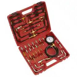
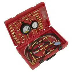
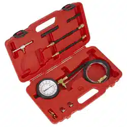
Real-time minimum and maximum fuel pressure values on GDI fuel circuits . Easy-to-read digital display. 2.8” backlit display. Pressure
units - psi, bar, kg/cm². Auto-power-o. Warning alarm if pressure exceeds 5148psi(355 bar). The set includes fuel hoses x2, T-piece,
fuel line adaptors x2. Supplied in storage case.
3. SPECIFICATION
4. FEATURES
VS566 Issue 4 11/03/25
Original Language Version
© Jack Sealey Limited
Refer to
instructions
MODEL NO: VS566
Wear eye
protection
Model No: VS566
Nett Weight: 1.5kg
Operating Temperature: -10 to 60°C
Operating Voltage: 6V
Pressure units: PSI, bar, kg/cm²
Accuracy: 1% FS
Range: 0 to 5221psi (0 to 360bar)
Resolution: 0.01bar, 0.01kg/cm², 0.01psi.
Battery: AAA x4 (not supplied)
Overload Pressure: 5801psi (400bar)
Hose Length: 550mm x2
Adaptors: M14x1.5/M15x1.0mm. M15x1.0/M14x1.5mm, T-Piece.
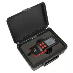
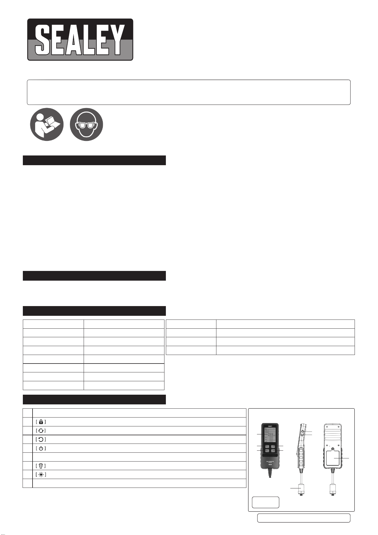
A Display
B Press to lock/unlock the interface
C Pressure units convert
D Press to reset testing time; D Long press to zero pressure
E Press to switch between Chinese/English mode; Long press to turn the device on/o
F Measuring Probe
G Press to turn on/o the key tone
H Press to turn on/o the backlight
I Battery Cover
A
B
D
g.A
C
E
F
G
H
I
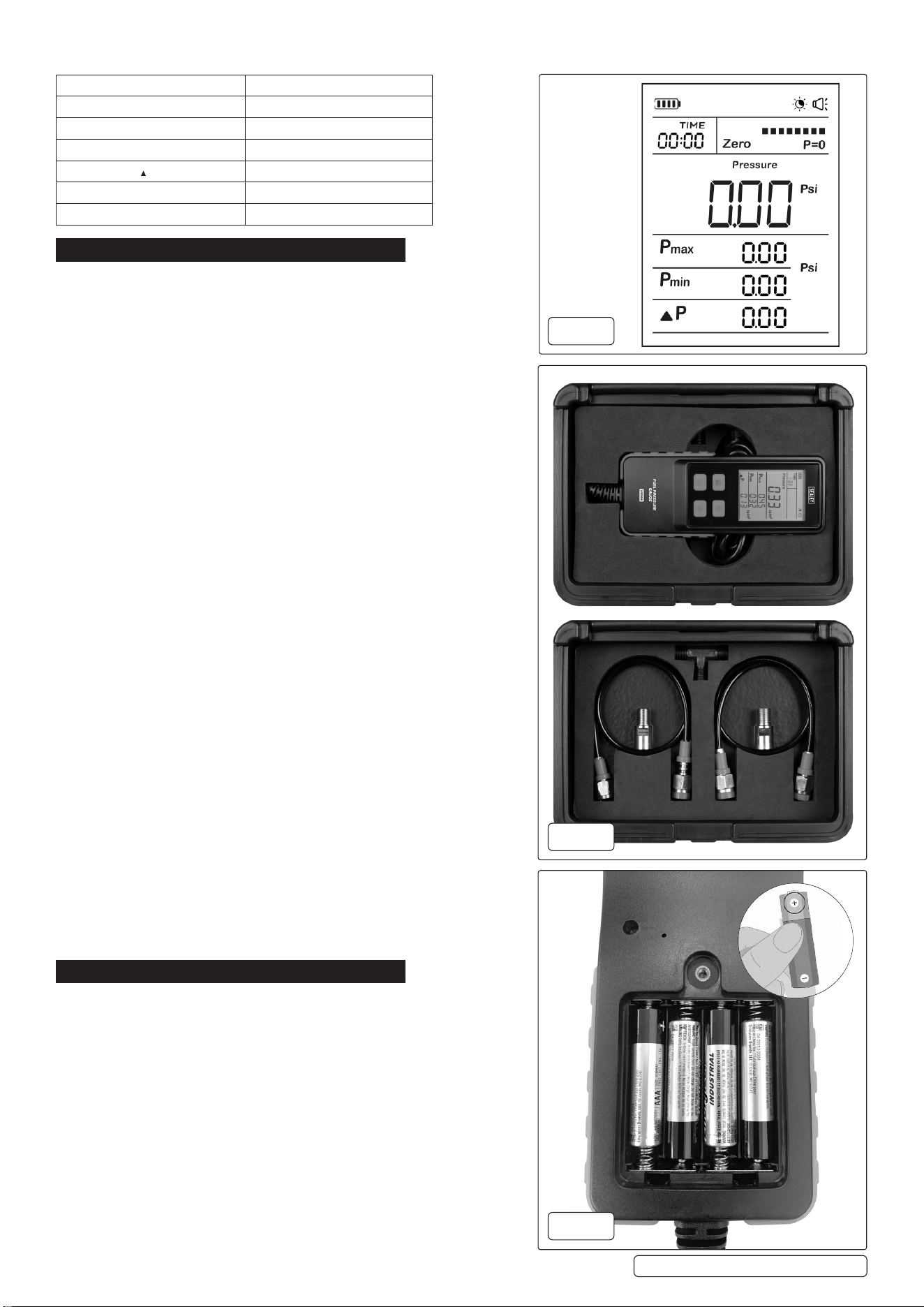
4.1. INTERFACE DISPLAY
5. OPERATION
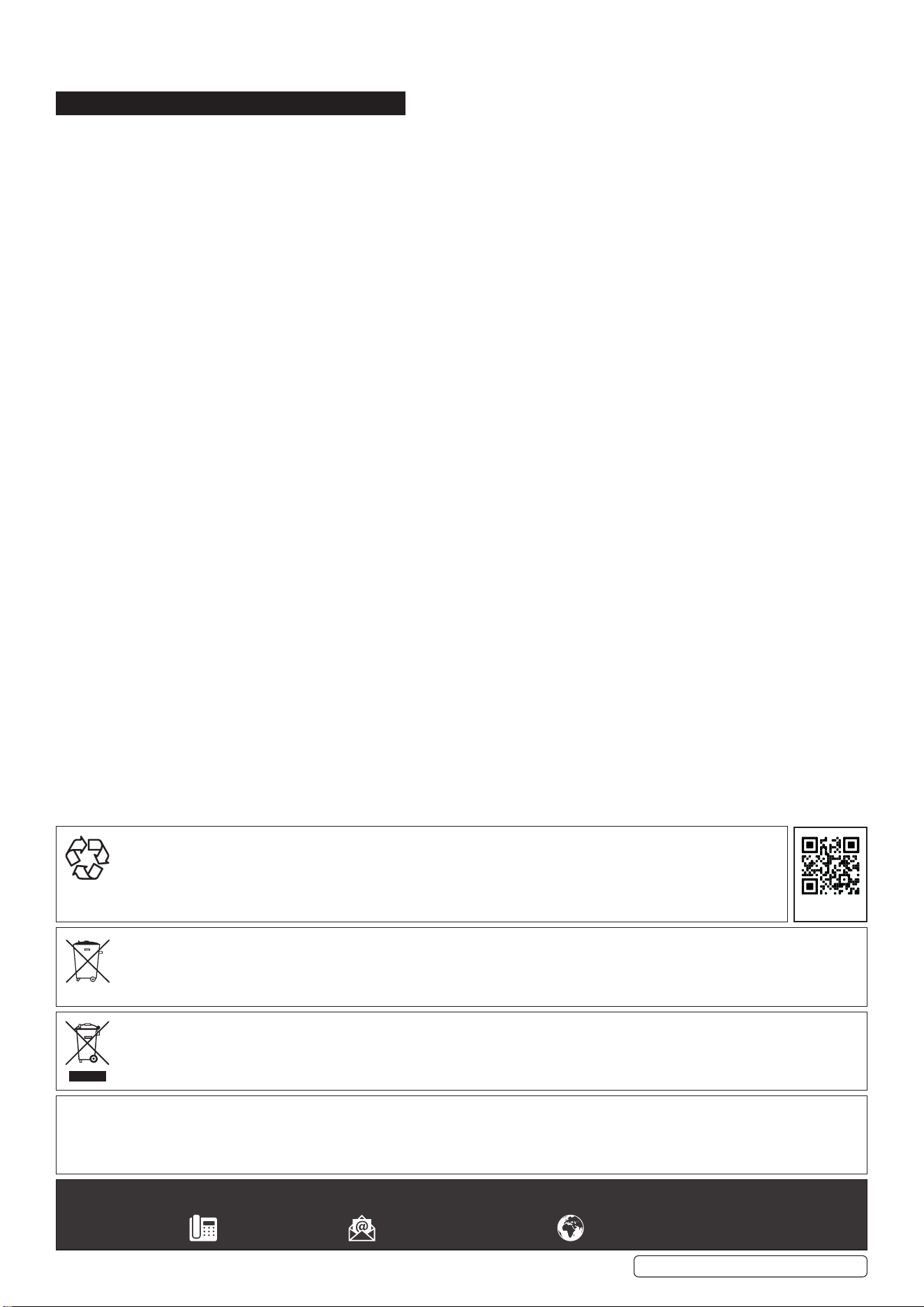
5.1. BATTERY INSTALLATION
5.1.1. Open the battery cover on the back of the device. Fig.3
5.1.2. Insert the batteries (4x1.5V AAA batteries), paying attention to the
correct polarity. See g.3
5.1.3. Close the battery cover securely.
5.2. RELEASE FUEL PRESSURE
5.2.1. First, unplug the fuel pump fuse, relay, or oil pump plug. Start the engine
until it turns o on its own. Start the engine 2-3 more times, then remove
the negative terminal of the battery.
5.3. INSTALL THE PRESSURE TESTER
5.3.1. Select the adapter suitable for the vehicle model (see g.2), connect it to
the measuring probe, then connect it to the direct injection fuel pipeline
of the engine. When removing the fuel pipe, place a towel or cotton cloth
under the fuel pipe interface to prevent fuel from leaking onto the ground.
5.4. OPERATIONS
5.4.1. Press (E) button for more than 2 seconds to start the instrument. (Fig A)
5.4.2. Press (D) button for pressure zero setting (real-time pressure display as
“0”). (Fig A).
5.4.3. Select the connector suitable for the vehicle model and connect it with
the hardware cable.
5.4.4. Connect with the direct fuel injection pipeline of the engine.
5.4.5. Press (D) button to clear the data and timing. (Fig A).
5.4.6. PRESSURE UNIT SELECTION: Press (C) button to select pressure
units. (Fig A).
5.5. START MEASURING
5.5.1. The direct injection fuel pressure gauge will display the pressure
measurement.
Detailed instructions are as follows if you need to lock and clear data on
the interface:
5.6. DATA LOCK AND INTERFACE LOCK
5.6.1. Press (B) button, and it will display data, interface, sound backlight, and
lock at the same time, and the interface will appear “lock” icon. (Fig A).
5.7. UNLOCK
5.7.1. Based on the last step, press the (B) button again, the device will display
data, interface, sound and backlight and is unlocked.
5.8. CLEAR THE DATA
5.8.1. Press (D) button, the data will clear completely. (Fig A).
5.8.2. After the measurement is completed, press (E) for 2 seconds to shut
down. (Fig A).
5.8.3. When the pressure exceeds 355bar, an alarm will sound as a warning.
5.8.4. The device will automatically power o after 5 minutes of inactivity and
no pressure being applied to the buttons.
6. MAINTENANCE
6.1. GENERAL
To maintain the performance and appearance of the product, it is
recommended that the following product care guidelines be read
carefully:
6.1.1. Regularly check the product parts that need to be tightened and
connected.
If found loose, tighten to ensure the safe operation of the equipment.
6.1.2. The external and internal parts of the equipment in contact with various
chemicals should be frequently treated with anti-corrosion treatment
such as rust removal.
6.1.3. Comply with the safe operating procedures and DO NOT overload the
equipment.
VS566 Issue 4 11/03/25
Original Language Version
© Jack Sealey Limited
Interface Display (g.1) Meaning
Pressure Current pressure
P max Current maximum pressure
P min Current minimum pressure
P Dierential
TIME Current measurement time
Bar, Kg/cm², Psi Pressure units
g.3
g.2
g.1
6.2. STORAGE
6.2.1. When not in use, please store the product in a dry childproof place. DO NOT store the product in hot, humid, or non-ventilated places.
7. END OF LIFE
7.1. Through years of normal wear, the fuel pressure digital gauge will eventually become unserviceable. When this happens ensure that it
is disposed of in accordance with local authority regulations.
7.2. BATTERY DISPOSAL
7.3. Exposure to high temperatures can cause the batteries to explode; DO NOT dispose of in a re. Some countries have regulations
concerning battery disposal. Follow all applicable regulations. Return used batteries to a collection location for recycling.
VS566 Issue 4 11/03/25
Original Language Version
© Jack Sealey Limited
Sealey Group, Kempson Way, Suffolk Business Park, Bury St Edmunds, Suffolk. IP32 7AR
01284 757500 sales@sealey.co.uk www.sealey.co.uk
Note: It is our policy to continually improve products and as such we reserve the right to alter data, specifications and component parts without prior
notice.
Important: No Liability is accepted for incorrect use of this product.
Warranty: Guarantee is 12 months from purchase date, proof of which is required for any claim.
WEEE REGULATIONS
Dispose of this product at the end of its working life in compliance with the EU Directive on Waste Electrical and Electronic Equipment
(WEEE). When the product is no longer required, it must be disposed of in an environmentally protective way. Contact your local solid
waste authority for recycling information.
BATTERY REMOVAL
Under the Waste Batteries and Accumulators Regulations 2009, Jack Sealey Ltd are required to inform potential purchasers of products
containing batteries (as defined within these regulations), that they are registered with Valpak’s registered compliance scheme. Jack
Sealey Ltd’s Batteries Producer Registration Number (BPRN) is BPRN00705.
ENVIRONMENT PROTECTION
Recycle unwanted materials instead of disposing of them as waste. All tools, accessories and packaging should be sorted,
taken to a recycling centre and disposed of in a manner which is compatible with the environment. When the product
becomes completely unserviceable and requires disposal, drain any fluids (if applicable) into approved containers and
dispose of the product and fluids according to local regulations.
REGISTER YOUR
PURCHASE HERE