Quick Start Guide
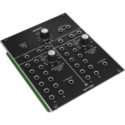
961 INTERFACE
Legendary Analog Multi-Channel Trigger Converter Module for Eurorack
V 2.0
2 3Quick Start Guide961 INTERFACE
(EN) Safety Instruction
1. Please read and follow all
instructions.
2. Keep the apparatus away from
water, except for outdoor products..
3. Clean only with a dry cloth.
4. Do not block any ventilation
openings. Install in accordance with the
manufacturer’s instructions.
5. Do not install near any heat
sources such as radiators, heat
registers, stoves or other apparatus
(including amplifiers) that
produce heat.
6. Use only attachments/accessories
specified by the manufacturer.
7. Use only
specified carts,
stands, tripods,
brackets, or tables.
Use caution to
prevent tip-over
when moving the cart/apparatus
combination.
8. Avoid installing in confined spaces
like bookcases.
9. Do not place near naked flame
sources, such as lighted candles.
10. Operating temperature range 5°
to 45°C (41° to 113°F).
LEGAL DISCLAIMER
Music Tribe accepts no liability for
any loss which may be suffered by
any person who relies either wholly
or in part upon any description,
photograph, or statement contained
herein. Technical specifications,
appearances and other information
are subject to change without notice.
All trademarks are the property
of their respective owners. Midas,
Klark Teknik, Lab Gruppen, Lake,
Tannoy, Turbosound, TC Electronic,
TC Helicon, Behringer, Bugera, Aston
Microphones and Coolaudio are
trademarks or registered trademarks
of Music Tribe Global Brands Ltd.
© Music Tribe Global Brands Ltd.
2024 All rights reserved.
LIMITED WARRANTY
For the applicable warranty terms
and conditions and additional
information regarding Music Tribe’s
Limited Warranty, please see
complete details online at community.
musictribe.com/support.
(ES)
Instrucción de seguridad
1. Por favor, lea y siga todas las
instrucciones.
2. Mantenga el aparato alejado
del agua, excepto para productos
destinados al uso en exteriores.
3. Limpie solo con un paño seco.
4. No bloquee ninguna abertura de
ventilación. Instale de acuerdo con las
instrucciones del fabricante.
5. No instale cerca de fuentes de
calor como radiadores, registros
de calor, estufas u otros aparatos
(incluyendo amplificadores) que
generen calor.
6. Utilice solo accesorios
especificados por el fabricante.
7. Use solo
carros, soportes,
trípodes, soportes
o mesas
especificados.
Tenga precaución
para evitar el vuelco al mover la
combinación carro/aparato.
8. Evite la instalación en espacios
confinados como estanterías.
9. No colocar cerca de fuentes de
llama desnuda, como velas encendidas.
10. Rango de temperatura de
funcionamiento de 5° a 45° C
(41° a 113° F).
NEGACIÓN LEGAL
Music Tribe no admite ningún tipo
de responsabilidad por cualquier
daño o pérdida que pudiera sufrir
cualquier persona por confiar total
o parcialmente en la descripciones,
fotografías o afirmaciones
contenidas en este documento.
Las especificaciones técnicas,
imágenes y otras informaciones
contenidas en este documento están
sujetas a modificaciones sin previo
aviso. Todas las marcas comerciales
que aparecen aquí son propiedad
de sus respectivos dueños. Midas,
Klark Teknik, Lab Gruppen, Lake,
Tannoy, Turbosound, TC Electronic,
TC Helicon, Behringer, Bugera, Aston
Microphones y Coolaudio son marcas
comerciales o marcas registradas
de Music Tribe Global Brands Ltd.
© Music Tribe Global Brands Ltd.
2024 Reservados todos los derechos.
GARANTÍA LIMITADA
Si quiere conocer los detalles y
condiciones aplicables de la garantía
así como información adicional sobre
la Garantía limitada de Music Tribe,
consulte online toda la información
en la web community.musictribe.
com/support.
(FR) Consignes de sécurité
1. Veuillez lire et suivre toutes les
instructions.
2. Gardez l'appareil éloigné de l'eau,
sauf pour les produits destinés à une
utilisation en extérieur.
3. Nettoyez uniquement avec un
chiffon sec.
4. Ne bloquez aucune ouverture de
ventilation. Installez conformément
aux instructions du fabricant.
5. N'installez pas près de sources de
chaleur telles que radiateurs, grilles de
chaleur, cuisinières ou autres appareils
(y compris les amplificateurs) qui
produisent de la chaleur.
6. Utilisez uniquement les
accessoires spécifiés par le fabricant.
7. Utilisez
uniquement des
chariots, des
supports, des
trépieds, des
supports ou des
tables spécifiés. Faites attention pour
éviter le renversement lors du
déplacement de la combinaison
chariot/appareil.
8. Évitez l'installation dans
des espaces confinés comme les
bibliothèques.
9. Ne pas placer près de sources
de flamme nue, telles que des
bougies allumées.
10. Plage de température de
fonctionnement de 5° à 45° C
(41° à 113)
DÉNI LÉGAL
Music Tribe ne peut être tenu pour
responsable pour toute perte pouvant
être subie par toute personne se
fiant en partie ou en totalité à
toute description, photographie
ou affirmation contenue dans ce
document. Les caractéristiques,
l’apparence et d’autres informations
peuvent faire l’objet de modifications
sans notification. Toutes les marques
appartiennent à leurs propriétaires
respectifs. Midas, Klark Teknik,
Lab Gruppen, Lake, Tannoy,
Turbosound, TC Electronic, TC Helicon,
Behringer, Bugera, Aston Microphones
et Coolaudio sont des marques ou
marques déposées de Music Tribe
Global Brands Ltd. © Music Tribe Global
Brands Ltd. 2024 Tous droits réservés.
GARANTIE LIMITÉE
Pour connaître les termes et conditions
de garantie applicables, ainsi que
les informations supplémentaires et
détaillées sur la Garantie Limitée de
Music Tribe, consultez le site Internet
community.musictribe.com/support.
(DE) Wichtige
Sicherheitshinweise
1. Bitte lesen Sie alle Anweisungen
sorgfältig durch und befolgen
Sie diese.
2. Halten Sie das Gerät von Wasser
fern, außer für Produkte, die für den
Außeneinsatz vorgesehen sind.
3. Reinigen Sie es nur mit einem
trockenen Tuch.
4. Blockieren Sie keine
Belüftungsöffnungen. Installieren
Sie gemäß den Anweisungen
des Herstellers.
5. Installieren Sie nicht in der Nähe
von Wärmequellen wie Heizkörpern,
Heizregistern, Öfen oder anderen
Geräten (einschließlich Verstärkern),
die Wärme erzeugen.
6. Verwenden Sie nur Zubehörteile,
die vom Hersteller angegeben sind.
7. Verwenden
Sie nur
spezifizierte
Wagen, Ständer,
Stative,
Halterungen oder
Tische. Achten Sie darauf, beim
Bewegen der Wagen-Geräte-
Kombination ein Umkippen
zu vermeiden.
8. Vermeiden Sie die Installation in
beengten Räumen wie Bücherregalen.
9. Nicht in der Nähe von offenen
Flammenquellen platzieren,
wie brennende Kerzen.
10. Betriebstemperaturbereich von 5°
bis 45°C (41° bis 113°F).
HAFTUNGSAUSSCHLUSS
Music Tribe übernimmt keine Haftung
für Verluste, die Personen entstanden
sind, die sich ganz oder teilweise auf
hier enthaltene Beschreibungen,
Fotos oder Aussagen verlassen haben.
Technische Daten, Erscheinungsbild
und andere Informationen können
ohne vorherige Ankündigung
geändert werden. Alle Warenzeichen
sind Eigentum der jeweiligen
Inhaber. Midas, Klark Teknik, Lab
Gruppen, Lake, Tannoy, Turbosound,
TC Electronic, TC Helicon, Behringer,
Bugera, Aston Microphones und
Coolaudio sind Warenzeichen oder
eingetragene Warenzeichen der
Music Tribe Global Brands Ltd.
© Music Tribe Global Brands Ltd.
2024 Alle Rechte vorbehalten.
BESCHRÄNKTE GARANTIE
Die geltenden Garantiebedingungen
und zusätzliche Informationen
bezüglich der von Music Tribe
gewährten beschränkten Garantie
finden Sie online unter community.
musictribe.com/support.
(PT) Instruções de
Seguranç Importantes
1. Por favor, leia e siga todas as
instruções.
2. Mantenha o aparelho longe da
água, exceto para produtos destinados
ao uso externo.
3. Limpe apenas com um pano seco.
4. Não bloqueie nenhuma abertura
de ventilação. Instale de acordo com as
instruções do fabricante.
5. Não instale próximo a fontes
de calor, como radiadores, grelhas
de calor, fogões ou outros aparelhos
(incluindo amplificadores) que
gerem calor.
6. Use apenas acessórios
especificados pelo fabricante.
7. Use apenas
carrinhos,
suportes, tripés,
suportes ou mesas
especificados.
Tenha cuidado
para evitar tombamentos ao mover a
combinação carrinho/aparelho.
8. Evite instalar em espaços
confinados, como estantes.
9. Não coloque perto de fontes de
chama nua, como velas acesas.
10. Intervalo de temperatura de
operação de 5° a 45° C (41° a 113° F).
LEGAL RENUNCIANTE
O Music Tribe não se responsabiliza
por perda alguma que possa ser
sofrida por qualquer pessoa que
dependa, seja de maneira completa
ou parcial, de qualquer descrição,
fotografia, ou declaração aqui
contidas. Dados técnicos, aparências
e outras informações estão sujeitas
a modificações sem aviso prévio.
Todas as marcas são propriedade
de seus respectivos donos. Midas,
Klark Teknik, Lab Gruppen, Lake,
Tannoy, Turbosound, TC Electronic,
4 5Quick Start Guide961 INTERFACE
TC Helicon, Behringer, Bugera,
Aston Microphones e Coolaudio
são marcas ou marcas registradas
do Music Tribe Global Brands Ltd.
© Music Tribe Global Brands Ltd.
2024 Todos direitos reservados.
GARANTIA LIMITADA
Para obter os termos de garantia
aplicáveis e condições e informações
adicionais a respeito da garantia
limitada do Music Tribe, favor verificar
detalhes na íntegra através do website
community.musictribe.com/support.
(IT) Istruzioni di sicurezza
importanti
1. Per favore, leggere e seguire tutte
le istruzioni.
2. Mantenere l'apparecchio lontano
dall'acqua, tranne per i prodotti
destinati all'uso all'aperto.
3. Pulire solo con un panno asciutto.
4. Non ostruire alcuna apertura di
ventilazione. Installare in conformità
alle istruzioni del produttore.
5. Non installare vicino a fonti di
calore come termosifoni, bocchette
di calore, fornelli o altri apparecchi
(compresi gli amplificatori) che
producono calore.
6. Utilizzare solo accessori specificati
dal produttore.
7. Usare solo
carrelli, supporti,
treppiedi, staffe o
tavoli specificati.
Prestare
attenzione per
evitare il ribaltamento durante lo
spostamento della combinazione
carrello/apparecchio.
8. Evitare l'installazione in spazi
confinati come librerie.
9. Non posizionare vicino a fonti di
fiamma nude, come candele accese.
10. Intervallo di temperatura
di funzionamento da 5° a 45° C
(41° a 113° F)
DISCLAIMER LEGALE
Music Tribe non si assume alcuna
responsabilità per eventuali danni che
possono essere subiti da chiunque si
affidi in tutto o in parte a qualsiasi
descrizione, fotografia o dichiarazione
contenuta qui. Specifiche tecniche,
aspetti e altre informazioni sono
soggette a modifiche senza preavviso.
Tutti i marchi sono di proprietà
dei rispettivi titolari. Midas, Klark
Teknik, Lab Gruppen, Lake, Tannoy,
Turbosound, TC Electronic, TC Helicon,
Behringer, Bugera, Aston Microphones
e Coolaudio sono marchi o marchi
registrati di Music Tribe Global Brands
Ltd. © Music Tribe Global Brands Ltd.
2024 Tutti i diritti riservati.
GARANZIA LIMITATA
Per i termini e le condizioni di garanzia
applicabili e le informazioni aggiuntive
relative alla garanzia limitata di Music
Tribe, consultare online i dettagli
completi su community.musictribe.
com/support.
(NL) Belangrijke
veiligheidsvoorschriften
1. Lees alsjeblieft alle instructies en
volg deze op.
2. Houd het apparaat uit de buurt
van water, behalve voor producten die
bedoeld zijn voor buitengebruik.
3. Reinig alleen met een droge doek.
4. Blokker geen ventilatieopeningen.
Installeer volgens de instructies van de
fabrikant.
5. Installeer niet in de buurt van
warmtebronnen zoals radiatoren,
warmte registers, fornuizen of andere
apparaten (inclusief versterkers) die
warmte produceren.
6. Gebruik alleen accessoires die
door de fabrikant zijn gespecificeerd.
7. Gebruik
alleen
gespecificeerde
karren, standaards,
statieven, beugels
of tafels. Wees
voorzichtig om kantelen te voorkomen
bij het verplaatsen van de kar/
apparaatcombinatie.
8. Vermijd installatie in afgesloten
ruimtes zoals boekenkasten.
9. Plaats niet in de buurt
van naakte vlambronnen,
zoals brandende kaarsen.
10. Bedrijfstemperatuurbereik van 5°
tot 45°C (41° tot 113°F).
WETTELIJKE ONTKENNING
Music Tribe aanvaardt geen
aansprakelijkheid voor enig verlies
dat kan worden geleden door een
persoon die geheel of gedeeltelijk
vertrouwt op enige beschrijving,
foto of verklaring hierin. Technische
specificaties, verschijningen en andere
informatie kunnen zonder voorafgaande
kennisgeving worden gewijzigd. Alle
handelsmerken zijn eigendom van hun
respectievelijke eigenaren. Midas, Klark
Teknik, Lab Gruppen, Lake, Tannoy,
Turbosound, TC Electronic, TC Helicon,
Behringer, Bugera, Aston Microphones
en Coolaudio zijn handelsmerken of
gedeponeerde handelsmerken van
Music Tribe Global Brands Ltd. © Music
Tribe Global Brands Ltd. 2024 Alle
rechten voorbehouden.
BEPERKTE GARANTIE
Voor de toepasselijke
garantievoorwaarden en aanvullende
informatie met betrekking tot de
beperkte garantie van Music Tribe,
zie de volledige details online op
community.musictribe.com/support.
(SE) Viktiga
säkerhetsanvisningar
1. Vänligen läs och följ alla
instruktioner noggrant.
2. Håll apparaten borta från vatten,
förutom för utomhusprodukter.
3. Rengör endast med en torr trasa.
4. Blockera inte några
ventilationsöppningar. Installera enligt
tillverkarens anvisningar.
5. Installera inte nära några
värmekällor som element,
värmeregistrar, spisar eller andra
apparater (inklusive förstärkare) som
genererar värme.
6. Använd endast tillbehör som
anges av tillverkaren.
7. Använd
endast
specificerade
vagnar, ställ, stativ,
fästen eller bord.
Var försiktig för att
undvika att vagnen/
apparatkombinationen tippar när
den flyttas.
8. Undvik installation i trånga
utrymmen som bokhyllor.
9. Placera inte nära öppen låga,
såsom tända ljus.
10. Driftstemperaturområde 5° till
45° C (41° till 113° F).
FRISKRIVNINGSKLAUSUL
Music Tribe tar inget ansvar för
någon förlust som kan drabbas av
någon person som helt eller delvis
förlitar sig på någon beskrivning,
fotografi eller uttalande som finns här.
Tekniska specifikationer, utseenden
och annan information kan ändras
utan föregående meddelande. Alla
varumärken tillhör respektive ägare.
Midas, Klark Teknik, Lab Gruppen, Lake,
Tannoy, Turbosound, TC Electronic,
TC Helicon, Behringer, Bugera,
Aston Microphones och Coolaudio
är varumärken eller registrerade
varumärken som tillhör Music Tribe Global
Brands Ltd. © Music Tribe Global Brands
Ltd. 2024 Alla Rättigheter reserverade.
BEGRÄNSAD GARANTI
För tillämpliga garantivillkor och
ytterligare information om Music Tribes
begränsade garanti, se fullständig
information online på community.
musictribe.com/support.
(PL) Ważne informacje o
bezpieczeństwie
1. Proszę przeczytać i ścisłe
przestrzegać wszystkich instrukcji.
2. Trzymaj urządzenie z dala
od wody, z wyjątkiem produktów
przeznaczonych do użytku na
zewnątrz.
3. Czyść tylko suchą szmatką.
4. Nie blokuj żadnych otworów
wentylacyjnych. Instaluj zgodnie z
instrukcjami producenta.
5. Nie instaluj w pobliżu źródeł
ciepła, takich jak grzejniki, rejestratory
ciepła, kuchenki lub inne urządzenia
(w tym wzmacniacze), które generują
ciepło.
6. Używaj tylko akcesoriów
określonych przez producenta.
7. Używaj tylko
określonych
wózków, stojaków,
statywów,
uchwytów lub
stołów. Uważaj,
aby zapobiec przewróceniu się wózka/
aparatu podczas przemieszczania.
8. Unikaj instalacji w ciasnych
miejscach, takich jak regały na książki.
9. Nie umieszczaj w pobliżu
źródeł otwartego ognia, takich jak
zapalone świeczki.
10. Zakres temperatury pracy od 5°
do 45°C (41° do 113°F).
ZASTRZEŻENIA PRAWNE
Music Tribe nie ponosi
odpowiedzialności za jakiekolwiek
straty, które mogą ponieść osoby,
które polegają w całości lub w
części na jakimkolwiek opisie,
fotografii lub oświadczeniu
zawartym w niniejszym dokumencie.
Specyfikacje techniczne, wygląd i
inne informacje mogą ulec zmianie
bez powiadomienia. Wszystkie
znaki towarowe są własnością ich
odpowiednich właścicieli. Midas,
Klark Teknik, Lab Gruppen, Lake,
Tannoy, Turbosound, TC Electronic,
TC Helicon, Behringer, Bugera, Aston
Microphones i Coolaudio są znakami
towarowymi lub zastrzeżonymi
znakami towarowymi firmy Music
Tribe Global Brands Ltd. © Music Tribe
Global Brands Ltd. 2024 Wszystkie
prawa zastrzeżone.
OGRANICZONA GWARANCJA
Aby zapoznać się z obowiązującymi
warunkami gwarancji i dodatkowymi
informacjami dotyczącymi
ograniczonej gwarancji Music Tribe,
zapoznaj się ze wszystkimi szczegółami
w trybie online pod adresem
community.musictribe.com/support.
(JP) 安全指示
1.
すべての指示を読んで、
従ってください。
2. 屋 外 の 製 品 を 除 き 、機 器
を水から遠ざけてください。
3. 乾 いた布 で のみ清 掃して
ください。
4. 通気口を塞がないでくだ
さ い 。メ ー カ ー の 指 示 に 従 っ
てインストールしてください 。
5. 暖 房 器 、ヒ ー ト レ ジ ス タ
ー 、ス ト ー ブ な ど の 発 熱 機 器
(アンプを含む)の近くには
取り付けないでください。
6. メーカーが指 定したアタ
ッチメント/アクセサリーのみ
使 用してください 。
7. 指定され
たカート、スタ
ン ド 、三 脚 、ブ
ラ ケ ッ ト 、ま た
はテ ーブル の
み 使 用してく
だ さ い 。カ ー ト / 機 器 の 組 み 合
わ せ を 移 動 す る 際 に は 、転 倒
を防ぐよう注 意してくだ
さい。
8. 書 棚などの密閉された
空間には設 置しないでくだ
さい。
9. 裸火のような火の元の近
くに置 かないでください 。
6 7Quick Start Guide961 INTERFACE
10. 動作温度範囲は摂氏 5
度から 45 度 (華氏 41 度から
113 度) です。
法的放棄
ここに含まれる記述、
写真、意見の全体または一
部に依拠して、いかなる人
が損害を生じさせた場合に
も、
MUSIC Tribe
は一切の賠償
責任を負いません。技術仕
様、外観およびその他の情報
は予告なく変更になる場合
があります。商標はすべて、
それぞれの所有者に帰属し
ます。
Midas
、
Klark Teknik
、
Lab Gruppen
、
Lake
、
Tannoy
、
Turbosound
、
TC Electronic
、
TC Helicon
、
Behringer
、
Bugera
、
Aston
Microphones
および
Coolaudio
は
Music Tribe Global Brands Ltd.
の商標
または登録商標です。
© Music
Tribe Global Brands Ltd. 2024
無断転
用禁止。
限定保証
適用される保証条件と
Music Tribe の限定保証に関
す る 概 要 に つ い て は 、オ ン
ライン上
community.musictribe.
com/support
にて詳 細をご確 認
ください。
(CN) 安全须知
1.
请阅读, 保存, 遵守所有
的说明, 注意所有的警示。
2. 请勿在靠近水的地方使用
本产品。
3. 请用干布清洁本产品。
4. 请只使用厂家指定的附属
设备和配件。 不要堵塞任何
通风口。按照制造商的说明进
行安装。
5. 请只使用厂
家指定的或随
货销售的手推
车, 架子, 三角
架, 支架和桌
子等。 若使用手推车来搬运设
备, 请注意安全放置设备, 以
避免手推车和设备倾倒而
受伤。
6. 请勿安装在密闭空间, 如书
柜或类似装置。
7. 请勿将本产品安装在热源
附近, 如暖气片, 炉子或其它产
生热量的设备 (包括功放器)
。 产品上不要放置裸露的火焰
源, 如点燃的蜡烛。
8. 如果液体流入或异物落入
设备内, 设备遭雨淋或受潮, 设
备不 能正常运作或被摔坏等,
设备受损需进行维修时, 所有
维修均须由 合格的维修人员
进行维修。
法律声明
对于任何因在此说明书提到
的全部或部份描述、 图片或
声明而造成的损失,
Music Tribe
不负任何责任。 技术参数和
外观若有更改, 恕不另行通
知。 所有的商标均为其各自所
有者的财产。
Midas, Klark Teknik,
Lab Gruppen, Lake, Tannoy,
Turbosound, TC Electronic, TC Helicon,
Behringer, Bugera, Aston Microphones
和 Coolaudio 是 Music Tribe Global
Brands Ltd.
公司的商标或注册
商标。
© Music Tribe Global Brands
Ltd. 2024
版权所有。
保修条款
有关音乐集团保修的适用条
款及其它相关信息, 请登陆
community.musictribe.com/support
网站查看完整的详细信息。
8 9Quick Start Guide961 INTERFACE
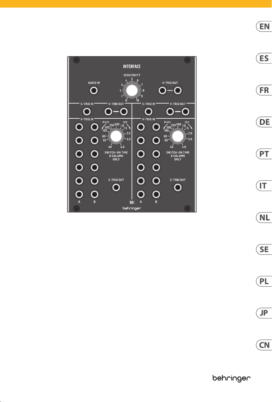
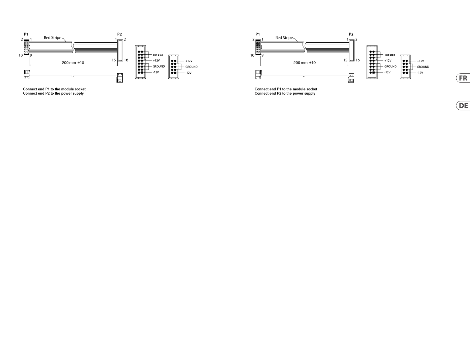
961 INTERFACE Controls
(EN)
Controls
(1) AUDIO IN – Use this 3.5 mm jack to route an audio
signal into the module for conversion to a V-Trig
(voltage trigger) signal. The audio signal passes
through the SENSITIVITY control before being
converted, and the final, converted signal then exits
the module at the V-TRIG OUT parallel connections
immediately to the right of the SENSITIVITY knob.
(2) SENSITIVITY – Use this knob to adjust the gain of
the audio signal coming into the module through
the AUDIO IN jack. Rotate the knob until you
find a setting that gives you the best audio-to-
voltage conversion.
(3) V-TRIG OUT – Use the parallel jacks to route the
converted audio-to-voltage V-Trig signal back out
of the module via cables with 3.5 mm TS connectors.
(4) S-TRIG IN – Route S-Trig (switch trigger) control
signals into the module via cables with 3.5 mm TS
connectors for conversion to V-Trig (voltage trigger)
signals. The converted V-Trig signal comes back
out of the module via the parallel V-TRIG OUT jacks
immediately to the right of the S-TRIG IN jack.
(5) V-TRIG OUT – Use these parallel jacks to send the
converted V-Trig signal back out of the module via
cables with 3.5 mm TS connectors.
(6) V-TRIG IN A/B – Use these rows of 3.5 mm jacks to
route in multiple V-Trig (voltage trigger) signals for
conversion to an S-Trig (switch trigger) signal that
exits the module via the S-TRIG OUT jack assigned
to this section of the module. The V-TRIG IN A row
of inputs go straight to conversion and output,
while the V-TRIG IN B row of inputs pass through the
SWITCH-ON TIME control before being combined
with the converted A signal for final output through
the S-TRIG OUT jack. When any valid V-TRIG input
activates the S-TRIG output, any other V-TRIG input
activity will be ignored until the first V-TRIG cycle
has ended.
(7) SWITCH-ON TIME – Use this knob to manually
limit or extend the “ON” time duration of V-Trig
signals coming in through the V-TRIG IN B row
of input jacks. The “ON” time can be varied from
40 milliseconds to a full 4 seconds.
(8) S-TRIG OUT – This jack routes the final S-Trig signal
from the V-TRIG IN A/B jacks back out of the module
via cables with 3.5 mm TS connectors.
(1) (2) (4)
(5)
(7)
(6)
(8)
(3)

10 11Quick Start Guide961 INTERFACE
(1) AUDIO IN – Utilisez cette prise jack 3,5 mm pour
acheminer un signal audio dans le module pour la
conversion en un signal V-Trig (déclenchement de
tension). Le signal audio passe par la commande
SENSITIVITY avant d’être converti, et le signal
converti final sort alors du module au niveau des
connexions parallèles V-TRIG OUT immédiatement à
droite du bouton SENSITIVITY.
(2) SENSITIVITY – Utilisez ce bouton pour régler le
gain du signal audio entrant dans le module via la
prise AUDIO IN. Tournez le bouton jusqu’à ce que
vous trouviez un réglage qui vous offre la meilleure
conversion audio-tension.
(3) V-TRIG OUT – Utilisez les prises parallèles pour
acheminer le signal V-Trig audio-tension converti
hors du module via des câbles avec des connecteurs
TS de 3,5 mm.
(4) S-TRIG IN – Acheminer les signaux de commande
S-Trig (déclenchement par interrupteur) dans le
module via des câbles avec connecteurs TS 3,5 mm
pour la conversion en signaux V-Trig (déclenchement
par tension). Le signal V-Trig converti sort du module
via les prises parallèles V-TRIG OUT immédiatement
à droite de la prise S-TRIG IN.
(5) V-TRIG OUT – Utilisez ces prises parallèles pour
renvoyer le signal V-Trig converti hors du module via
des câbles avec connecteurs TS 3,5 mm.
(6) V-TRIG IN A/B – Utilisez ces rangées de prises jack
3,5 mm pour acheminer plusieurs signaux V-Trig
(déclenchement de tension) pour la conversion en
un signal S-Trig (déclenchement par interrupteur)
qui sort du module via la prise S-TRIG OUT affectée à
cette section du module . La rangée d’entrées V-TRIG
IN A passe directement à la conversion et à la sortie,
tandis que la rangée d’entrées V-TRIG IN B passe
par la commande SWITCH-ON TIME avant d’être
combinée avec le signal converti A pour la sortie
finale via le S-TRIG Prise OUT. Lorsqu’une entrée
V-TRIG valide active la sortie S-TRIG, toute autre
activité d’entrée V-TRIG sera ignorée jusqu’à la fin
du premier cycle V-TRIG.
(7) SWITCH-ON TIME – Utilisez ce bouton pour limiter
ou prolonger manuellement la durée «ON» des
signaux V-Trig entrant via la rangée V-TRIG IN B de
prises d’entrée. Le temps «ON» peut varier de 40
millisecondes à 4 secondes complètes.
(8) S-TRIG OUT – Cette prise achemine le signal S-Trig
final des prises V-TRIG IN A / B hors du module via
des câbles avec connecteurs TS 3,5 mm.
(1) AUDIO IN – Utilice este conector de 3,5 mm
para enrutar una señal de audio al módulo para
convertirla en una señal V-Trig (disparador de
voltaje). La señal de audio pasa a través del control
SENSITIVITY antes de ser convertida, y la señal
convertida final sale del módulo por las conexiones
paralelas V-TRIG OUT inmediatamente a la derecha
de la perilla SENSITIVITY.
(2) SENSITIVITY – Utilice esta perilla para ajustar la
ganancia de la señal de audio que ingresa al módulo
a través del conector AUDIO IN. Gire la perilla hasta
que encuentre una configuración que le brinde la
mejor conversión de audio a voltaje.
(3) V-TRIG OUT – Utilice las tomas paralelas para
enrutar la señal V-Trig convertida de audio a voltaje
fuera del módulo a través de cables con conectores
TS de 3,5 mm.
(4) S-TRIG IN – Enrute las señales de control S-Trig
(disparador de interruptor) al módulo a través
de cables con conectores TS de 3,5 mm para
convertirlas en señales V-Trig (disparador de
voltaje). La señal V-Trig convertida vuelve a salir del
módulo a través de las tomas V-TRIG OUT paralelas
inmediatamente a la derecha de la toma S-TRIG IN.
(5) V-TRIG OUT – Utilice estas tomas paralelas para
enviar la señal V-Trig convertida fuera del módulo a
través de cables con conectores TS de 3,5 mm.
(6) V-TRIG IN A/B – Utilice estas filas de conectores
de 3,5 mm para enrutar múltiples señales V-Trig
(disparador de voltaje) para convertirlas en una
señal S-Trig (disparador de interruptor) que sale del
módulo a través del conector S-TRIG OUT asignado
a esta sección del módulo . La fila de entradas
V-TRIG IN A van directamente a conversión y salida,
mientras que la fila de entradas V-TRIG IN B pasa
a través del control SWITCH-ON TIME antes de
combinarse con la señal A convertida para la salida
final a través del S-TRIG OUT jack. Cuando cualquier
entrada V-TRIG válida activa la salida S-TRIG,
cualquier otra actividad de entrada V-TRIG será
ignorada hasta que finalice el primer ciclo V-TRIG.
(7) SWITCH-ON TIME – Use esta perilla para limitar o
extender manualmente la duración de tiempo de
“ON” de las señales V-Trig que ingresan a través de
la fila V-TRIG IN B de tomas de entrada. El tiempo de
“ENCENDIDO” se puede variar de 40 milisegundos a
4 segundos completos.
(8) S-TRIG OUT – Este conector enruta la señal S-Trig
final desde los conectores V-TRIG IN A / B hacia
afuera del módulo a través de cables con conectores
TS de 3,5 mm.
(FR) Réglages( ES) Controles
961 INTERFACE Controls

12 13Quick Start Guide961 INTERFACE
(1) AUDIO IN – Use este conector de 3,5 mm para
rotear um sinal de áudio no módulo para conversão
em um sinal V-Trig (acionamento de tensão). O
sinal de áudio passa pelo controle SENSITIVITY
antes de ser convertido e o sinal convertido final
sai do módulo nas conexões paralelas V-TRIG OUT
imediatamente à direita do botão SENSITIVITY.
(2) SENSITIVITY – Use este botão para ajustar o ganho
do sinal de áudio que chega ao módulo por meio do
conector AUDIO IN. Gire o botão até encontrar uma
configuração que forneça a melhor conversão de
áudio em voltagem.
(3) V-TRIG OUT – Use os conectores paralelos para
rotear o sinal V-Trig convertido de áudio para tensão
de volta para fora do módulo por meio de cabos com
conectores TS de 3,5 mm.
(4) S-TRIG IN – Encaminhe os sinais de controle S-Trig
(gatilho de chave) para o módulo por meio de
cabos com conectores TS de 3,5 mm para conversão
em sinais V-Trig (gatilho de tensão). O sinal V-Trig
convertido volta do módulo por meio dos conectores
V-TRIG OUT paralelos imediatamente à direita do
conector S-TRIG IN.
(5) V-TRIG OUT – Use esses conectores paralelos para
enviar o sinal V-Trig convertido de volta para fora
do módulo por meio de cabos com conectores TS de
3,5 mm.
(6) V-TRIG IN A / B – Use essas linhas de conectores de
3,5 mm para rotear vários sinais V-Trig (gatilho de
tensão) para conversão em um sinal S-Trig (gatilho
de chave) que sai do módulo através do conector
S-TRIG OUT atribuído a esta seção do módulo .
A linha de entradas V-TRIG IN A vai direto para a
conversão e saída, enquanto a linha de entradas
V-TRIG IN B passa pelo controle SWITCH-ON TIME
antes de ser combinada com o sinal A convertido
para a saída final através do S-TRIG Jack OUT.
Quando qualquer entrada V-TRIG válida ativa
a saída S-TRIG, qualquer outra atividade de
entrada V-TRIG será ignorada até que o primeiro
ciclo V-TRIG termine.
(7) SWITCH-ON TIME – Use este botão para limitar ou
estender manualmente a duração do tempo “ON”
dos sinais V-Trig que chegam através da linha V-TRIG
IN B de conectores de entrada. O tempo “ON” pode
variar de 40 milissegundos a 4 segundos completos.
(8) S-TRIG OUT – Este conector direciona o sinal S-Trig
final dos conectores V-TRIG IN A / B de volta para
fora do módulo por meio de cabos com conectores
TS de 3,5 mm.
(1) AUDIO IN – Verwenden Sie diese 3,5-mm-Buchse,
um ein Audiosignal zur Umwandlung in ein V-Trig-
Signal (Spannungsauslöser) in das Modul zu leiten.
Das Audiosignal durchläuft den SENSITIVITY-Regler,
bevor es konvertiert wird, und das endgültige
konvertierte Signal verlässt das Modul an den
parallelen V-TRIG OUT-Verbindungen unmittelbar
rechts vom SENSITIVITY-Regler.
(2) SENSITIVITY – Verwenden Sie diesen Regler, um
die Verstärkung des Audiosignals einzustellen, das
über die AUDIO IN-Buchse in das Modul gelangt.
Drehen Sie den Knopf, bis Sie eine Einstellung
gefunden haben, mit der Sie die beste Audio-
Spannungs-Umwandlung erzielen.
(3) V-TRIG OUT – Verwenden Sie die parallelen
Buchsen, um das konvertierte Audio-zu-Spannung-
V-Trig-Signal über Kabel mit 3,5-mm-TS-Steckern
aus dem Modul zurückzuleiten.
(4) S-TRIG IN – Führen Sie S-Trig-Steuersignale (Switch
Trigger) über Kabel mit 3,5-mm-TS-Steckern in das
Modul, um sie in V-Trig-Signale (Voltage Trigger)
umzuwandeln. Das konvertierte V-Trig-Signal
kommt über die parallelen V-TRIG OUT-Buchsen
unmittelbar rechts von der S-TRIG IN-Buchse aus
dem Modul zurück.
(5) V-TRIG OUT – Verwenden Sie diese parallelen
Buchsen, um das konvertierte V-Trig-Signal
über Kabel mit 3,5-mm-TS-Steckern aus dem
Modul zurückzusenden.
(6) V-TRIG IN A/B – Verwenden Sie diese Reihen von
3,5-mm-Buchsen, um mehrere V-Trig-Signale
(Spannungsauslöser) zur Umwandlung in ein S-Trig-
Signal (Schalterauslöser) zu leiten, das das Modul
über die diesem Abschnitt des Moduls zugewiesene
S-TRIG OUT-Buchse verlässt . Die Eingangsreihe
V-TRIG IN A geht direkt zur Umwandlung und
Ausgabe über, während die Eingangsreihe V-TRIG
IN B die Steuerung SWITCH-ON TIME durchläuft,
bevor sie mit dem konvertierten A-Signal für die
endgültige Ausgabe über den S-TRIG kombiniert
wird OUT-Buchse. Wenn ein gültiger V-TRIG-Eingang
den S-TRIG-Ausgang aktiviert, wird jede andere
V-TRIG-Eingangsaktivität ignoriert, bis der erste
V-TRIG-Zyklus beendet ist.
(7) SWITCH-ON TIME – Verwenden Sie diesen
Knopf, um die Einschaltdauer von V-Trig-Signalen,
die über die Reihe der Eingangsbuchsen V-TRIG
IN B eingehen, manuell zu begrenzen oder zu
verlängern. Die EIN-Zeit kann von 40 Millisekunden
bis zu vollen 4 Sekunden variiert werden.
(8) S-TRIG OUT – Diese Buchse leitet das endgültige
S-Trig-Signal von den V-TRIG IN A / B-Buchsen über
Kabel mit 3,5-mm-TS-Steckern aus dem Modul
zurück.
(PT) Controles( DE) Bedienelemente
961 INTERFACE Controls

14 15Quick Start Guide961 INTERFACE
(1) AUDIO IN – Gebruik deze 3,5 mm jack om een
audiosignaal naar de module te leiden voor
conversie naar een V-Trig (voltage trigger) signaal.
Het audiosignaal gaat door de SENSITIVITY-
regelaar voordat het wordt geconverteerd, en het
uiteindelijke, geconverteerde signaal verlaat de
module via de V-TRIG OUT parallelle aansluitingen
direct rechts van de SENSITIVITY-knop.
(2) SENSITIVITY – Gebruik deze knop om de
versterking aan te passen van het audiosignaal dat
de module binnenkomt via de AUDIO IN-aansluiting.
Draai aan de knop totdat u een instelling vindt die u
de beste conversie van audio naar spanning geeft.
(3) V-TRIG OUT – Gebruik de parallelle aansluitingen
om het geconverteerde audio-naar-voltage V-Trig-
signaal terug uit de module te leiden via kabels met
3,5 mm TS-connectoren.
(4) S-TRIG IN – Leid S-Trig (switch trigger)
stuursignalen naar de module via kabels met 3,5
mm TS connectoren voor conversie naar V-Trig
(voltage trigger) signalen. Het geconverteerde
V-Trig-signaal komt terug uit de module via de
parallelle V-TRIG OUT-aansluitingen direct rechts
van de S-TRIG IN-aansluiting.
(5) V-TRIG OUT – Gebruik deze parallelle aansluitingen
om het geconverteerde V-Trig-signaal terug
uit de module te sturen via kabels met 3,5 mm
TS-connectoren.
(6) V-TRIG IN A / B – Gebruik deze rijen van 3,5 mm
jacks om meerdere V-Trig (voltage trigger) signalen
binnen te leiden voor conversie naar een S-Trig
(switch trigger) signaal dat de module verlaat via
de S-TRIG OUT jack die aan dit deel van de module
is toegewezen . De V-TRIG IN A-rij met ingangen
gaat rechtstreeks naar conversie en output,
terwijl de V-TRIG IN B-rij met ingangen door de
SWITCH-ON TIME-regelaar gaat voordat hij wordt
gecombineerd met het geconverteerde A-signaal
voor de uiteindelijke uitvoer via de S-TRIG OUT-
aansluiting. Wanneer een geldige V-TRIG-ingang
de S-TRIG-uitgang activeert, wordt elke andere
V-TRIG-ingangsactiviteit genegeerd totdat de eerste
V-TRIG-cyclus is beëindigd.
(7) SWITCH-ON TIME – Gebruik deze knop om de
“AAN” -tijd van V-Trig-signalen die binnenkomen
via de V-TRIG IN B-rij met ingangsaansluitingen
handmatig te beperken of te verlengen. De “AAN”
-tijd kan worden gevarieerd van 40 milliseconden
tot maar liefst 4 seconden.
(8) S-TRIG OUT – Deze aansluiting leidt het laatste
S-Trig-signaal van de V-TRIG IN A / B-aansluitingen
terug uit de module via kabels met 3,5 mm
TS-aansluitingen.
(1) AUDIO IN – Utilizzare questo jack da 3,5 mm
per instradare un segnale audio nel modulo per
la conversione in un segnale V-Trig (trigger di
tensione). Il segnale audio passa attraverso il
controllo SENSITIVITY prima di essere convertito e il
segnale finale convertito esce quindi dal modulo alle
connessioni parallele V-TRIG OUT immediatamente a
destra della manopola SENSITIVITY.
(2) SENSITIVITY – Utilizzare questa manopola per
regolare il guadagno del segnale audio che entra
nel modulo attraverso la presa AUDIO IN. Ruota la
manopola fino a trovare un’impostazione che ti offre
la migliore conversione da audio a voltaggio.
(3) V-TRIG OUT – Utilizzare i jack paralleli per
reindirizzare il segnale V-Trig convertito in tensione
dal modulo tramite cavi con connettori TS da 3,5
mm.
(4) S-TRIG IN – Instradare i segnali di controllo S-Trig
(attivazione dell’interruttore) nel modulo tramite
cavi con connettori TS da 3,5 mm per la conversione
in segnali V-Trig (attivazione della tensione). Il
segnale V-Trig convertito esce dal modulo tramite i
jack V-TRIG OUT paralleli immediatamente a destra
del jack S-TRIG IN.
(5) V-TRIG OUT – Utilizzare questi jack paralleli per
inviare il segnale V-Trig convertito fuori dal modulo
tramite cavi con connettori TS da 3,5 mm.
(6) V-TRIG IN A/B – Utilizzare queste file di jack da
3,5 mm per instradare più segnali V-Trig (trigger
di tensione) per la conversione in un segnale S-Trig
(trigger di interruttore) che esce dal modulo tramite
il jack S-TRIG OUT assegnato a questa sezione
del modulo . La fila di ingressi V-TRIG IN A va
direttamente alla conversione e uscita, mentre la fila
di ingressi V-TRIG IN B passa attraverso il controllo
SWITCH-ON TIME prima di essere combinata con il
segnale A convertito per l’uscita finale attraverso l’S-
TRIG Presa OUT. Quando un qualsiasi ingresso V-TRIG
valido attiva l’uscita S-TRIG, qualsiasi altra attività
di ingresso V-TRIG verrà ignorata fino al termine del
primo ciclo V-TRIG.
(7) SWITCH-ON TIME – Utilizzare questa manopola
per limitare o estendere manualmente la durata del
tempo “ON” dei segnali V-Trig in ingresso attraverso
la fila di jack di ingresso V-TRIG IN B. Il tempo “ON”
può essere variato da 40 millisecondi a 4 secondi
completi.
(8) S-TRIG OUT – Questo jack indirizza il segnale S-Trig
finale dai jack V-TRIG IN A / B al modulo tramite cavi
con connettori TS da 3,5 mm.
(NL) Bediening(IT) Controlli
961 INTERFACE Controls

16 17Quick Start Guide961 INTERFACE
(1) AUDIO IN – Użyj tego gniazda 3,5 mm, aby
skierować sygnał audio do modułu w celu konwersji
na sygnał V-Trig (wyzwalanie napięciem). Sygnał
audio przechodzi przez regulator SENSITIVITY przed
konwersją, a końcowy, przekonwertowany sygnał
następnie wychodzi z modułu na połączeniach
równoległych V-TRIG OUT bezpośrednio po prawej
stronie pokrętła SENSITIVITY.
(2) SENSITIVITY – Użyj tego pokrętła do regulacji
wzmocnienia sygnału audio docierającego do
modułu przez gniazdo AUDIO IN. Obracaj pokrętłem,
aż znajdziesz ustawienie zapewniające najlepszą
konwersję dźwięku na napięcie.
(3) V-TRIG OUT – Użyj równoległych gniazd do
wyprowadzenia przekonwertowanego sygnału
audio na napięcie V-Trig z powrotem z modułu za
pomocą kabli ze złączami TS 3,5 mm.
(4) S-TRIG IN – Przekazywanie sygnałów sterujących
S-Trig (wyzwalanie przełącznikiem) do modułu
za pomocą kabli ze złączami TS 3,5 mm w
celu konwersji na sygnały V-Trig (wyzwalanie
napięciowe). Przekonwertowany sygnał V-Trig
powraca z modułu przez równoległe gniazda
V-TRIG OUT bezpośrednio po prawej stronie gniazda
S-TRIG IN.
(5) V-TRIG OUT – Użyj tych równoległych gniazd,
aby przesłać przekonwertowany sygnał V-Trig z
powrotem z modułu za pomocą kabli ze złączami
TS 3,5 mm.
(6) V-TRIG IN A / B – Użyj tych rzędów gniazd 3,5 mm,
aby kierować wiele sygnałów V-Trig (wyzwalanie
napięciowe) w celu konwersji na sygnał S-Trig
(wyzwalanie przełącznika), który wychodzi z
modułu przez gniazdo S-TRIG OUT przypisane do tej
sekcji modułu . Rząd wejść V-TRIG IN A przechodzi
bezpośrednio do konwersji i wyjścia, podczas gdy
wiersz wejść V-TRIG IN B przechodzi przez regulator
SWITCH-ON TIME, zanim zostanie połączony z
przekonwertowanym sygnałem A do końcowego
wyjścia przez S-TRIG. Gniazdo OUT. Kiedy
jakiekolwiek prawidłowe wejście V-TRIG aktywuje
wyjście S-TRIG, każda inna aktywność wejścia
V-TRIG będzie ignorowana, aż do zakończenia
pierwszego cyklu V-TRIG.
(7) SWITCH-ON TIME – Za pomocą tego pokrętła
można ręcznie ograniczyć lub wydłużyć czas
trwania „ON” sygnałów V-Trig przechodzących
przez rząd gniazd wejściowych V-TRIG IN B. Czas
„włączenia” można zmieniać od 40 milisekund do
pełnych 4 sekund.
(8) S-TRIG OUT – To gniazdo kieruje końcowy sygnał
S-Trig z gniazd V-TRIG IN A / B z powrotem z modułu
za pomocą kabli ze złączami TS 3,5 mm.
(1) AUDIO IN – Använd det här 3,5 mm-uttaget
för att dirigera en ljudsignal till modulen för
konvertering till en V-Trig-signal (spänningstrigger).
Ljudsignalen passerar SENSITIVITY-kontrollen innan
den konverteras, och den slutliga, konverterade
signalen går sedan ut från modulen vid V-TRIG
OUT-parallellanslutningarna direkt till höger om
SENSITIVITY-ratten.
(2) SENSITIVITY – Använd den här ratten för att
justera förstärkningen för ljudsignalen som kommer
in i modulen via AUDIO IN-uttaget. Vrid på ratten
tills du hittar en inställning som ger dig den bästa
omvandlingen mellan ljud och spänning.
(3) V-TRIG OUT – Använd de parallella uttagen för att
dirigera den konverterade V-Trig-signalen från ljud
till spänning ut ur modulen via kablar med 3,5 mm
TS-kontakter.
(4) S-TRIG IN – Dra S-Trig (switch trigger) styrsignaler
till modulen via kablar med 3,5 mm TS-kontakter för
omvandling till V-Trig (spänning trigger) signaler.
Den konverterade V-Trig-signalen kommer ut från
modulen via de parallella V-TRIG OUT-uttagen direkt
till höger om S-TRIG IN-uttaget.
(5) V-TRIG OUT – Använd dessa parallella uttag för att
skicka den konverterade V-Trig-signalen tillbaka
från modulen via kablar med 3,5 mm TS-kontakter.
(6) V-TRIG IN A / B – Använd dessa rader med 3,5
mm-uttag för att dirigera i flera V-Trig (spänning
trigger) signaler för omvandling till en S-Trig (switch
trigger) signal som går ut från modulen via S-TRIG
OUT-uttaget tilldelat denna sektion av modulen .
V-TRIG IN En rad ingångar går direkt till konvertering
och utgång, medan V-TRIG IN B-ingångsraden
passerar SWITCH-ON TIME-kontrollen innan den
kombineras med den konverterade A-signalen för
slutlig utgång genom S-TRIG OUT-uttag. När någon
giltig V-TRIG-ingång aktiverar S-TRIG-utgången
ignoreras någon annan V-TRIG-ingångsaktivitet tills
den första V-TRIG-cykeln har avslutats.
(7) SWITCH-ON TIME – Använd denna ratt för att
manuellt begränsa eller förlänga “ON” -tidens
varaktighet för V-Trig-signaler som kommer in
genom V-TRIG IN B-raden med ingångsuttag. “PÅ”
-tiden kan varieras från 40 millisekunder till hela 4
sekunder.
(8) S-TRIG OUT – Detta uttag leder den slutliga S-Trig-
signalen från V-TRIG IN A / B-uttagen ut ur modulen
via kablar med 3,5 mm TS-kontakter.
(PL) Sterowanica(SE) Kontroller
961 INTERFACE Controls

18 19Quick Start Guide961 INTERFACE
961 INTERFACE Controls
(JP) コントロール
(1) AUDIO IN – この 3.5 mm ジャックを使 用し
て、オーディオ信号をモジュールにル ーテ
ィングし、V-Trig (電圧トリガー) 信号に変換
し ま す 。オ ー デ ィ オ 信 号 は 変 換 さ れ る 前 に
SENSITIVITY コ ン ト ロ ー ル を 通 過 し 、最 後 の
変換された信号は SENSITIVITY ノブのすぐ右
側にある V-TRIG OUT パラレル 接続でモジュ
ール を出ます。
(2) SENSITIVITY – このノブを使用して、AUDIO IN
ジャックを 介してモジュールに 入 力される
オーディオ信号のゲインを調整します。最
高のオーディオから電圧への変換が得られ
る設定が見つかるまで、ノブを回します。
(3) V-TRIG OUT – パラレルジャックを使用し
て 、変 換 さ れ た オ ー デ ィ オ か ら 電 圧 へ の
V-Trig 信号を、3.5 mm TS コネクタ付きのケー
ブルを介してモジュールからルーティング
します。
(4) S-TRIG IN – V-Trig (電圧トリガー) 信号に変
換するために、3.5 mm TS コネクタ付きのケ
ーブルを介して S-Trig( スイッチトリガ ー)
制 御 信 号をモジュールに ルーティングしま
す。変 換 さ れ た V-Trig 信号は、S-TRIG IN ジャ
ックのすぐ右側にある並列 V-TRIG OUT ジャ
ックを介してモジュールか ら返 されます。
(5) V-TRIG OUT – これらのパラレルジャック
を 使 用 し て 、変 換 さ れ た V-Trig 信号を
3.5 mm TS コネクタ付きの ケーブルを 介して
モジュールから送り返します。
(6) V-TRIG IN A/B – これらの 3.5 mm ジャック
の 列 を 使 用 し て 、複 数 の V-Trig(電 圧トリガ
ー ) 信 号 を ル ー テ ィ ン グ し 、モ ジ ュ ー ル の こ
のセクションに割り当てられた S-TRIG OUT
ジャックを 介してモジュール を出 る S-Trig
(スイッチトリガー) 信号に変換します。
V-TRIG IN A の入力列は直接変換と出力に進
み、V-TRIG IN B の入力列は SWITCH-ON TIME コ
ン ト ロ ー ル を 通 過 し て か ら 、変 換 さ れ た A
信号と組み合わされて S-TRIG を介して最 終
出 力され ます。 OUT ジ ャ ッ ク 。有 効 な V-TRIG
入力が S-TRIG 出力をアクティブにすると、
最初の V-TRIG サ イ ク ル が 終 了 す る ま で 、他
の V-TRIG 入 力アクティビティは無視され
ます。
(7) SWITCH-ON TIME – このノブを使用して、
入力ジャックの V-TRIG IN B 列 か ら入ってくる
V-Trig 信 号 の「 オ ン 」期 間 を 手 動 で 制 限 ま た
は 延 長 し ま す 。「 オ ン 」 時 間 は 、 40 ミリ秒 か
ら完全な 4 秒 まで 変えることが できます。
(8) S-TRIG OUT – このジャックは、 V-TRIG IN
A/B ジャックからの 最終 的な S-Trig 信号
を、3.5 mm TS コネクタ付きの ケーブル を 介
してモジュールからルーティングします。
(CN) 控制
(1) AUDIO IN – 使用此 3.5 mm 插孔将音频信号路
由到模块中, 以转换为 V-Trig (电压触发) 信号。
音频信号在转换之前先经过 SENSITIVITY 控件,
最终转换后的信号然后在 SENSITIVITY 旋钮右
侧的 V-TRIG OUT 并行连接处退出模块。
(2) SENSITIVITY – 使用此旋钮调节通过 AUDIO IN
插孔进入模块的音频信号的增益。 旋转旋
钮, 直到找到可以提供最佳音频到电压转
换的设置。
(3) V-TRIG OUT – 使用并行插孔, 通过带有
3.5 mm TS 连接器的电缆, 将转换后的音频到
电压 V-Trig 信号路由回模块之外。
(4) S-TRIG IN – 通过带有 3.5 mm TS 连接器的电缆
将 S-Trig (开关触发) 控制信号路由到模块中,
以转换为 V-Trig (电压触发) 信号。 转换后的
V-Trig 信号通过紧靠 S-TRIG IN 插孔右侧的并
行 V-TRIG OUT 插孔从模块中返回。
(5) V-TRIG OUT – 使用这些并行插孔, 通过带有
3.5 mm TS 连接器的电缆将转换后的 V-Trig
信号发送回模块。
(6) V-TRIG IN A/B – 使用这些行的 3.5 mm 插孔
将多个 V-Trig (电压触发) 信号路由到转换
为 S-Trig (开关触发)信号, 该信号通过分配
给模块此部分的 S-TRIG OUT 插孔退出模块。
V-TRIG IN A 输入行直接进行转换和输出, 而
V-TRIG IN B 输入行经过 SWITCH-ON TIME 控制,
然后与转换后的 A 信号组合以通过 S-TRIG
最终输出 OUT 插孔。 当任何有效的 V-TRIG
输入激活 S-TRIG 输出时, 任何其他 V-TRIG 输
入活动将被忽略, 直到第一个 V-TRIG 周期
结束。
(7) SWITCH-ON TIME – 使用此旋钮手动限制或
延长通过输入插孔的 V-TRIG IN B 行进入的
V-Trig 信号的 “ON” 持续时间。 “ON” 时间可以
从 40 毫秒到完整的 4 秒钟不等。
(8) S-TRIG OUT – 该插孔通过带有 3.5 mm TS 连
接器的电缆将来自 V-TRIG IN A / B 插孔的最终
S-Trig 信号路由回模块之外。
20 21Quick Start Guide961 INTERFACE
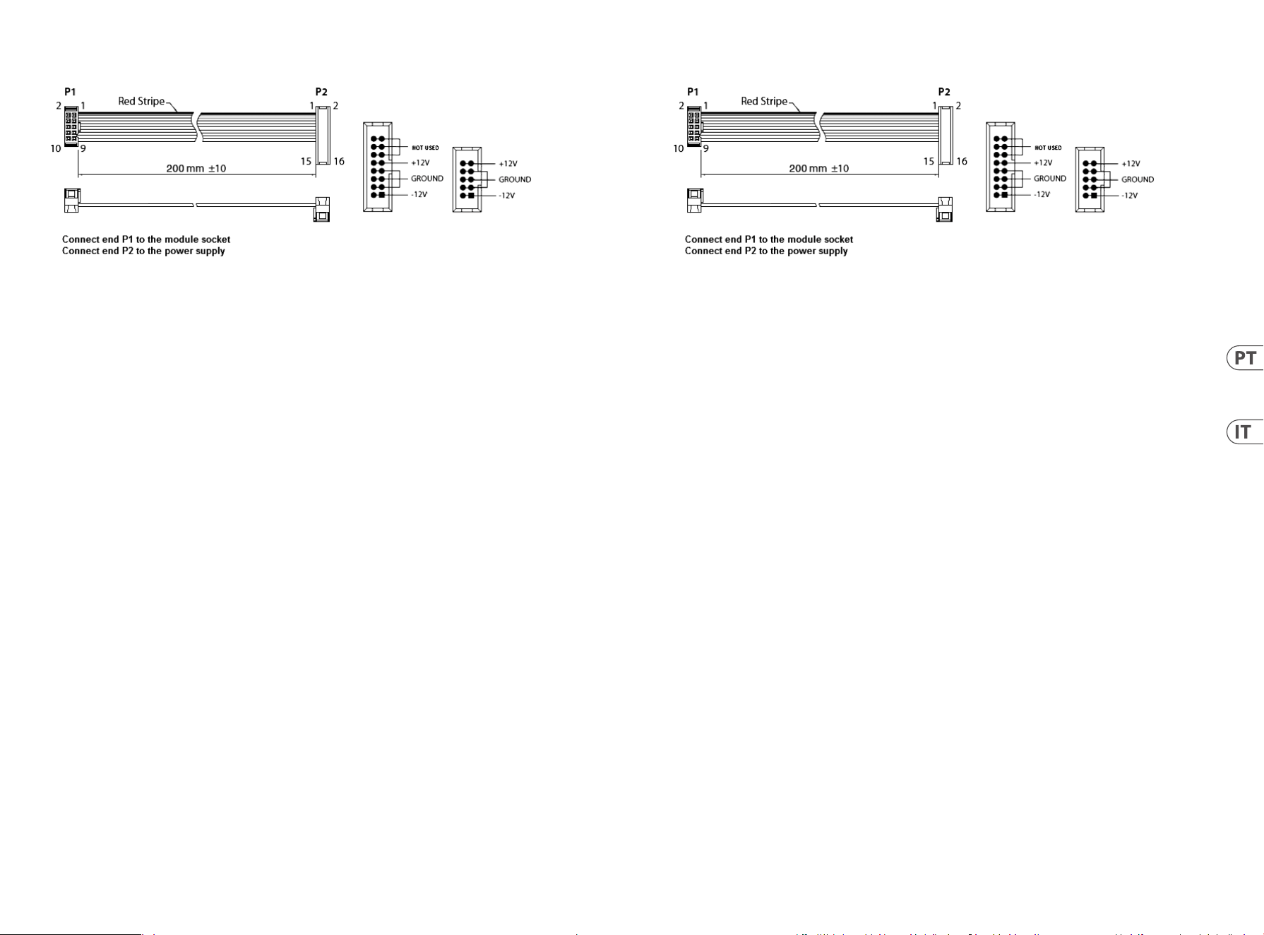
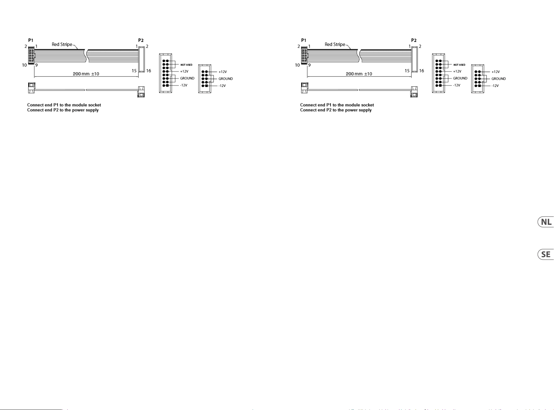
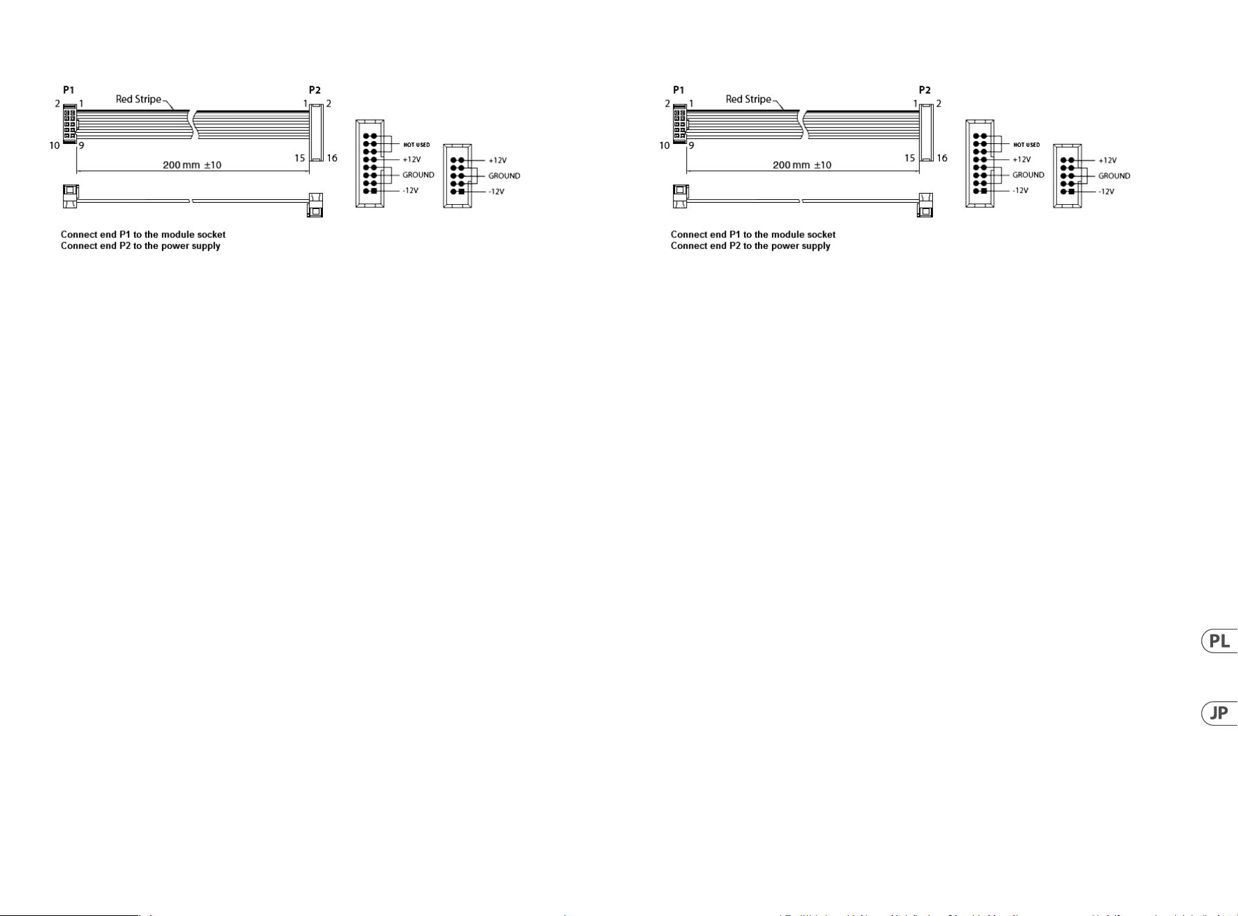
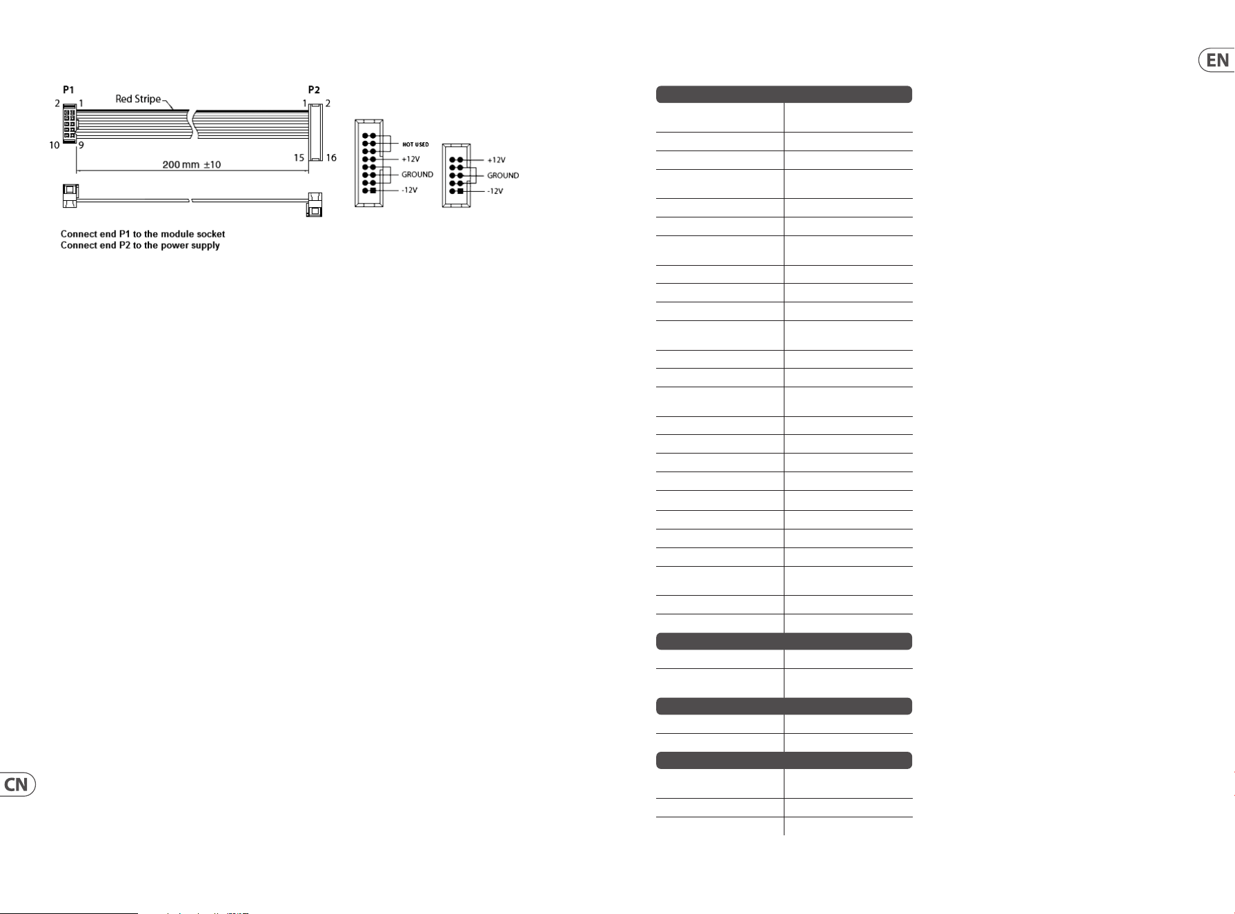
Power Connection
The 961 INTERFACE module comes with the required power cable for connecting to a standard Eurorack power supply
system. Follow these steps to connect power to the module. It is easier to make these connections before the module has
been mounted into a rack case.
1. Turn the power supply or rack case power off and disconnect the power cable.
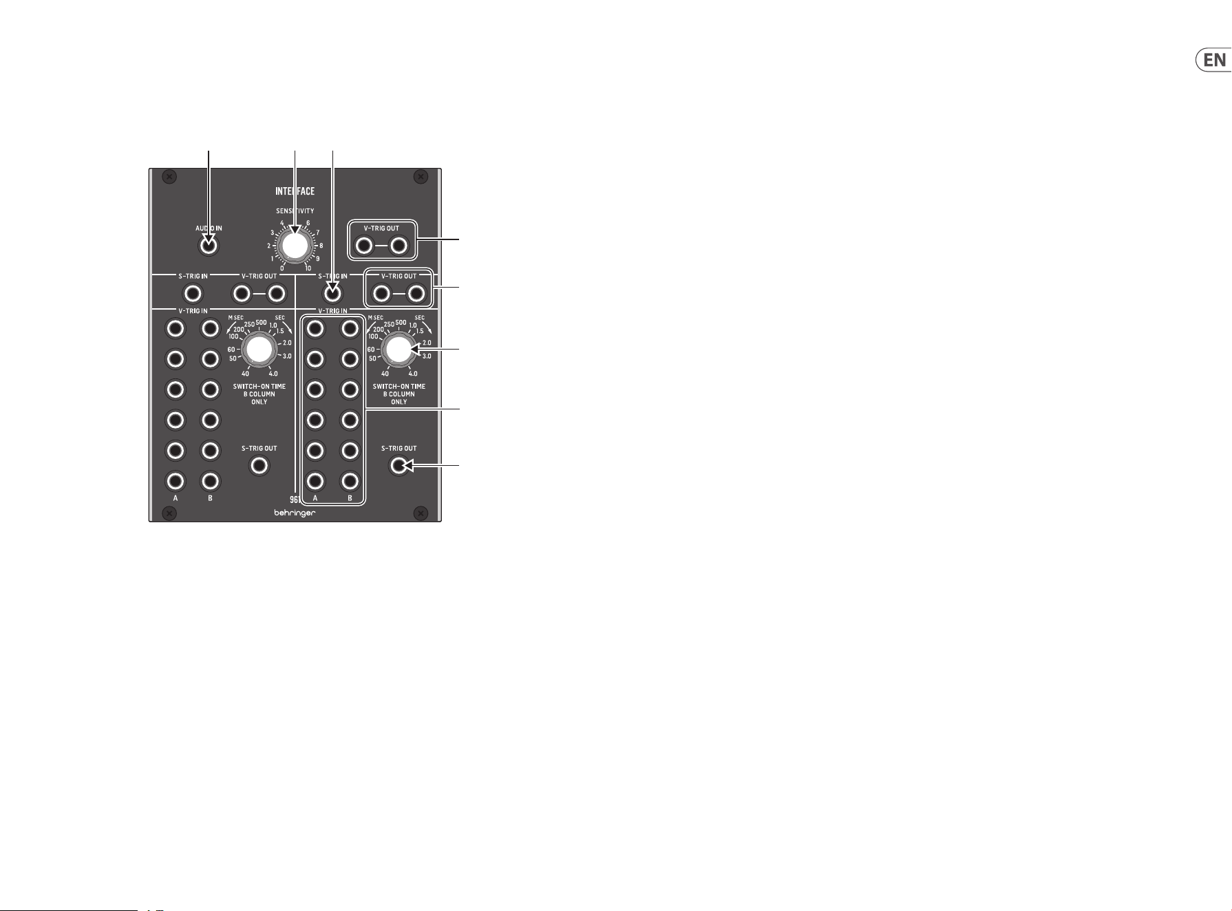
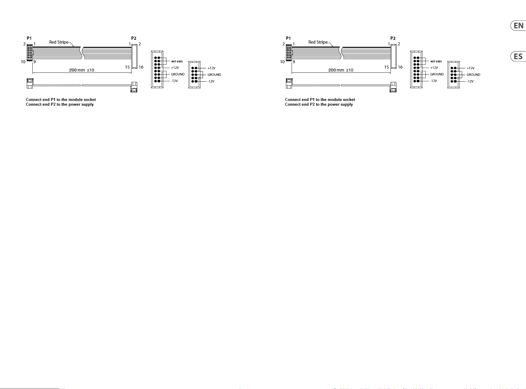
2. Insert the 16-pin connector on the power cable into the socket on the power supply or rack case. The connector has a
tab that will align with the gap in the socket, so it cannot be inserted incorrectly. If the power supply does not have a
keyed socket, be sure to orient pin 1 (-12 V) with the red stripe on the cable.
3. Insert the 10-pin connector into the socket on the back of the module. The connector has a tab that will align with
the socket for correct orientation.
4. After both ends of the power cable have been securely attached, you may mount the module in a case and turn on
the power supply.
Installation
The necessary screws are included with the module for mounting in a Eurorack case. Connect the power cable
before mounting.
Depending on the rack case, there may be a series of fixed holes spaced 2 HP apart along the length of the case, or a track
that allows individual threaded plates to slide along the length of the case. The free-moving threaded plates allow precise
positioning of the module, but each plate should be positioned in the approximate relation to the mounting holes in your
module before attaching the screws.
Hold the module against the Eurorack rails so that each of the mounting holes are aligned with a threaded rail or threaded
plate. Attach the screws part way to start, which will allow small adjustments to the positioning while you get them
all aligned. After the final position has been established, tighten the screws down.
Conexión Eléctrica
El módulo 961 INTERFACE viene con el cable de alimentación necesario para conectarse a un sistema de alimentación
estándar Eurorack. Siga estos pasos para conectar la alimentación al módulo. Es más fácil realizar estas conexiones antes de
que el módulo se haya montado en una caja de rack.
1. Apague la fuente de alimentación o la caja del bastidor y desconecte el cable de alimentación.
2. Inserte el conector de 16 clavijas del cable de alimentación en la toma de la fuente de alimentación o en la caja del
bastidor. El conector tiene una pestaña que se alineará con el espacio en el zócalo, por lo que no se puede insertar
incorrectamente. Si la fuente de alimentación no tiene un enchufe con llave, asegúrese de orientar el pin 1 (-12 V) con
la raya roja en el cable.
3. Inserte el conector de 10 pines en el zócalo en la parte posterior del módulo. El conector tiene una pestaña que se
alineará con el enchufe para una orientación correcta.
4. Una vez que ambos extremos del cable de alimentación se hayan conectado de forma segura, puede montar el
módulo en una caja y encender la fuente de alimentación.
Instalación
Los tornillos necesarios se incluyen con el módulo para el montaje en una caja Eurorack. Conecte el cable de alimentación
antes del montaje.
Dependiendo de la caja del bastidor, puede haber una serie de orificios fijos separados 2 HP a lo largo de la caja, o una
pista que permita que las placas roscadas individuales se deslicen a lo largo de la caja. Las placas roscadas de movimiento
libre permiten un posicionamiento preciso del módulo, pero cada placa debe colocarse en una relación aproximada con los
orificios de montaje en su módulo antes de colocar los tornillos.
Sostenga el módulo contra los rieles Eurorack de modo que cada uno de los orificios de montaje esté alineado con un riel o
placa roscada. Coloque los tornillos parcialmente para comenzar, lo que permitirá pequeños ajustes en la posición mientras
los alinea todos. Una vez establecida la posición final, apriete los tornillos.
22 23Quick Start Guide961 INTERFACE
Netzanschluss
Das 961 INTERFACE-Modul wird mit dem erforderlichen Netzkabel für den Anschluss an ein Standard-Eurorack-
Stromversorgungssystem geliefert. Befolgen Sie diese Schritte, um das Modul mit Strom zu versorgen. Es ist einfacher,
diese Verbindungen herzustellen, bevor das Modul in ein Rackgehäuse eingebaut wurde.
1. Schalten Sie das Netzteil oder das Rackgehäuse aus und ziehen Sie das Netzkabel ab.
2. Stecken Sie den 16-poligen Stecker am Netzkabel in die Buchse am Netzteil oder im Rack-Gehäuse. Der Anschluss
verfügt über eine Lasche, die an der Lücke in der Buchse ausgerichtet ist, sodass sie nicht falsch eingesetzt werden
kann. Wenn das Netzteil keine Schlüsselbuchse hat, achten Sie darauf, Pin 1 (-12 V) mit dem roten Streifen am
Kabel auszurichten.
3. Stecken Sie den 10-poligen Stecker in die Buchse auf der Rückseite des Moduls. Der Anschluss verfügt über eine
Lasche, die zur korrekten Ausrichtung an der Buchse ausgerichtet wird.
4. Nachdem beide Enden des Netzkabels fest angeschlossen wurden, können Sie das Modul in einem Gehäuse
montieren und die Stromversorgung einschalten.
Installation
Die erforderlichen Schrauben sind im Lieferumfang des Moduls für die Montage in einem Eurorack-Gehäuse enthalten.
Schließen Sie das Netzkabel vor der Montage an.
Abhängig vom Rack-Gehäuse kann es eine Reihe von festen Löchern geben, die entlang der Länge des Gehäuses 2 PS
voneinander entfernt sind, oder eine Schiene, mit der einzelne Gewindeplatten entlang der Länge des Gehäuses gleiten
können. Die frei beweglichen Gewindeplatten ermöglichen eine präzise Positionierung des Moduls. Jede Platte sollte
jedoch in der ungefähren Beziehung zu den Befestigungslöchern in Ihrem Modul positioniert werden, bevor Sie die
Schrauben anbringen.
Halten Sie das Modul so gegen die Eurorack-Schienen, dass jedes der Befestigungslöcher mit einer Gewindeschiene oder
einer Gewindeplatte ausgerichtet ist. Bringen Sie die Schrauben teilweise an, um zu beginnen. Dadurch können Sie die
Position geringfügig anpassen, während Sie alle ausrichten. Ziehen Sie die Schrauben fest, nachdem die endgültige
Position festgelegt wurde.
Connexion Électrique
Le module 961 INTERFACE est livré avec le câble d’alimentation requis pour la connexion à un système d’alimentation
standard Eurorack. Suivez ces étapes pour connecter l’alimentation au module. Il est plus facile d’effectuer ces connexions
avant que le module n’ait été monté dans un boîtier de rack.
1. Mettez le bloc d’alimentation ou le boîtier de rack hors tension et débranchez le câble d’alimentation.
2. Insérez le connecteur à 16 broches du câble d’alimentation dans la prise du bloc d’alimentation ou du boîtier du rack.
Le connecteur a une languette qui s’alignera avec l’espace dans la prise, il ne peut donc pas être inséré de manière
incorrecte. Si le bloc d’alimentation n’a pas de prise à clé, veillez à orienter la broche 1 (-12 V) avec la bande rouge sur
le câble.
3. Insérez le connecteur à 10 broches dans la prise à l’arrière du module. Le connecteur a une languette qui s’alignera
avec la prise pour une orientation correcte.
4. Une fois que les deux extrémités du câble d’alimentation ont été solidement fixées, vous pouvez monter le module
dans un boîtier et allumer l’alimentation.
Installation
Les vis nécessaires sont incluses avec le module pour le montage dans un boîtier Eurorack. Connectez le câble
d’alimentation avant le montage.
Selon le cas de rack, il peut y avoir une série de trous fixes espacés de 2 HP sur la longueur du cas, ou une piste qui permet
aux plaques filetées individuelles de glisser le long de la longueur du cas. Les plaques filetées à déplacement libre
permettent un positionnement précis du module, mais chaque plaque doit être positionnée approximativement par
rapport aux trous de montage de votre module avant de fixer les vis.
Maintenez le module contre les rails Eurorack de sorte que chacun des trous de montage soit aligné avec un rail fileté ou
une plaque filetée. Fixez les vis partiellement pour commencer, ce qui permettra de petits ajustements au positionnement
pendant que vous les alignerez tous. Une fois la position finale établie, serrez les vis vers le bas.
24 25Quick Start Guide961 INTERFACE
Conexão de Força
O módulo 961 INTERFACE vem com o cabo de alimentação necessário para conexão a um sistema de fonte de alimentação
Eurorack padrão. Siga estas etapas para conectar a alimentação ao módulo. É mais fácil fazer essas conexões antes que o
módulo seja montado em um gabinete de rack.
1. Desligue a fonte de alimentação ou o gabinete do rack e desconecte o cabo de alimentação.
2. Insira o conector de 16 pinos do cabo de alimentação no soquete da fonte de alimentação ou no gabinete do
rack. O conector possui uma aba que se alinhará com a lacuna no soquete, de forma que não pode ser inserido
incorretamente. Se a fonte de alimentação não tiver um soquete chaveado, certifique-se de orientar o pino 1 (-12 V)
com a faixa vermelha no cabo.
3. Insira o conector de 10 pinos no soquete na parte traseira do módulo. O conector possui uma guia que se alinha ao
soquete para orientação correta.
4. Depois que ambas as extremidades do cabo de alimentação forem firmemente conectadas, você pode montar o
módulo em um gabinete e ligar a fonte de alimentação.
Instalação
Os parafusos necessários estão incluídos com o módulo para montagem em uma caixa Eurorack. Conecte o cabo de
alimentação antes da montagem.
Dependendo da caixa do rack, pode haver uma série de orifícios fixos espaçados de 2 HP ao longo do comprimento da caixa,
ou um trilho que permite que placas roscadas individuais deslizem ao longo do comprimento da caixa. As placas roscadas
de movimento livre permitem o posicionamento preciso do módulo, mas cada placa deve ser posicionada em uma relação
aproximada com os orifícios de montagem em seu módulo antes de prender os parafusos.
Segure o módulo contra os trilhos Eurorack de forma que cada um dos orifícios de montagem fiquem alinhados com
um trilho ou placa rosqueada. Prenda os parafusos parcialmente para começar, o que permitirá pequenos ajustes no
posicionamento enquanto você os alinha. Depois de estabelecida a posição final, aperte os parafusos.
Connessione di Alimentazione
Il modulo 961 INTERFACE viene fornito con il cavo di alimentazione necessario per il collegamento a un sistema di
alimentazione Eurorack standard. Seguire questi passaggi per collegare l’alimentazione al modulo. È più facile effettuare
questi collegamenti prima che il modulo sia stato montato in un case rack.
1. Spegnere l’alimentatore o il case del rack e scollegare il cavo di alimentazione.
2. Inserire il connettore a 16 pin del cavo di alimentazione nella presa sull’alimentatore o sulla custodia del rack.
Il connettore ha una linguetta che si allineerà con lo spazio nella presa, quindi non può essere inserito in modo errato.
Se l’alimentatore non dispone di una presa con chiave, assicurarsi di orientare il pin 1 (-12 V) con la striscia rossa
sul cavo.
3. Inserire il connettore a 10 pin nella presa sul retro del modulo. Il connettore ha una linguetta che si allineerà con la
presa per un corretto orientamento.
4. Dopo che entrambe le estremità del cavo di alimentazione sono state fissate saldamente, è possibile montare il
modulo in una custodia e accendere l’alimentatore.
Installazione
Le viti necessarie sono incluse con il modulo per il montaggio in una custodia Eurorack. Collegare il cavo di alimentazione
prima del montaggio.
A seconda del case del rack, potrebbero esserci una serie di fori fissi distanziati di 2 HP l’uno dall’altro lungo la lunghezza
del case, o un binario che consente alle singole piastre filettate di scorrere lungo la lunghezza del case. Le piastre filettate
a movimento libero consentono un posizionamento preciso del modulo, ma ciascuna piastra deve essere posizionata in
relazione approssimativa con i fori di montaggio nel modulo prima di fissare le viti.
Tenere il modulo contro le guide Eurorack in modo che ciascuno dei fori di montaggio sia allineato con una guida filettata
o una piastra filettata. Attaccare parzialmente le viti per iniziare, il che consentirà piccoli aggiustamenti al posizionamento
mentre le si allineano tutte. Dopo aver stabilito la posizione finale, serrare le viti.
26 27Quick Start Guide961 INTERFACE
Strömanslutning
961 INTERFACE-modulen levereras med den nödvändiga strömkabeln för anslutning till ett vanligt Eurorack-nätaggregat.
Följ dessa steg för att ansluta ström till modulen. Det är lättare att göra dessa anslutningar innan modulen har monterats i
ett rackfodral.
1. Stäng av strömmen eller rackhöljet och koppla bort strömkabeln.
2. Sätt i den 16-poliga kontakten på strömkabeln i uttaget på strömförsörjningen eller rackfodralet. Kontaktdonet har
en flik som kommer i linje med springan i uttaget så att den inte kan sättas in felaktigt. Om strömförsörjningen inte
har ett nyckeluttag, se till att orientera stift 1 (-12 V) med den röda remsan på kabeln.
3. Sätt i 10-polig kontakt i uttaget på baksidan av modulen. Kontaktdonet har en flik som kommer i linje med uttaget
för korrekt orientering.
4. När båda ändarna av strömkabeln har anslutits ordentligt kan du montera modulen i ett fodral och slå på
strömförsörjningen.
Installation
De nödvändiga skruvarna ingår i modulen för montering i ett Eurorack-fodral. Anslut strömkabeln före montering.
Beroende på rackfodralet kan det finnas en serie fasta hål som är åtskilda 2 hk längs höljets längd eller ett spår som gör att
enskilda gängade plattor kan glida längs höljets längd. De fritt rörliga gängade plattorna möjliggör exakt positionering av
modulen, men varje platta bör placeras i ungefärlig relation till monteringshålen i din modul innan skruvarna fästs.
Håll modulen mot Eurorack-skenorna så att var och en av monteringshålen är inriktade mot en gängad skena eller gängad
platta. Fäst skruvarna delvis för att börja, vilket möjliggör små justeringar av positioneringen medan du justerar dem alla.
När den slutliga positionen har fastställts drar du åt skruvarna.
Stroomaansluiting
De 961 INTERFACE-module wordt geleverd met de benodigde voedingskabel voor aansluiting op een standaard Eurorack-
voedingssysteem. Volg deze stappen om de module van stroom te voorzien. Het is gemakkelijker om deze aansluitingen te
maken voordat de module in een rekbehuizing is gemonteerd.
1. Schakel de voeding of de rekbehuizing uit en koppel de voedingskabel los.
2. Steek de 16-pins connector van de voedingskabel in de aansluiting op de voedingseenheid of rekbehuizing.
De connector heeft een lipje dat wordt uitgelijnd met de opening in de socket, zodat deze niet verkeerd kan worden
geplaatst. Als de voeding geen contactdoos met sleutel heeft, zorg er dan voor dat pen 1 (-12 V) met de rode streep
op de kabel wordt georiënteerd.
3. Steek de 10-pins connector in de aansluiting aan de achterkant van de module. De connector heeft een lipje dat
uitgelijnd is met de aansluiting voor de juiste oriëntatie.
4. Nadat beide uiteinden van de voedingskabel stevig zijn bevestigd, kunt u de module in een hoesje monteren en de
voeding inschakelen.
Installatie
De benodigde schroeven worden bij de module geleverd voor montage in een Eurorack-koffer. Sluit de voedingskabel aan
voor montage.
Afhankelijk van de rackbehuizing kan er een reeks vaste gaten zijn die 2 HP uit elkaar liggen over de lengte van de
behuizing, of een rail waarmee afzonderlijke platen met schroefdraad langs de lengte van de behuizing kunnen schuiven.
De vrij bewegende plaatjes met schroefdraad maken een nauwkeurige positionering van de module mogelijk, maar
elke plaat moet ongeveer in verhouding tot de montagegaten in uw module worden geplaatst voordat u de schroeven
bevestigt.
Houd de module tegen de Eurorack-rails zodat elk van de montagegaten is uitgelijnd met een rail met schroefdraad of
een plaat met schroefdraad. Bevestig de schroeven halverwege om te beginnen, waardoor kleine aanpassingen aan
de positionering mogelijk zijn terwijl u ze allemaal op één lijn krijgt. Nadat de definitieve positie is bepaald, draait u de
schroeven vast.
28 29Quick Start Guide961 INTERFACE
Podłączenie Zasilania
Moduł 961 INTERFACE jest dostarczany z wymaganym kablem zasilającym do podłączenia do standardowego systemu
zasilania Eurorack. Wykonaj poniższe czynności, aby podłączyć zasilanie do modułu. Łatwiej jest wykonać te połączenia
przed zamontowaniem modułu w obudowie rack.
1. Wyłącz zasilacz lub obudowę szafy i odłącz kabel zasilający.
2. Włóż 16-stykowe złącze przewodu zasilającego do gniazda w zasilaczu lub w szafie typu Rack. Złącze ma wypustkę,
która będzie wyrównana ze szczeliną w gnieździe, więc nie można jej nieprawidłowo włożyć. Jeśli zasilacz nie ma
gniazda z kluczem, należy zorientować styk 1 (-12 V) z czerwonym paskiem na kablu.
3. Włóż 10-pinowe złącze do gniazda z tyłu modułu. Złącze ma wypustkę, która będzie wyrównana z gniazdem, aby
zapewnić prawidłową orientację.
4. Po solidnym zamocowaniu obu końców kabla zasilającego można zamontować moduł w obudowie i włączyć zasilacz.
Instalacja
Do modułu dołączone są niezbędne śruby do montażu w skrzynce Eurorack. Podłącz kabel zasilający przed montażem.
W zależności od obudowy szafy może występować szereg stałych otworów rozmieszczonych w odstępach 2 HP na całej
długości obudowy lub prowadnica, która umożliwia przesuwanie pojedynczych gwintowanych płyt wzdłuż całej obudowy.
Swobodnie poruszające się gwintowane płytki umożliwiają precyzyjne ustawienie modułu, ale każda płyta powinna być
ustawiona w przybliżeniu w stosunku do otworów montażowych w module przed przykręceniem śrub.
Przytrzymaj moduł na szynach Eurorack, tak aby każdy z otworów montażowych był wyrównany z szyną gwintowaną lub
płytą gwintowaną. Wkręć śruby częściowo, aby rozpocząć, co pozwoli na drobne korekty położenia, gdy wszystkie zostaną
wyrównane. Po ustaleniu ostatecznego położenia dokręcić śruby.
電源接続
961 INTERFACE モ ジ ュ ー ル に は 、標 準 の Eurorack 電源システムに接続するために必要な電源ケーブルが付
属しています。 次の手順に従って、モジュールに電源を接続します。モジュールをラックケースに取り付
ける前に、これらの接続を行う方が簡単です。
1. 電源装置またはラックケースの電源を切り、電源ケーブルを外します。
2. 電 源 ケーブルの 16 ピンコネクタを電源装置またはラックケースのソケットに挿入します。コネク
タにはソケットの隙間に合うタブが付いているので、間違って挿入することはできません。電源
装置にキー付きソケットがない場合は、必ずピン 1 (-12 V) をケーブルの赤いストライプに向けて
ください。
3. モジュールの背面にあるソケットに 10 ピンコネクタを挿入します。コネクタには、正しい方向に
向 けてソケットと位 置 合 わ せ するタブ が ありま す。
4. 電源ケーブルの両端をしっかりと取り付けたら、モジュールをケースに取り付けて電源を入れ
ます。
インストール
必要なネジは、ユーロラックケースに取り付けるためのモジュールに含まれています。取り付ける前に
電 源 ケーブル を接 続 してください 。
ラックケースによっては 、ケースの 長さに 沿 って 2 HP 間隔で配置された一連の固定穴、または個々のネ
ジ付きプレートをケースの長さに沿ってスライドできるトラックが 存在する場合があります。自由に動
くネジ付きプレートにより、モジュールを正確に配置できますが、ネジを取り付ける前に、各プレート
をモジュールの取り付け穴とほぼ同じ位置に配置する必要があります。
モジュールをユーロラックレールに押し付けて、各取り付け穴がネジ付きレールまたはネジ付きプレー
トと揃うようにします。開始の途中でネジを取り付けます。これにより、すべてのネジを揃えながら、
位置を微調整できます。 最終位置が決まったら、ネジを締めます。
30 31Quick Start Guide961 INTERFACE
电源连接
961 INTERFACE 模块随附所需的电源线, 用于连接到标准 Eurorack 电源系统。 请按照以下步骤将电源连接
到模块。 在将模块安装到机架盒中之前, 进行这些连接会更容易。
1. 关闭电源或机架式机箱的电源, 然后断开电源线的连接。
2. 将电源线上的 16 针连接器插入电源或机架盒上的插座。 该连接器具有一个卡舌, 该卡舌将与插槽中
的间隙对齐, 因此不会被错误地插入。 如果电源没有键控插座, 请确保将插针 1 (-12 V) 的方向与电缆
上的红色条纹对准。
3. 将 10 针接器插入模块背面的插槽中。 连接器具有一个卡舌, 该卡舌将与插座对齐以正确定向。
4. 在牢固连接电源线的两端之后, 您可以将模块安装在盒中并打开电源。
安装
模块随附了必要的螺钉, 用于将其安装在 Eurorack 箱中。 安装前, 请先连接电源线。
根据机架机箱的不同, 可能会有一系列沿机箱长度方向相距 2 HP 的固定孔, 或者是一条允许单个螺
纹板沿机箱长度方向滑动的导轨。 可以自由移动的螺纹板可以精确定位模块, 但是在安装螺钉之前,
应将每个板的位置与模块上的安装孔大致成一定关系。
将模块靠在 Eurorack 导轨上, 以使每个安装孔都与螺纹导轨或螺纹板对齐。 从头开始固定螺丝, 在对
齐时可以对位置进行细微调整。 确定最终位置后, 拧紧螺钉。
Specifications
Signal Connections
Audio-to-voltage-trigger
converter
1 x circuit
Audio in 1 x 3.5 mm jack, AC coupled
Input impedance > 3 kΩ unbalanced
V-trig out 2 x 3.5 mm parallel jacks,
DC coupled
Output Impedance < 2 kΩ, unbalanced
Maximum output level +5 V
Switch-to-voltage-trigger
converter
2 x circuit (left and right)
S-trig in 1 x 3.5 mm jack, DC coupled
Operation Pull low to trigger
Maximum input level +12 V
V-trig out 2 x 3.5 mm parallel jacks,
DC coupled
Output Impedance < 2 kΩ, unbalanced
Maximum output level +5 V
Voltage-to-switch-trigger
converter
2 x circuit (left and right)
V-trig in A 6 x 3.5 mm jacks, DC coupled
Input Impedance 10 kΩ, unbalanced
Maximum input level +5 V
Minimum level to trigger + 1.5 V
V-trig in B 6 x 3.5 mm jacks, AC coupled
Input Impedance 10 kΩ unbalanced
Maximum input level +5 V
Minimum level to trigger + 1.5 V
S-trig out 1 x 3.5 mm jack,
DC coupled
Operation Active low
Output level 0 V to +12 V pullup resistor
Controls
Sensitivity 1 x rotary knob
Switch-on time 2 x rotary knob
40 ms to 4 s, adjustable
Power
Power supply Eurorack
Current draw 50 mA (+12 V)
Physical
Dimensions 35 x 106 x 129 mm
(1.4 x 4.2 x 5.1")
Rack units 21 HP
Weight 0.22 kg (0.49 lbs)
32 33Quick Start Guide961 INTERFACE
FEDERAL COMMUNICATIONS
COMMISSION COMPLIANCE
INFORMATION
Behringer
961 INTERFACE
Responsible Party Name: Music Tribe Commercial NV Inc.
Address: 122 E. 42nd St.1,
8th Floor NY, NY 10168,
United States
Email Address: [email protected]
961 INTERFACE
This equipment has been tested and found to comply with
the limits for a Class B digital device, pursuant to part
15 of the FCC Rules. These limits are designed to provide
reasonable protection against harmful interference in
a residential installation. This equipment generates,
uses and can radiate radio frequency energy and, if not installed
and used in accordance with the instructions, may cause harmful
interference to radio communications. However, there is no
guarantee that interference will not occur in a particular installation.
If this equipment does cause harmful interference to radio or
television reception, which can be determined by turning the
equipment off and on, the user is encouraged to try to correct the
interference by one or more of the following measures:
• • Reorient or relocate the receiving antenna.
• • Increase the separation between the equipment and receiver.
• • Connect the equipment into an outlet on a circuit different
from that to which the receiver is connected.
• • Consult the dealer or an experienced radio/TV
technician for help.
This equipment complies with Part 15 of the FCC rules. Operation
is subject to the following two conditions:
(1) this device may not cause harmful interference, and
(2) this device must accept any interference received, including
interference that may cause undesired operation.
Important information:
Changes or modifications to the equipment not expressly
approved by Music Tribe can void the user’s authority to
use the equipment.
Hereby, Music Tribe declares that this product is in compliance
with Directive 2014/30/EU, Directive 2011/65/EU and Amendment
2015/863/EU, Directive 2012/19/EU, Regulation 519/2012 REACH
SVHC and Directive 1907/2006/EC.
Full text of EU DoC is available at https://community.musictribe.com/
EU Representative: Music Tribe Brands DK A/S
Address: Gammel Strand 44, DK-1202 København K, Denmark
UK Representative: Music Tribe Brands UK Ltd.
Address: 8
th
Floor, 20 Farringdon Street London EC4A 4AB,
United Kingdom
Correct disposal of this product: This symbol
indicates that this product must not be disposed
of with household waste, according to the WEEE
Directive (2012/19/EU) and your national law.
This product should be taken to a collection
center licensed for the recycling of waste
electrical and electronic equipment (EEE). The
mishandling of this type of waste could have a possible negative
impact on the environment and human health due to potentially
hazardous substances that are generally associated with EEE. At the
same time, your cooperation in the correct disposal of this product
will contribute to the efficient use of natural resources. For more
information about where you can take your waste equipment for
recycling, please contact your local city office, or your household
waste collection service.
型号: 961 INTERFACE 合成器与采样器
制造商: Music Tribe Commercial FZE –
Made in China 中国制造
CAN ICES–003 (B)/NMB–003 (B)
技术参数
信号连接
音频电压触发转换器
1 个电路
音频输入
1 x 3.5 mm 插孔,
交流耦合
输入阻抗
> 3 kΩ 不平衡
V 触发
2 个 3.5 mm 并行插孔,
直流耦合
输出阻抗
< 2 kΩ, 不平衡
最大输出水平
+5 V
开关电压触发转换器
2 x 电路 (左右)
S 触发
1 个 3.5 mm 插孔,
直流耦合
手术 拉低触发
最大输入电平
+12 V
V 触发
2 个 3.5 mm 并行插孔,
直流耦合
输出阻抗
<2 kΩ, 不平衡
最大输出水平
+5 V
电压开关触发转换器
2 x 电路 (左右)
A 中的 V-trig
6 个 3.5 mm 插孔,
直流耦合
输入阻抗
10 kΩ, 不平衡
最大输入电平
+5 V
最低触发水平
+ 1.5 V
B 中的 V-trig
6 x 3.5 mm 插孔,
交流耦合
输入阻抗
10 kΩ 不平衡
最大输入电平
+5 V
最低触发水平
+ 1.5 V
S 触发
1 个 3.5 mm 插孔,
直流耦合
手术 活跃低
输出水平
0 V 至 +12 V 上拉电阻
控制项
灵敏度
1 个旋钮
开机时间
2 x 旋钮 40 ms 至 4 s,
可调
力量
电源供应 欧陆架
电流消耗
50 mA (+12 V)
身体的
方面
35 x 106 x 129 mm
(1.4 x 4.2 x 5.1")
机架单位
21 HP
重量
0.22 kg (0.49 lbs)

We Hear You
