Quick Start Guide
OSCILLATOR MODULE 1004
Legendary 2500 Series Dual Core VCO Module for Eurorack
V 1.0
2 3Quick Start GuideOSCILLATOR MODULE 1004
(EN) Safety Instruction
1. Please read and follow all
instructions.
2. Keep the apparatus away from
water, except for outdoor products..
3. Clean only with a dry cloth.
4. Do not block any ventilation
openings. Install in accordance with the
manufacturer’s instructions.
5. Do not install near any heat
sources such as radiators, heat
registers, stoves or other apparatus
(including amplifiers) that
produce heat.
6. Use only attachments/accessories
specified by the manufacturer.
7. Use only
specified carts,
stands, tripods,
brackets, or tables.
Use caution to
prevent tip-over
when moving the cart/apparatus
combination.
8. Avoid installing in confined spaces
like bookcases.
9. Do not place near naked flame
sources, such as lighted candles.
10. Operating temperature range 5°
to 45°C (41° to 113°F).
LEGAL DISCLAIMER
Music Tribe accepts no liability for
any loss which may be suffered by
any person who relies either wholly
or in part upon any description,
photograph, or statement contained
herein. Technical specifications,
appearances and other information
are subject to change without notice.
All trademarks are the property
of their respective owners. Midas,
Klark Teknik, Lab Gruppen, Lake,
Tannoy, Turbosound, TC Electronic,
TC Helicon, Behringer, Bugera, Aston
Microphones and Coolaudio are
trademarks or registered trademarks
of Music Tribe Global Brands Ltd.
© Music Tribe Global Brands Ltd.
2024 All rights reserved.
LIMITED WARRANTY
For the applicable warranty terms
and conditions and additional
information regarding Music Tribe’s
Limited Warranty, please see
complete details online at community.
musictribe.com/support.
(ES)
Instrucción de seguridad
1. Por favor, lea y siga todas las
instrucciones.
2. Mantenga el aparato alejado
del agua, excepto para productos
destinados al uso en exteriores.
3. Limpie solo con un paño seco.
4. No bloquee ninguna abertura de
ventilación. Instale de acuerdo con las
instrucciones del fabricante.
5. No instale cerca de fuentes de
calor como radiadores, registros
de calor, estufas u otros aparatos
(incluyendo amplificadores) que
generen calor.
6. Utilice solo accesorios
especificados por el fabricante.
7. Use solo
carros, soportes,
trípodes, soportes
o mesas
especificados.
Tenga precaución
para evitar el vuelco al mover la
combinación carro/aparato.
8. Evite la instalación en espacios
confinados como estanterías.
9. No colocar cerca de fuentes de
llama desnuda, como velas encendidas.
10. Rango de temperatura de
funcionamiento de 5° a 45° C
(41° a 113° F).
NEGACIÓN LEGAL
Music Tribe no admite ningún tipo
de responsabilidad por cualquier
daño o pérdida que pudiera sufrir
cualquier persona por confiar total
o parcialmente en la descripciones,
fotografías o afirmaciones
contenidas en este documento.
Las especificaciones técnicas,
imágenes y otras informaciones
contenidas en este documento están
sujetas a modificaciones sin previo
aviso. Todas las marcas comerciales
que aparecen aquí son propiedad
de sus respectivos dueños. Midas,
Klark Teknik, Lab Gruppen, Lake,
Tannoy, Turbosound, TC Electronic,
TC Helicon, Behringer, Bugera, Aston
Microphones y Coolaudio son marcas
comerciales o marcas registradas
de Music Tribe Global Brands Ltd.
© Music Tribe Global Brands Ltd.
2024 Reservados todos los derechos.
GARANTÍA LIMITADA
Si quiere conocer los detalles y
condiciones aplicables de la garantía
así como información adicional sobre
la Garantía limitada de Music Tribe,
consulte online toda la información
en la web community.musictribe.
com/support.
(FR) Consignes de sécurité
1. Veuillez lire et suivre toutes les
instructions.
2. Gardez l'appareil éloigné de l'eau,
sauf pour les produits destinés à une
utilisation en extérieur.
3. Nettoyez uniquement avec un
chiffon sec.
4. Ne bloquez aucune ouverture de
ventilation. Installez conformément
aux instructions du fabricant.
5. N'installez pas près de sources de
chaleur telles que radiateurs, grilles de
chaleur, cuisinières ou autres appareils
(y compris les amplificateurs) qui
produisent de la chaleur.
6. Utilisez uniquement les
accessoires spécifiés par le fabricant.
7. Utilisez
uniquement des
chariots, des
supports, des
trépieds, des
supports ou des
tables spécifiés. Faites attention pour
éviter le renversement lors du
déplacement de la combinaison
chariot/appareil.
8. Évitez l'installation dans
des espaces confinés comme les
bibliothèques.
9. Ne pas placer près de sources
de flamme nue, telles que des
bougies allumées.
10. Plage de température de
fonctionnement de 5° à 45° C
(41° à 113)
DÉNI LÉGAL
Music Tribe ne peut être tenu pour
responsable pour toute perte pouvant
être subie par toute personne se
fiant en partie ou en totalité à
toute description, photographie
ou affirmation contenue dans ce
document. Les caractéristiques,
l’apparence et d’autres informations
peuvent faire l’objet de modifications
sans notification. Toutes les marques
appartiennent à leurs propriétaires
respectifs. Midas, Klark Teknik,
Lab Gruppen, Lake, Tannoy,
Turbosound, TC Electronic, TC Helicon,
Behringer, Bugera, Aston Microphones
et Coolaudio sont des marques ou
marques déposées de Music Tribe
Global Brands Ltd. © Music Tribe Global
Brands Ltd. 2024 Tous droits réservés.
GARANTIE LIMITÉE
Pour connaître les termes et conditions
de garantie applicables, ainsi que
les informations supplémentaires et
détaillées sur la Garantie Limitée de
Music Tribe, consultez le site Internet
community.musictribe.com/support.
(DE) Wichtige
Sicherheitshinweise
1. Bitte lesen Sie alle Anweisungen
sorgfältig durch und befolgen
Sie diese.
2. Halten Sie das Gerät von Wasser
fern, außer für Produkte, die für den
Außeneinsatz vorgesehen sind.
3. Reinigen Sie es nur mit einem
trockenen Tuch.
4. Blockieren Sie keine
Belüftungsöffnungen. Installieren
Sie gemäß den Anweisungen
des Herstellers.
5. Installieren Sie nicht in der Nähe
von Wärmequellen wie Heizkörpern,
Heizregistern, Öfen oder anderen
Geräten (einschließlich Verstärkern),
die Wärme erzeugen.
6. Verwenden Sie nur Zubehörteile,
die vom Hersteller angegeben sind.
7. Verwenden
Sie nur
spezifizierte
Wagen, Ständer,
Stative,
Halterungen oder
Tische. Achten Sie darauf, beim
Bewegen der Wagen-Geräte-
Kombination ein Umkippen
zu vermeiden.
8. Vermeiden Sie die Installation in
beengten Räumen wie Bücherregalen.
9. Nicht in der Nähe von offenen
Flammenquellen platzieren,
wie brennende Kerzen.
10. Betriebstemperaturbereich von 5°
bis 45°C (41° bis 113°F).
HAFTUNGSAUSSCHLUSS
Music Tribe übernimmt keine Haftung
für Verluste, die Personen entstanden
sind, die sich ganz oder teilweise auf
hier enthaltene Beschreibungen,
Fotos oder Aussagen verlassen haben.
Technische Daten, Erscheinungsbild
und andere Informationen können
ohne vorherige Ankündigung
geändert werden. Alle Warenzeichen
sind Eigentum der jeweiligen
Inhaber. Midas, Klark Teknik, Lab
Gruppen, Lake, Tannoy, Turbosound,
TC Electronic, TC Helicon, Behringer,
Bugera, Aston Microphones und
Coolaudio sind Warenzeichen oder
eingetragene Warenzeichen der
Music Tribe Global Brands Ltd.
© Music Tribe Global Brands Ltd.
2024 Alle Rechte vorbehalten.
BESCHRÄNKTE GARANTIE
Die geltenden Garantiebedingungen
und zusätzliche Informationen
bezüglich der von Music Tribe
gewährten beschränkten Garantie
finden Sie online unter community.
musictribe.com/support.
(PT) Instruções de
Seguranç Importantes
1. Por favor, leia e siga todas as
instruções.
2. Mantenha o aparelho longe da
água, exceto para produtos destinados
ao uso externo.
3. Limpe apenas com um pano seco.
4. Não bloqueie nenhuma abertura
de ventilação. Instale de acordo com as
instruções do fabricante.
5. Não instale próximo a fontes
de calor, como radiadores, grelhas
de calor, fogões ou outros aparelhos
(incluindo amplificadores) que
gerem calor.
6. Use apenas acessórios
especificados pelo fabricante.
7. Use apenas
carrinhos,
suportes, tripés,
suportes ou mesas
especificados.
Tenha cuidado
para evitar tombamentos ao mover a
combinação carrinho/aparelho.
8. Evite instalar em espaços
confinados, como estantes.
9. Não coloque perto de fontes de
chama nua, como velas acesas.
10. Intervalo de temperatura de
operação de 5° a 45° C (41° a 113° F).
LEGAL RENUNCIANTE
O Music Tribe não se responsabiliza
por perda alguma que possa ser
sofrida por qualquer pessoa que
dependa, seja de maneira completa
ou parcial, de qualquer descrição,
fotografia, ou declaração aqui
contidas. Dados técnicos, aparências
e outras informações estão sujeitas
a modificações sem aviso prévio.
Todas as marcas são propriedade
de seus respectivos donos. Midas,
Klark Teknik, Lab Gruppen, Lake,
Tannoy, Turbosound, TC Electronic,
4 5Quick Start GuideOSCILLATOR MODULE 1004
TC Helicon, Behringer, Bugera,
Aston Microphones e Coolaudio
são marcas ou marcas registradas
do Music Tribe Global Brands Ltd.
© Music Tribe Global Brands Ltd.
2024 Todos direitos reservados.
GARANTIA LIMITADA
Para obter os termos de garantia
aplicáveis e condições e informações
adicionais a respeito da garantia
limitada do Music Tribe, favor verificar
detalhes na íntegra através do website
community.musictribe.com/support.
(IT) Istruzioni di sicurezza
importanti
1. Per favore, leggere e seguire tutte
le istruzioni.
2. Mantenere l'apparecchio lontano
dall'acqua, tranne per i prodotti
destinati all'uso all'aperto.
3. Pulire solo con un panno asciutto.
4. Non ostruire alcuna apertura di
ventilazione. Installare in conformità
alle istruzioni del produttore.
5. Non installare vicino a fonti di
calore come termosifoni, bocchette
di calore, fornelli o altri apparecchi
(compresi gli amplificatori) che
producono calore.
6. Utilizzare solo accessori specificati
dal produttore.
7. Usare solo
carrelli, supporti,
treppiedi, staffe o
tavoli specificati.
Prestare
attenzione per
evitare il ribaltamento durante lo
spostamento della combinazione
carrello/apparecchio.
8. Evitare l'installazione in spazi
confinati come librerie.
9. Non posizionare vicino a fonti di
fiamma nude, come candele accese.
10. Intervallo di temperatura
di funzionamento da 5° a 45° C
(41° a 113° F)
DISCLAIMER LEGALE
Music Tribe non si assume alcuna
responsabilità per eventuali danni che
possono essere subiti da chiunque si
affidi in tutto o in parte a qualsiasi
descrizione, fotografia o dichiarazione
contenuta qui. Specifiche tecniche,
aspetti e altre informazioni sono
soggette a modifiche senza preavviso.
Tutti i marchi sono di proprietà
dei rispettivi titolari. Midas, Klark
Teknik, Lab Gruppen, Lake, Tannoy,
Turbosound, TC Electronic, TC Helicon,
Behringer, Bugera, Aston Microphones
e Coolaudio sono marchi o marchi
registrati di Music Tribe Global Brands
Ltd. © Music Tribe Global Brands Ltd.
2024 Tutti i diritti riservati.
GARANZIA LIMITATA
Per i termini e le condizioni di garanzia
applicabili e le informazioni aggiuntive
relative alla garanzia limitata di Music
Tribe, consultare online i dettagli
completi su community.musictribe.
com/support.
(NL) Belangrijke
veiligheidsvoorschriften
1. Lees alsjeblieft alle instructies en
volg deze op.
2. Houd het apparaat uit de buurt
van water, behalve voor producten die
bedoeld zijn voor buitengebruik.
3. Reinig alleen met een droge doek.
4. Blokker geen ventilatieopeningen.
Installeer volgens de instructies van de
fabrikant.
5. Installeer niet in de buurt van
warmtebronnen zoals radiatoren,
warmte registers, fornuizen of andere
apparaten (inclusief versterkers) die
warmte produceren.
6. Gebruik alleen accessoires die
door de fabrikant zijn gespecificeerd.
7. Gebruik
alleen
gespecificeerde
karren, standaards,
statieven, beugels
of tafels. Wees
voorzichtig om kantelen te voorkomen
bij het verplaatsen van de kar/
apparaatcombinatie.
8. Vermijd installatie in afgesloten
ruimtes zoals boekenkasten.
9. Plaats niet in de buurt
van naakte vlambronnen,
zoals brandende kaarsen.
10. Bedrijfstemperatuurbereik van 5°
tot 45°C (41° tot 113°F).
WETTELIJKE ONTKENNING
Music Tribe aanvaardt geen
aansprakelijkheid voor enig verlies
dat kan worden geleden door een
persoon die geheel of gedeeltelijk
vertrouwt op enige beschrijving,
foto of verklaring hierin. Technische
specificaties, verschijningen en andere
informatie kunnen zonder voorafgaande
kennisgeving worden gewijzigd. Alle
handelsmerken zijn eigendom van hun
respectievelijke eigenaren. Midas, Klark
Teknik, Lab Gruppen, Lake, Tannoy,
Turbosound, TC Electronic, TC Helicon,
Behringer, Bugera, Aston Microphones
en Coolaudio zijn handelsmerken of
gedeponeerde handelsmerken van
Music Tribe Global Brands Ltd. © Music
Tribe Global Brands Ltd. 2024 Alle
rechten voorbehouden.
BEPERKTE GARANTIE
Voor de toepasselijke
garantievoorwaarden en aanvullende
informatie met betrekking tot de
beperkte garantie van Music Tribe,
zie de volledige details online op
community.musictribe.com/support.
(SE) Viktiga
säkerhetsanvisningar
1. Vänligen läs och följ alla
instruktioner noggrant.
2. Håll apparaten borta från vatten,
förutom för utomhusprodukter.
3. Rengör endast med en torr trasa.
4. Blockera inte några
ventilationsöppningar. Installera enligt
tillverkarens anvisningar.
5. Installera inte nära några
värmekällor som element,
värmeregistrar, spisar eller andra
apparater (inklusive förstärkare) som
genererar värme.
6. Använd endast tillbehör som
anges av tillverkaren.
7. Använd
endast
specificerade
vagnar, ställ, stativ,
fästen eller bord.
Var försiktig för att
undvika att vagnen/
apparatkombinationen tippar när
den flyttas.
8. Undvik installation i trånga
utrymmen som bokhyllor.
9. Placera inte nära öppen låga,
såsom tända ljus.
10. Driftstemperaturområde 5° till
45° C (41° till 113° F).
FRISKRIVNINGSKLAUSUL
Music Tribe tar inget ansvar för
någon förlust som kan drabbas av
någon person som helt eller delvis
förlitar sig på någon beskrivning,
fotografi eller uttalande som finns här.
Tekniska specifikationer, utseenden
och annan information kan ändras
utan föregående meddelande. Alla
varumärken tillhör respektive ägare.
Midas, Klark Teknik, Lab Gruppen, Lake,
Tannoy, Turbosound, TC Electronic,
TC Helicon, Behringer, Bugera,
Aston Microphones och Coolaudio
är varumärken eller registrerade
varumärken som tillhör Music Tribe Global
Brands Ltd. © Music Tribe Global Brands
Ltd. 2024 Alla Rättigheter reserverade.
BEGRÄNSAD GARANTI
För tillämpliga garantivillkor och
ytterligare information om Music Tribes
begränsade garanti, se fullständig
information online på community.
musictribe.com/support.
(PL) Ważne informacje o
bezpieczeństwie
1. Proszę przeczytać i ścisłe
przestrzegać wszystkich instrukcji.
2. Trzymaj urządzenie z dala
od wody, z wyjątkiem produktów
przeznaczonych do użytku na
zewnątrz.
3. Czyść tylko suchą szmatką.
4. Nie blokuj żadnych otworów
wentylacyjnych. Instaluj zgodnie z
instrukcjami producenta.
5. Nie instaluj w pobliżu źródeł
ciepła, takich jak grzejniki, rejestratory
ciepła, kuchenki lub inne urządzenia
(w tym wzmacniacze), które generują
ciepło.
6. Używaj tylko akcesoriów
określonych przez producenta.
7. Używaj tylko
określonych
wózków, stojaków,
statywów,
uchwytów lub
stołów. Uważaj,
aby zapobiec przewróceniu się wózka/
aparatu podczas przemieszczania.
8. Unikaj instalacji w ciasnych
miejscach, takich jak regały na książki.
9. Nie umieszczaj w pobliżu
źródeł otwartego ognia, takich jak
zapalone świeczki.
10. Zakres temperatury pracy od 5°
do 45°C (41° do 113°F).
ZASTRZEŻENIA PRAWNE
Music Tribe nie ponosi
odpowiedzialności za jakiekolwiek
straty, które mogą ponieść osoby,
które polegają w całości lub w
części na jakimkolwiek opisie,
fotografii lub oświadczeniu
zawartym w niniejszym dokumencie.
Specyfikacje techniczne, wygląd i
inne informacje mogą ulec zmianie
bez powiadomienia. Wszystkie
znaki towarowe są własnością ich
odpowiednich właścicieli. Midas,
Klark Teknik, Lab Gruppen, Lake,
Tannoy, Turbosound, TC Electronic,
TC Helicon, Behringer, Bugera, Aston
Microphones i Coolaudio są znakami
towarowymi lub zastrzeżonymi
znakami towarowymi firmy Music
Tribe Global Brands Ltd. © Music Tribe
Global Brands Ltd. 2024 Wszystkie
prawa zastrzeżone.
OGRANICZONA GWARANCJA
Aby zapoznać się z obowiązującymi
warunkami gwarancji i dodatkowymi
informacjami dotyczącymi
ograniczonej gwarancji Music Tribe,
zapoznaj się ze wszystkimi szczegółami
w trybie online pod adresem
community.musictribe.com/support.
(JP) 安全指示
1.
すべての指示を読んで、
従ってください。
2. 屋 外 の 製 品 を 除 き 、機 器
を水から遠ざけてください。
3. 乾 いた布 で のみ 清 掃して
ください。
4. 通気口を塞がないでくだ
さ い 。メ ー カ ー の 指 示 に 従 っ
てインストールしてください 。
5. 暖 房 器 、ヒ ー ト レ ジ ス タ
ー 、ス ト ー ブ な ど の 発 熱 機 器
(アンプを含む)の近くには
取り付けないでください。
6. メーカーが 指定したアタ
ッチメント/アクセサリーのみ
使 用してください 。
7. 指定され
たカート、スタ
ン ド 、三 脚 、ブ
ラ ケ ッ ト 、ま た
はテ ーブル の
み 使 用してく
だ さ い 。カ ー ト / 機 器 の 組 み 合
わ せ を 移 動 す る 際 に は 、転 倒
を防ぐよう注 意してくだ
さい。
8. 書棚などの密閉された
空間には設置しないでくだ
さい。
9. 裸火のような火の元の近
くに置 かないでください 。

6 7Quick Start GuideOSCILLATOR MODULE 1004
10. 動作温度範囲は摂氏 5
度から 45 度 (華氏 41 度から
113 度) です。
法的放棄
ここに含まれる記述、
写真、意見の全体または一
部に依拠して、いかなる人
が損害を生じさせた場合に
も、
MUSIC Tribe は一切の賠償
責任を負いません。技術仕
様、外観およびその他の情報
は予告なく変更になる場合
があります。商標はすべて、
それぞれの所有者に帰属し
ます。
Midas、Klark Teknik、
Lab Gruppen、Lake、Tannoy、
Turbosound、TC Electronic、
TC Helicon、Behringer、Bugera、
Aston
Microphones
および Coolaudio は
Music Tribe Global Brands Ltd. の商標
または登録商標です。
© Music
Tribe Global Brands Ltd. 2024
無断転
用禁止。
限定保証
適用される保証条件と
Music Tribe の限定保証に関
す る 概 要 に つ い て は 、オ ン
ライン上
community.musictribe.
com/support
にて詳 細をご確 認
ください。
(CN) 安全须知
1.
请阅读, 保存, 遵守所有
的说明, 注意所有的警示。
2. 请勿在靠近水的地方使用
本产品。
3. 请用干布清洁本产品。
4. 请只使用厂家指定的附属
设备和配件。 不要堵塞任何
通风口。按照制造商的说明进
行安装。
5. 请只使用厂
家指定的或随
货销售的手推
车, 架子, 三角
架, 支架和桌
子等。 若使用手推车来搬运设
备, 请注意安全放置设备, 以
避免手推车和设备倾倒而
受伤。
6. 请勿安装在密闭空间, 如书
柜或类似装置。
7. 请勿将本产品安装在热源
附近, 如暖气片, 炉子或其它产
生热量的设备 (包括功放器)
。 产品上不要放置裸露的火焰
源, 如点燃的蜡烛。
8. 如果液体流入或异物落入
设备内, 设备遭雨淋或受潮, 设
备不 能正常运作或被摔坏等,
设备受损需进行维修时, 所有
维修均须由 合格的维修人员
进行维修。
法律声明
对于任何因在此说明书提到
的全部或部份描述、 图片或
声明而造成的损失,
Music Tribe
不负任何责任。 技术参数和
外观若有更改, 恕不另行通
知。 所有的商标均为其各自所
有者的财产。
Midas, Klark Teknik,
Lab Gruppen, Lake, Tannoy,
Turbosound, TC Electronic, TC Helicon,
Behringer, Bugera, Aston Microphones
和 Coolaudio 是 Music Tribe Global
Brands Ltd.
公司的商标或注册
商标。
© Music Tribe Global Brands
Ltd. 2024
版权所有。
保修条款
有关音乐集团保修的适用条
款及其它相关信息, 请登陆
community.musictribe.com/support
网站查看完整的详细信息。
8 9Quick Start GuideOSCILLATOR MODULE 1004
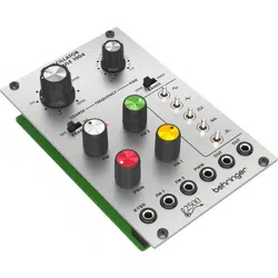
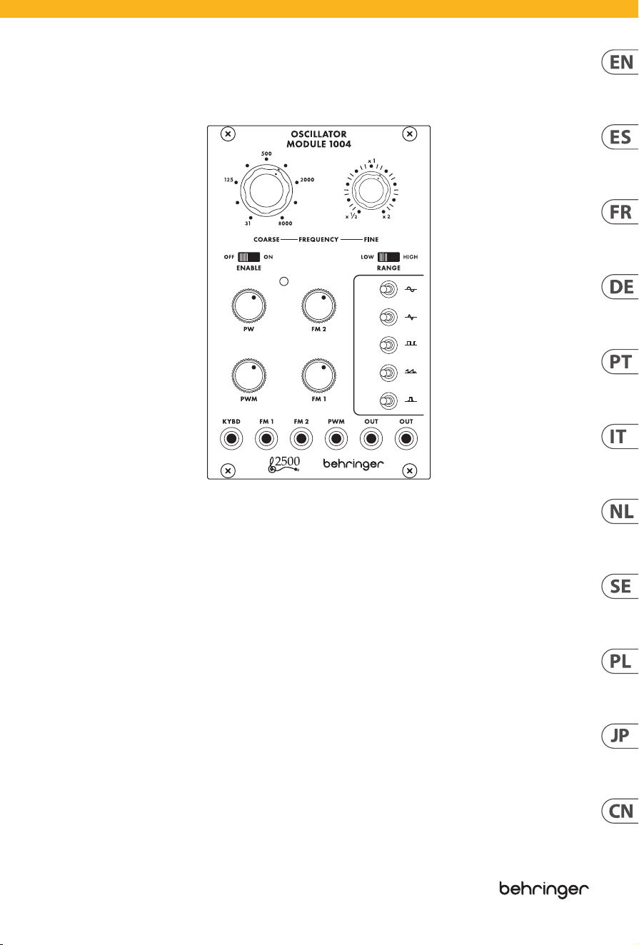
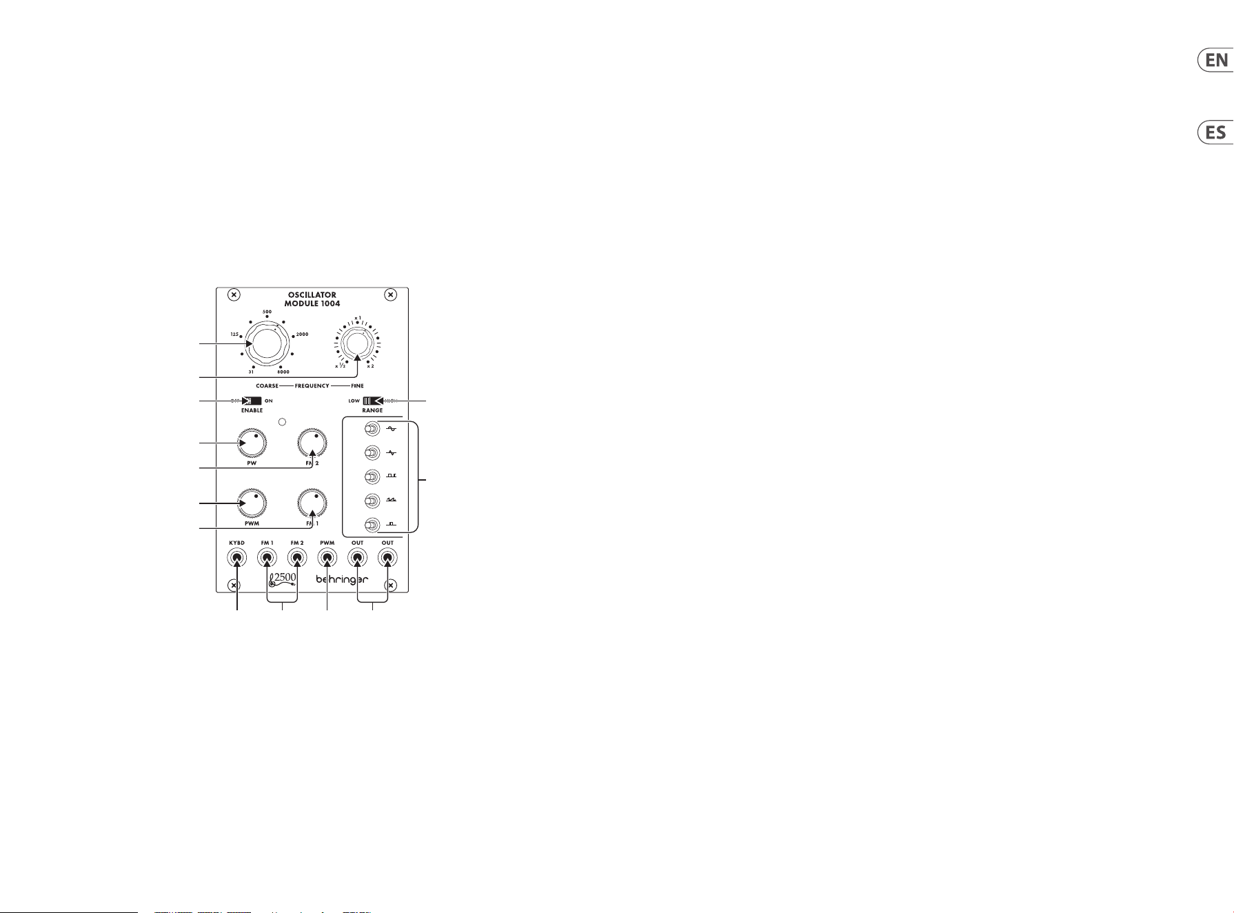
OSCILLATOR MODULE 1004 Controls
(1)
(2)
(3)
(6)
(7)
(8)
(5)
(4)
(9)
(10) (11) (12) (13)
(EN) Controls (ES) Controles
(1) COARSE FREQUENCY – Sets the frequency
from 0.03 to 32 Hz in the low (LFO) range,
or from 15.5 Hz to 16 kHz in the high (audio)
range, depending on the Fine frequency
knob setting.
(2) FINE FREQUENCY – Adjusts the frequency by
a factor of ±1 octave, potentially halving or
doubling the frequency at either extreme.
(3) ENABLE switch – Turns the oscillator on
and off.
(4) RANGE switch – Determines whether the
oscillator operates in the low (subsonic/LFO)
band or the high (audio) band.
(5) WAVEFORM switches – Engage up to 5
waveforms by moving the relevant toggle
switch to the left, or engage the inverse
waveform by moving the switch to the right.
The center position turns the waveform off.
Engaging multiple switches simultaneously
produces the average of all active waveforms.
(6) PW knob – Manually control the pulse width
for the pulse waveform.
(7) FM 2 knob – Attenuates the signal connected
to the FM 2 input.
(8) PWM knob – Adjusts the modulation depth of
the PMW control input.
(9) FM 1 knob – Attenuates the signal connected
to the FM 1 input.
(10) KYBD – Connect a keyboard or other external
frequency control via 3.5 mm TS cable.
(11) FM 1/2 – Connect external voltages to
modulate the frequency.
(12) PWM – Connect an external voltage to
modulate the pulse width.
(13) OUT – Send the oscillator signal to other
modules via 3.5 mm TS cable.
(1) COARSE FREQUENCY – Ajusta la frecuencia
de 0.03 a 32 Hz en el rango bajo (LFO), o de
15.5 Hz a 16 kHz en el rango alto (audio),
dependiendo de la configuración del botón de
frecuencia fina.
(2) FINE FREQUENCY – Ajusta la frecuencia por un
factor de ±1 octava, potencialmente dividiendo
o duplicando la frecuencia en los extremos.
(3) ENABLE switch – Enciende y apaga el oscilador.
(4) RANGE switch – Determina si el oscilador
opera en el rango bajo (subsonido/LFO) o en el
rango alto (audio).
(5) WAVEFORM switches – Activa hasta 5
formas de onda moviendo el interruptor
correspondiente hacia la izquierda, o activa
la forma de onda inversa moviendo el
interruptor hacia la derecha. La posición central
desactiva la forma de onda. Activar múltiples
interruptores simultáneamente produce el
promedio de todas las formas de onda activas.
(6) PW knob – Controla manualmente el ancho de
pulso para la forma de onda de pulso.
(7) FM 2 knob – Atenúa la señal conectada a la
entrada FM 2.
(8) PWM knob – Ajusta la profundidad de
modulación de la entrada de control PWM.
(9) FM 1 knob – Atenúa la señal conectada a la
entrada FM 1.
(10) KYBD – Conecta un teclado u otro control de
frecuencia externo a través de un cable TS de
3.5 mm.
(11) FM 1/2 – Conecta voltajes externos para
modular la frecuencia.
(12) PWM – Conecta un voltaje externo para
modular el ancho de pulso.
(13) OUT – Envía la señal del oscilador a otros
módulos a través de un cable TS de 3.5 mm.

10 11Quick Start GuideOSCILLATOR MODULE 1004
(PT) Controles(FR) Réglages (IT) Controlli(DE) Bedienelemente
(1) COARSE FREQUENCY – Define a frequência de
0,03 a 32 Hz na faixa baixa (LFO), ou de 15,5 Hz
a 16 kHz na faixa alta (áudio), dependendo da
configuração do botão de frequência fina.
(2) FINE FREQUENCY – Ajusta a frequência
por um fator de ±1 oitava, potencialmente
dividindo ou dobrando a frequência em
qualquer extremo.
(3) ENABLE switch – Liga e desliga o oscilador.
(4) RANGE switch – Determina se o oscilador
opera na banda baixa (subsonica/LFO) ou na
banda alta (áudio).
(5) WAVEFORM switches – Engaja até 5 formas
de onda movendo o interruptor de alternância
relevante para a esquerda, ou engaja a forma
de onda inversa movendo o interruptor para
a direita. A posição central desliga a forma
de onda. Engajar múltiplos interruptores
simultaneamente produz a média de todas as
formas de onda ativas.
(6) PW knob – Controla manualmente a largura
do pulso para a forma de onda de pulso.
(7) FM 2 knob – Atenua o sinal conectado à
entrada FM 2.
(8) PWM knob – Ajusta a profundidade de
modulação da entrada de controle PWM.
(9) FM 1 knob – Atenua o sinal conectado à
entrada FM 1.
(10) KYBD – Conecta um teclado ou outro controle
de frequência externo via cabo TS de 3,5 mm.
(11) FM 1/2 – Conecta tensões externas para
modular a frequência.
(12) PWM – Conecta uma tensão externa para
modular a largura do pulso.
(13) OUT – Envia o sinal do oscilador para outros
módulos via cabo TS de 3,5 mm.
(1) COARSE FREQUENCY – Définit la fréquence
de 0,03 à 32 Hz dans la plage basse (LFO), ou de
15,5 Hz à 16 kHz dans la plage haute (audio),
selon le réglage du bouton de fréquence fine.
(2) FINE FREQUENCY – Ajuste la fréquence
d’un facteur de ±1 octave, potentiellement
en divisant ou en doublant la fréquence à
chaque extrémité.
(3) ENABLE switch – Active et désactive l’oscillateur.
(4) RANGE switch – Détermine si l’oscillateur
fonctionne dans la bande basse (subsonique/
LFO) ou la bande haute (audio).
(5) WAVEFORM switches – Activez jusqu’à 5
formes d’ondes en déplaçant l’interrupteur
basculant correspondant vers la gauche, ou
activez la forme d’onde inverse en déplaçant
l’interrupteur vers la droite. La position centrale
désactive la forme d’onde. Activer plusieurs
interrupteurs simultanément produit la
moyenne de toutes les formes d’ondes actives.
(6) PW knob – Contrôle manuellement la largeur
d’impulsion pour la forme d’onde d’impulsion.
(7) FM 2 knob – Atténue le signal connecté à
l’entrée FM 2.
(8) PWM knob – Ajuste la profondeur de
modulation de l’entrée de commande PMW.
(9) FM 1 knob – Atténue le signal connecté à
l’entrée FM 1.
(10) KYBD – Connectez un clavier ou un autre contrôle
de fréquence externe via un câble TS 3,5 mm.
(11) FM 1/2 – Connectez des tensions externes pour
moduler la fréquence.
(12) PWM – Connectez une tension externe pour
moduler la largeur d’impulsion.
(13) OUT – Envoyez le signal de l’oscillateur vers
d’autres modules via un câble TS 3,5 mm.
(1) COARSE FREQUENCY – Imposta la frequenza
da 0,03 a 32 Hz nel range basso (LFO), o
da 15,5 Hz a 16 kHz nel range alto (audio),
a seconda dell’impostazione della manopola
Fine frequency.
(2) FINE FREQUENCY – Regola la frequenza
di un fattore di ±1 ottava, potenzialmente
dimezzando o raddoppiando la frequenza
agli estremi.
(3) ENABLE switch – Accende e spegne l’oscillatore.
(4) RANGE switch – Determina se l’oscillatore
opera nella banda bassa (subsonica/LFO) o nella
banda alta (audio).
(5) WAVEFORM switches – Attiva fino a 5 forme
d’onda spostando l’interruttore basculante
corrispondente a sinistra, o attiva la forma
d’onda inversa spostando l’interruttore a
destra. La posizione centrale spegne la forma
d’onda. Attivare contemporaneamente più
interruttori produce la media di tutte le forme
d’onda attive.
(6) PW knob – Controlla manualmente la
larghezza di impulso per la forma d’onda
di impulso.
(7) FM 2 knob – Attenua il segnale collegato
all’ingresso FM 2.
(8) PWM knob – Regola la profondità di
modulazione dell’ingresso di controllo PMW.
(9) FM 1 knob – Attenua il segnale collegato
all’ingresso FM 1.
(10) KYBD – Collega una tastiera o un altro
controllo di frequenza esterno tramite cavo TS
da 3,5 mm.
(11) FM 1/2 – Collega tensioni esterne per
modulare la frequenza.
(12) PWM – Collega una tensione esterna per
modulare la larghezza di impulso.
(13) OUT – Invia il segnale dell’oscillatore ad altri
moduli tramite cavo TS da 3,5 mm.
(1) COARSE FREQUENCY – Stellt die Frequenz von
0,03 bis 32 Hz im niedrigen (LFO) Bereich ein,
oder von 15,5 Hz bis 16 kHz im hohen (Audio)
Bereich, abhängig von der Einstellung des
Fein-Frequenzreglers.
(2) FINE FREQUENCY – Passt die Frequenz um
einen Faktor von ±1 Oktave an, wodurch sich
die Frequenz an jedem Extrem potenziell
halbiert oder verdoppelt.
(3) ENABLE switch – Schaltet den Oszillator ein
und aus.
(4) RANGE switch – Bestimmt, ob der Oszillator
im niedrigen (subsonischen/LFO) Bereich oder
im hohen (Audio) Bereich betrieben wird.
(5) WAVEFORM switches – Aktivieren Sie bis zu 5
Wellenformen, indem Sie den entsprechenden
Kippschalter nach links bewegen, oder aktivieren
Sie die inverse Wellenform, indem Sie den Schalter
nach rechts bewegen. Die mittlere Position
schaltet die Wellenform aus. Durch gleichzeitiges
Aktivieren mehrerer Schalter wird der
Durchschnitt aller aktiven Wellenformen erzeugt.
(6) PW knob – Manuelle Steuerung der Pulsbreite
für die Puls-Wellenform.
(7) FM 2 knob – Dämpft das Signal, das mit dem
FM 2-Eingang verbunden ist.
(8) PWM knob – Einstellung der Modulationstiefe
des PMW-Steuerungseingangs.
(9) FM 1 knob – Dämpft das Signal, das mit dem
FM 1-Eingang verbunden ist.
(10) KYBD – Verbinden Sie ein Keyboard oder eine
andere externe Frequenzsteuerung über ein
3,5-mm-TS-Kabel.
(11) FM 1/2 – Schließen Sie externe Spannungen
an, um die Frequenz zu modulieren.
(12) PWM – Schließen Sie eine externe Spannung
an, um die Pulsbreite zu modulieren.
(13) OUT – Senden Sie das Oszillatorsignal an
andere Module über ein 3,5-mm-TS-Kabel.
OSCILLATOR MODULE 1004 Controls

12 13Quick Start GuideOSCILLATOR MODULE 1004
(PL) Sterowanica
(JP) コントロール
(NL) Bediening (SE) Kontroller
(1) COARSE FREQUENCY – Ustawia częstotliwość
od 0,03 do 32 Hz w zakresie niskim (LFO),
lub od 15,5 Hz do 16 kHz w zakresie wysokim
(audio), w zależności od ustawienia gałki
Czułej częstotliwości.
(2) FINE FREQUENCY – Reguluje częstotliwość o
czynnik ±1 oktawa, potencjalnie zmniejszając
lub zwiększając częstotliwość w każdym
skrajnym przypadku.
(3) ENABLE switch – Włącza i wyłącza oscylator.
(4) RANGE switch – Określa, czy oscylator działa
w niskim (subsonicznym/LFO) paśmie, czy w
wysokim (audio) paśmie.
(5) WAVEFORM switches – Aktywuj do 5
wzorców poprzez przesunięcie odpowiedniego
przełącznika w lewo, lub aktywuj odwrotny
wzorzec przesuwając przełącznik w prawo.
Pozycja środkowa wyłącza wzorzec.
Aktywowanie wielu przełączników
jednocześnie powoduje średnią ze wszystkich
aktywnych wzorców.
(6) PW knob – Ręczne sterowanie szerokością
impulsu dla fali impulsowej.
(7) FM 2 knob – Tłumi sygnał podłączony do
wejścia FM 2.
(8) PWM knob – Reguluje głębokość modulacji
wejścia sterowania PMW.
(9) FM 1 knob – Tłumi sygnał podłączony do
wejścia FM 1.
(10) KYBD – Podłącz klawiaturę lub inne
zewnętrzne sterowanie częstotliwością za
pomocą kabla TS 3,5 mm.
(11) FM 1/2 – Podłącz zewnętrzne napięcia do
modulacji częstotliwości.
(12) PWM – Podłącz zewnętrzne napięcie do
modulacji szerokości impulsu.
(13) OUT – Wyślij sygnał oscylatora do innych
modułów za pomocą kabla TS 3,5 mm.
(1) COARSE FREQUENCY – 低 (LFO) 範囲で
は、 0.03 から 32 Hz までの周波数を設
定します。 また、Fine frequencyノブの設
定に応じて、 高 (オーディオ) 範囲で
は、 15.5 Hz から 16 kHz までの周波数を
設 定します。
(2) FINE FREQUENCY – ±1 オクターブの比 率
で周波数を調整し、両極端で周波数を
半分または倍にすることができます。
(3) ENABLE switch – 発振器をオン / オフに
します。
(4) RANGE switch – 発振器が低 (超音波 /
LFO) 帯域または高 (オーディオ) 帯域
で 動 作 するか を決 定します。
(5) WAVEFORM switches – 関連するトグル
スイッチを左に動かすことで、最大 5
つの波形を選択します。 スイッチを右
に動かすと、逆の波形が選択されま
す。 中央位置では波形がオフになりま
す。 複数のスイッチを同時に選択する
と、 アクティブなすべての波形の平均
が 生 成 され ます。
(6) PW knob – パルス波形のパルス幅を手
動 で 制 御します。
(7) FM 2 knob – FM 2 入力に接続された信
号を 減 衰させます。
(8) PWM knob – PMW 制御入力の変調深度
を調整します。
(9) FM 1 knob – FM 1 入力に接続された信
号を 減 衰させます。
(10) KYBD – キーボードまたは他の外部周
波数制御を 3.5 mm TS ケーブルで 接 続
します。
(11) FM 1/2 – 周波数を変調するために外部
電 圧 を接 続します。
(12) PWM – パルス幅を変調するために外
部 電 圧を接 続します。
(13) OUT – 発振器信号を他のモジュールに
3.5 mm TS ケーブルで 送 信します。
(1) COARSE FREQUENCY – Stelt de frequentie
in van 0,03 tot 32 Hz in het lage (LFO) bereik,
of van 15,5 Hz tot 16 kHz in het hoge (audio)
bereik, afhankelijk van de instelling van de
Fijne frequentieknop.
(2) FINE FREQUENCY – Past de frequentie aan
met een factor van ±1 octaaf, waardoor de
frequentie potentieel gehalveerd of verdubbeld
wordt aan beide uitersten.
(3) ENABLE switch – Schakelt de oscillator in en uit.
(4) RANGE switch – Bepaalt of de oscillator werkt
in het lage (subsonische/LFO) bereik of het
hoge (audio) bereik.
(5) WAVEFORM switches – Activeer tot 5
golfvormen door de relevante schakelaar naar
links te verplaatsen, of activeer de omgekeerde
golfvorm door de schakelaar naar rechts
te verplaatsen. De middenpositie schakelt
de golfvorm uit. Het gelijktijdig activeren
van meerdere schakelaars produceert het
gemiddelde van alle actieve golfvormen.
(6) PW knob – Bestuurt handmatig de
pulsbreedte voor de pulsgolfvorm.
(7) FM 2 knob – Verzwakt het signaal dat is
verbonden met de FM 2-ingang.
(8) PWM knob – Past de modulatiediepte van de
PMW-besturingsingang aan.
(9) FM 1 knob – Verzwakt het signaal dat is
verbonden met de FM 1-ingang.
(10) KYBD – Verbind een toetsenbord of andere
externe frequentiebesturing via een 3,5 mm
TS-kabel.
(11) FM 1/2 – Verbind externe voltages om de
frequentie te moduleren.
(12) PWM – Verbind een externe spanning om de
pulsbreedte te moduleren.
(13) OUT – Stuur het oscillatorsignaal naar andere
modules via een 3,5 mm TS-kabel.
(1) COARSE FREQUENCY – Ställer in frekvensen
från 0,03 till 32 Hz i det låga (LFO) området,
eller från 15,5 Hz till 16 kHz i det höga (ljud)
området, beroende på inställningen av den fina
frekvensknappen.
(2) FINE FREQUENCY – Justerar frekvensen
med en faktor av ±1 oktav, vilket potentiellt
kan halvera eller fördubbla frekvensen vid
varje extrem.
(3) ENABLE switch – Slår oscillatorn på och av.
(4) RANGE switch – Bestämmer om oscillatorn
fungerar i det låga (subsoniska/LFO) bandet
eller det höga (ljud) bandet.
(5) WAVEFORM switches – Aktivera upp till 5
vågformer genom att flytta den relevanta
växelsladden till vänster, eller aktivera
den omvända vågformen genom att flytta
omkopplaren till höger. Mittenpositionen
stänger av vågformen. Att aktivera
flera omkopplare samtidigt producerar
genomsnittet av alla aktiva vågformer.
(6) PW knob – Kontrollera manuellt pulsbredden
för pulsvågformen.
(7) FM 2 knob – Dämpar signalen som är kopplad
till FM 2-ingången.
(8) PWM knob – Justerar moduleringsdjupet för
PMW-kontrollenheten.
(9) FM 1 knob – Dämpar signalen som är kopplad
till FM 1-ingången.
(10) KYBD – Anslut ett tangentbord eller annan
extern frekvenskontroll via 3,5 mm TS-kabel.
(11) FM 1/2 – Anslut externa spänningar för att
modulera frekvensen.
(12) PWM – Anslut en extern spänning för att
modulera pulsbredden.
(13) OUT – Skicka oscillerarsignalen till andra
moduler via 3,5 mm TS-kabel.
OSCILLATOR MODULE 1004 Controls
14 15Quick Start GuideOSCILLATOR MODULE 1004
(CN) 控制
(1) COARSE FREQUENCY – 在低频 (LFO) 范围
内设置频率从 0.03 至 32 Hz 兹, 或在高
频 (音频) 范围内从 15.5 Hz 兹至 16 kHz,
取决于 Fine 频率旋钮的设置。
(2) FINE FREQUENCY – 通过±1个八度的因子
调整频率, 可能在任一极端减半或加
倍频率。
(3) ENABLE switch – 打开或关闭振荡器。
(4) RANGE switch – 确定振荡器在低频
(次声 / LFO) 频段还是高频 (音频) 频段
操作。
(5) WAVEFORM switches – 通过将相关切换
开关向左移动来使最多 5 种波形参与,
或通过将开关向右移动使反向波形参
与。 中间位置关闭波形。 同时激活多个
开关会产生所有活动波形的平均值。
(6) PW knob – 手动控制脉冲波形的脉冲
宽度。
(7) FM 2 knob – 衰减连接到 FM 2 输入的
信号。
(8) PWM knob - 调整 PMW 控制输入的调
制深度。
(9) FM 1 knob - 衰减连接到 FM 1 输入的
信号。
(10) KYBD - 通过 3.5 mm TS 电缆连接键盘
或其他外部频率控制。
(11) FM 1/2 - 连接外部电压以调制频率。
(12) PWM - 连接外部电压以调制脉冲宽度。
(13) OUT - 通过 3.5 mm TS 电缆将振荡器信
号发送到其他模块。
OSCILLATOR MODULE 1004 Controls
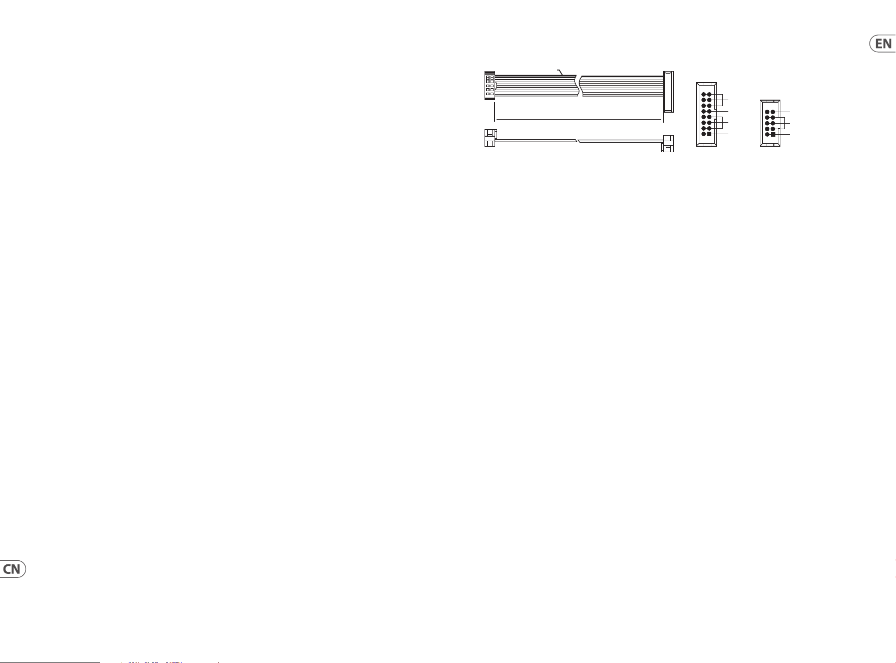
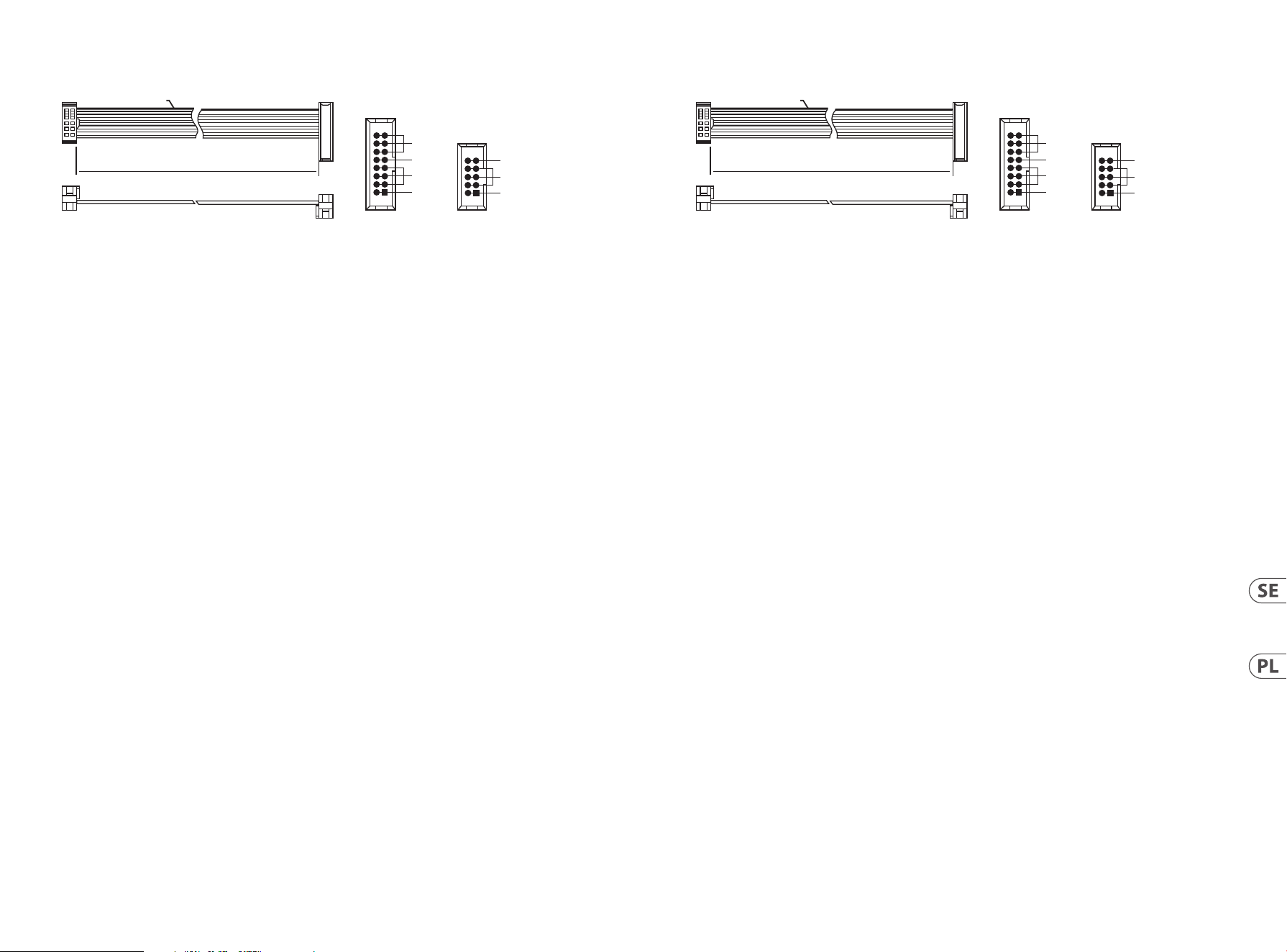
Power Connection
The OSCILLATOR MODULE 1004 module comes with the required power cable for connecting to a standard Eurorack power
supply system. Follow these steps to connect power to the module. It is easier to make these connections before the
module has been mounted into a rack case.
1. Turn the power supply or rack case power off and disconnect the power cable.
2. Insert the 16-pin connector on the power cable into the socket on the power supply or rack case. The connector has a tab
that will align with the gap in the socket, so it cannot be inserted incorrectly. If the power supply does not have a keyed
socket, be sure to orient pin 1 (-12 V) with the red stripe on the cable.
3. Insert the 10-pin connector into the socket on the back of the module. The connector has a tab that will align with the
socket for correct orientation.
4. After both ends of the power cable have been securely attached, you may mount the module in a case and turn on the
power supply.
Installation
The necessary screws are included with the module for mounting in a Eurorack case. Connect the power cable
before mounting.
Depending on the rack case, there may be a series of fixed holes spaced 2 HP apart along the length of the case, or a track
that allows individual threaded plates to slide along the length of the case. The free-moving threaded plates allow precise
positioning of the module, but each plate should be positioned in the approximate relation to the mounting holes in your
module before attaching the screws.
Hold the module against the Eurorack rails so that each of the mounting holes are aligned with a threaded rail or threaded
plate. Attach the screws part way to start, which will allow small adjustments to the positioning while you get them all
aligned. After the final position has been established, tighten the screws down.
HOT USED
Red Stripe
200 mm ± 10
15 16
21
P2P1
2
10
9
1
Connect end P1 to the module socket
Connect end P2 to the power supply
+ 12V
- 12V
GROUND
+ 12V
- 12V
GROUND
16 17Quick Start GuideOSCILLATOR MODULE 1004
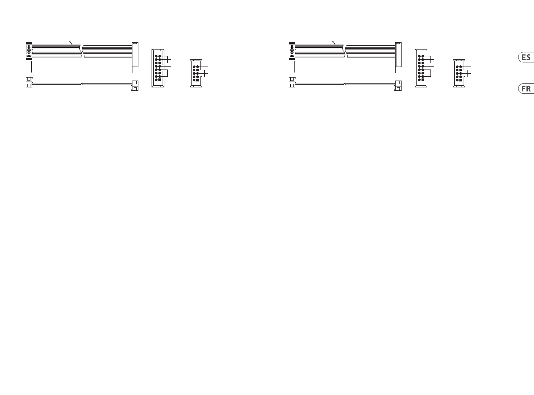
Conexión Eléctrica
El módulo OSCILLATOR MODULE 1004 viene con el cable de alimentación necesario para conectarse a un sistema de
suministro de energía Eurorack estándar. Sigue estos pasos para conectar la energía al módulo. Es más fácil realizar estas
conexiones antes de que el módulo se haya montado en un estuche de rack.
1. Apaga la fuente de alimentación o el estuche de rack y desconecta el cable de alimentación.
2. Inserta el conector de 16 pines del cable de alimentación en el enchufe de la fuente de alimentación o del estuche
de rack. El conector tiene una pestaña que se alineará con el espacio en el enchufe, por lo que no se puede insertar
incorrectamente. Si la fuente de alimentación no tiene un enchufe con llave, asegúrate de orientar el pin 1 (-12 V) con la
franja roja en el cable.
3. Inserta el conector de 10 pines en el enchufe en la parte posterior del módulo. El conector tiene una pestaña que se
alineará con el enchufe para una orientación correcta.
4. Después de que ambos extremos del cable de alimentación hayan sido conectados de forma segura, puedes montar el
módulo en un estuche y encender la fuente de alimentación.
Installation
Los tornillos necesarios están incluidos con el módulo para el montaje en un estuche Eurorack. Conecta el cable de
alimentación antes de montarlo.
Dependiendo del estuche de rack, puede haber una serie de agujeros fijos espaciados 2 HP de distancia a lo largo del
estuche, o una pista que permita que las placas roscadas individuales se deslicen a lo largo del estuche. Las placas roscadas
móviles permiten un posicionamiento preciso del módulo, pero cada placa debe colocarse en relación aproximada con los
agujeros de montaje en tu módulo antes de fijar los tornillos.
Sujeta el módulo contra los rieles Eurorack de modo que cada uno de los agujeros de montaje estén alineados con un riel
roscado o una placa roscada. Coloca los tornillos parcialmente para empezar, lo que permitirá pequeños ajustes en el
posicionamiento mientras los alineas todos. Después de que se haya establecido la posición final, aprieta los tornillos.
HOT USED
Red Stripe
200 mm ± 10
15 16
21
P2P1
2
10
9
1
Connect end P1 to the module socket
Connect end P2 to the power supply
+ 12V
- 12V
GROUND
+ 12V
- 12V
GROUND
Connexion Électrique
Le module OSCILLATOR MODULE 1004 est livré avec le câble d’alimentation nécessaire pour se connecter à un système
d’alimentation standard Eurorack. Suivez ces étapes pour connecter l’alimentation au module. Il est plus facile de réaliser
ces connexions avant que le module ne soit monté dans un boîtier de rack.
1. Éteignez l’alimentation électrique ou le boîtier de rack et débranchez le câble d’alimentation.
2. Insérez le connecteur à 16 broches du câble d’alimentation dans la prise de l’alimentation électrique ou du boîtier de
rack. Le connecteur a une languette qui s’alignera avec l’espace dans la prise, il ne peut donc pas être inséré de manière
incorrecte. Si l’alimentation électrique n’a pas de prise à clé, assurez-vous d’orienter la broche 1 (-12 V) avec la bande
rouge sur le câble.
3. Insérez le connecteur à 10 broches dans la prise à l’arrière du module. Le connecteur a une languette qui s’alignera avec
la prise pour une orientation correcte.
4. Une fois que les deux extrémités du câble d’alimentation ont été solidement fixées, vous pouvez monter le module dans
un boîtier et allumer l’alimentation électrique.
Installation
Les vis nécessaires sont incluses avec le module pour le montage dans un boîtier Eurorack. Connectez le câble
d’alimentation avant le montage.
En fonction du boîtier de rack, il peut y avoir une série de trous fixes espacés de 2 HP le long de la longueur du boîtier,
ou une piste qui permet à des plaques filetées individuelles de glisser le long de la longueur du boîtier. Les plaques
filetées mobiles permettent un positionnement précis du module, mais chaque plaque doit être positionnée de manière
approximative par rapport aux trous de montage de votre module avant de fixer les vis.
Maintenez le module contre les rails Eurorack de manière à ce que chacun des trous de montage soit aligné avec un rail
fileté ou une plaque filetée. Fixez les vis partiellement pour commencer, ce qui permettra des ajustements mineurs de
positionnement pendant que vous les alignez tous. Après que la position finale a été établie, serrez les vis.
HOT USED
Red Stripe
200 mm ± 10
15 16
21
P2P1
2
10
9
1
Connect end P1 to the module socket
Connect end P2 to the power supply
+ 12V
- 12V
GROUND
+ 12V
- 12V
GROUND
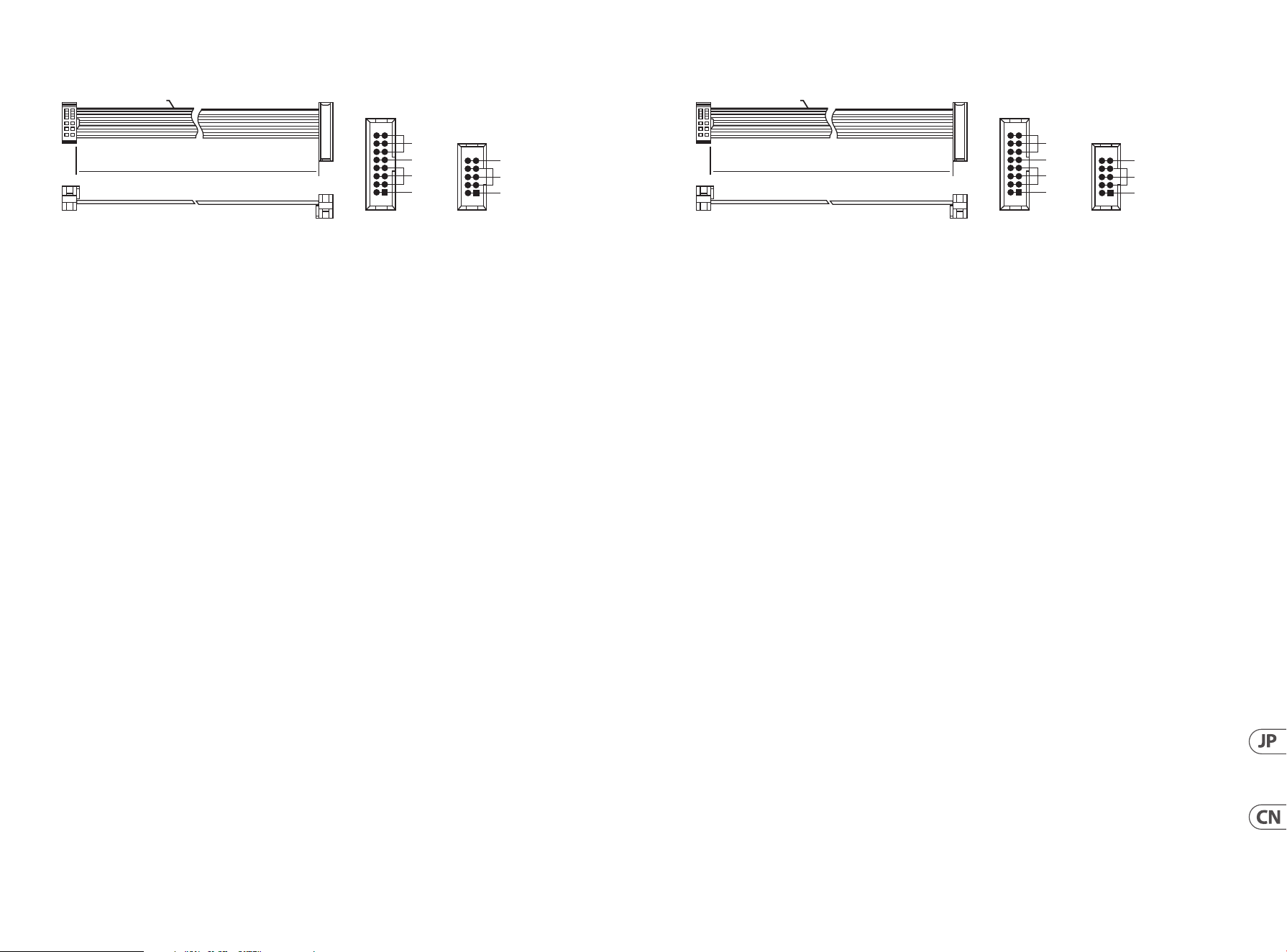
18 19Quick Start GuideOSCILLATOR MODULE 1004
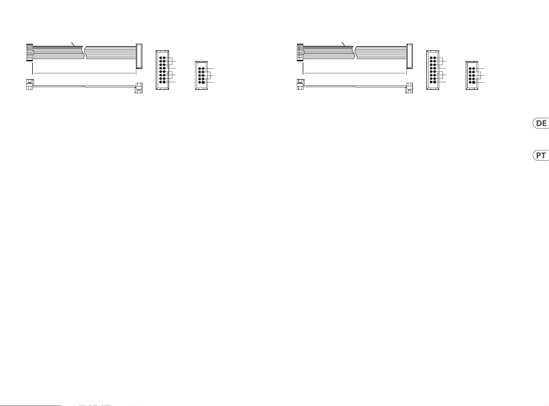
Netzanschluss
Das Modul OSCILLATOR MODULE 1004 wird mit dem erforderlichen Stromkabel geliefert, um es mit einem Standard-
Eurorack-Stromversorgungssystem zu verbinden. Befolgen Sie diese Schritte, um das Modul mit Strom zu versorgen. Es ist
einfacher, diese Verbindungen herzustellen, bevor das Modul in ein Rackgehäuse montiert wurde.
1. Schalten Sie die Stromversorgung oder die Stromversorgung des Rackgehäuses aus und trennen Sie das Stromkabel.
2. Stecken Sie den 16-poligen Stecker des Stromkabels in die Buchse der Stromversorgung oder des Rackgehäuses. Der
Stecker hat eine Lasche, die sich mit der Lücke in der Buchse ausrichtet, sodass er nicht falsch eingesteckt werden kann.
Wenn die Stromversorgung keine verriegelte Buchse hat, achten Sie darauf, Pin 1 (-12 V) mit dem roten Streifen auf dem
Kabel auszurichten.
3. Stecken Sie den 10-poligen Stecker in die Buchse auf der Rückseite des Moduls. Der Stecker hat eine Lasche, die sich mit
der Buchse zur korrekten Ausrichtung ausrichtet.
4. Nachdem beide Enden des Stromkabels sicher befestigt wurden, können Sie das Modul in einem Gehäuse montieren und
die Stromversorgung einschalten.
Installation
Die erforderlichen Schrauben sind im Lieferumfang des Moduls für die Montage in einem Eurorack-Gehäuse enthalten.
Schließen Sie das Stromkabel vor der Montage an.
Je nach Rackgehäuse können entweder eine Reihe fester Löcher entlang der Länge des Gehäuses angeordnet sein, die
jeweils 2 HP voneinander entfernt sind, oder eine Schiene, die es einzelnen Gewindeplatten ermöglicht, entlang der Länge
des Gehäuses zu gleiten. Die frei beweglichen Gewindeplatten ermöglichen eine präzise Positionierung des Moduls, aber
jede Platte sollte in etwa zum Verhältnis zu den Montagelöchern in Ihrem Modul positioniert werden, bevor die Schrauben
angebracht werden.
Halten Sie das Modul gegen die Eurorack-Schienen, sodass jedes der Montagelöcher mit einer Gewindeschiene oder einer
Gewindeplatte ausgerichtet ist. Bringen Sie die Schrauben teilweise an, um kleinere Anpassungen an der Positionierung
vorzunehmen, während Sie sie alle ausrichten. Nachdem die endgültige Position festgelegt wurde, ziehen Sie die
Schrauben fest.
HOT USED
Red Stripe
200 mm ± 10
15 16
21
P2P1
2
10
9
1
Connect end P1 to the module socket
Connect end P2 to the power supply
+ 12V
- 12V
GROUND
+ 12V
- 12V
GROUND
Conexão de Força
O módulo OSCILLATOR MODULE 1004 vem com o cabo de alimentação necessário para conectar a um sistema de
alimentação padrão Eurorack. Siga estes passos para conectar a energia ao módulo. É mais fácil fazer essas conexões antes
de o módulo ser montado em um case de rack.
1. Desligue a fonte de alimentação ou o power case e desconecte o cabo de energia.
2. Insira o conector de 16 pinos do cabo de energia na tomada da fonte de alimentação ou do case de rack. O conector
possui uma aba que se alinhará com a lacuna na tomada, para que não possa ser inserido incorretamente. Se a fonte de
alimentação não tiver uma tomada com chave, certifique-se de orientar o pino 1 (-12 V) com a faixa vermelha no cabo.
3. Insira o conector de 10 pinos na tomada na parte de trás do módulo. O conector possui uma aba que se alinhará com a
tomada para orientação correta.
4. Após ambas as extremidades do cabo de energia estarem firmemente conectadas, você pode montar o módulo em um
case e ligar a fonte de alimentação.
Installation
Os parafusos necessários estão incluídos com o módulo para montagem em um case Eurorack. Conecte o cabo de
alimentação antes da montagem.
Dependendo do case de rack, pode haver uma série de furos fixos espaçados 2 HP de distância ao longo do comprimento
do case, ou uma trilha que permite que placas roscadas individuais deslizem ao longo do comprimento do case. As placas
roscadas móveis permitem um posicionamento preciso do módulo, mas cada placa deve ser posicionada em relação
aproximada aos furos de montagem em seu módulo antes de fixar os parafusos.
Segure o módulo contra os trilhos Eurorack para que cada um dos furos de montagem esteja alinhado com um trilho ou
placa roscada. Prenda os parafusos parcialmente para começar, o que permitirá pequenos ajustes no posicionamento
enquanto você os alinha. Após a posição final ser estabelecida, aperte os parafusos.
HOT USED
Red Stripe
200 mm ± 10
15 16
21
P2P1
2
10
9
1
Connect end P1 to the module socket
Connect end P2 to the power supply
+ 12V
- 12V
GROUND
+ 12V
- 12V
GROUND
20 21Quick Start GuideOSCILLATOR MODULE 1004
Connessione di Alimentazione
Il modulo OSCILLATOR MODULE 1004 viene fornito con il cavo di alimentazione necessario per il collegamento a un sistema
di alimentazione Eurorack standard. Seguire questi passaggi per collegare l’alimentazione al modulo. È più facile effettuare
questi collegamenti prima che il modulo sia stato montato in un case rack.
1. Spegnere l’alimentatore o il case del rack e scollegare il cavo di alimentazione.
2. Inserire il connettore a 16 pin del cavo di alimentazione nella presa sull’alimentatore o sulla custodia del rack. Il
connettore ha una linguetta che si allineerà con lo spazio nella presa, quindi non può essere inserito in modo errato.
Se l’alimentatore non dispone di una presa con chiave, assicurarsi di orientare il pin 1 (-12 V) con la striscia rossa sul cavo.
3. Inserire il connettore a 10 pin nella presa sul retro del modulo. Il connettore ha una linguetta che si allineerà con la presa
per un corretto orientamento.
4. Dopo che entrambe le estremità del cavo di alimentazione sono state fissate saldamente, è possibile montare il modulo
in una custodia e accendere l’alimentatore.
Installazione
Le viti necessarie sono incluse con il modulo per il montaggio in una custodia Eurorack. Collegare il cavo di alimentazione
prima del montaggio.
A seconda del case del rack, potrebbero esserci una serie di fori fissi distanziati di 2 HP l’uno dall’altro lungo la lunghezza
del case, o un binario che consente alle singole piastre filettate di scorrere lungo la lunghezza del case. Le piastre filettate
a movimento libero consentono un posizionamento preciso del modulo, ma ciascuna piastra deve essere posizionata in
relazione approssimativa con i fori di montaggio nel modulo prima di fissare le viti.
Tenere il modulo contro le guide Eurorack in modo che ciascuno dei fori di montaggio sia allineato con una guida filettata o
una piastra filettata. Attacca le viti in parte per iniziare, il che consentirà piccoli aggiustamenti al posizionamento mentre le
fai allineare tutte. Dopo aver stabilito la posizione finale, serrare le viti.
HOT USED
Red Stripe
200 mm ± 10
15 16
21
P2P1
2
10
9
1
Connect end P1 to the module socket
Connect end P2 to the power supply
+ 12V
- 12V
GROUND
+ 12V
- 12V
GROUND
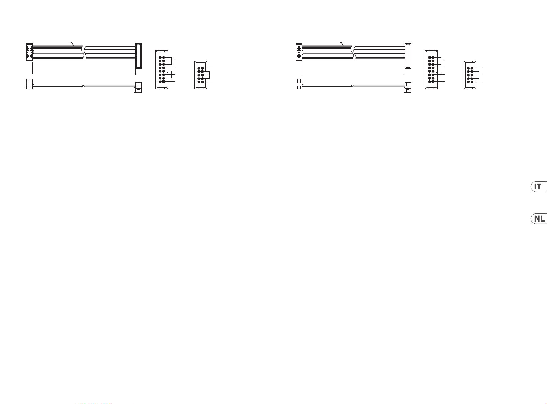
Stroomaansluiting
Het OSCILLATOR MODULE 1004-module wordt geleverd met het benodigde stroomkabel voor aansluiting op een standaard
Eurorack-voedingssysteem. Volg deze stappen om de stroom aan te sluiten op het module. Het is gemakkelijker om deze
verbindingen te maken voordat het module in een rackbehuizing is gemonteerd.
1. Schakel de stroomvoorziening of de stroomvoorziening van het rack uit en koppel de stroomkabel los.
2. Steek de 16-pins connector van de stroomkabel in de socket van de voeding of het rack. De connector heeft een tab die
zal uitlijnen met de opening in de socket, zodat hij niet verkeerd kan worden ingevoegd. Als de voeding geen gekeerde
socket heeft, zorg er dan voor dat pin 1 (-12 V) wordt georiënteerd met de rode streep op de kabel.
3. Steek de 10-pins connector in de socket aan de achterkant van het module. De connector heeft een tabblad dat zal
uitlijnen met de socket voor de juiste oriëntatie.
4. Nadat beide uiteinden van de stroomkabel stevig zijn bevestigd, kunt u het module in een behuizing monteren en de
stroom inschakelen.
Installatie
De benodigde schroeven zijn inbegrepen bij het module voor montage in een Eurorack-behuizing. Sluit de stroomkabel aan
voordat u gaat monteren.
Afhankelijk van het rack, kunnen er een reeks vaste gaten zijn met een tussenruimte van 2 HP langs de lengte van het
rack, of een spoor waarmee individuele draadplaten langs de lengte van het rack kunnen schuiven. De vrij bewegende
draadplaten zorgen voor een nauwkeurige positionering van het module, maar elke plaat moet in de benaderende
verhouding tot de montagegaten in uw module worden geplaatst voordat u de schroeven bevestigt.
Houd het module tegen de Eurorack-rails zodat elk van de montagegaten is uitgelijnd met een draad of draadplaat.
Bevestig de schroeven gedeeltelijk om te beginnen, zodat kleine aanpassingen aan de positionering mogelijk zijn terwijl u
ze allemaal uitlijnt. Nadat de uiteindelijke positie is vastgesteld, draai de schroeven aan.
HOT USED
Red Stripe
200 mm ± 10
15 16
21
P2P1
2
10
9
1
Connect end P1 to the module socket
Connect end P2 to the power supply
+ 12V
- 12V
GROUND
+ 12V
- 12V
GROUND
22 23Quick Start GuideOSCILLATOR MODULE 1004
Strömanslutning
Modulen OSCILLATOR MODULE 1004 levereras med den nödvändiga strömkabeln för anslutning till ett standard Eurorack-
strömförsörjningssystem. Följ dessa steg för att ansluta strömmen till modulen. Det är lättare att göra dessa anslutningar
innan modulen har monterats in i ett rackfodral.
1. Stäng av strömförsörjningen eller rackfodralets ström och koppla loss strömkabeln.
2. Sätt in den 16-pinskontakten på strömkabeln i sockeln på strömförsörjningen eller rackfodralet. Kontakten har en flik
som kommer att anpassas till glappet i sockeln, så den kan inte sättas in felaktigt. Om strömförsörjningen inte har en
nyckelsockel, se till att orientera stift 1 (-12 V) med den röda ränderna på kabeln.
3. Sätt in den 10-pinskontakten i sockeln på baksidan av modulen. Kontakten har en flik som kommer att anpassas till
sockeln för korrekt orientering.
4. När båda ändarna av strömkabeln har säkrats kan du montera modulen i ett fodral och slå på strömförsörjningen.
Installation
De nödvändiga skruvarna medföljer modulen för montering i ett Eurorack-fodral. Anslut strömkabeln innan montering.
Beroende på rackfodralet kan det finnas en serie fasta hål med 2 HP avstånd längs fodralets längd, eller en spår som
tillåter individuella gängade plattor att glida längs fodralets längd. De rörliga gängade plattorna tillåter exakt placering av
modulen, men varje platta bör placeras i ungefärlig relation till monteringshålen i din modul innan du fäster skruvarna.
Håll modulen mot Eurorack-rälsarna så att varje monteringshål är justerat med en gängad räls eller gängad platta.
Fäst skruvarna delvis för att börja, vilket kommer att möjliggöra små justeringar av positioneringen medan du får dem alla
justerade. Efter att den slutliga positionen har etablerats, dra åt skruvarna.
HOT USED
Red Stripe
200 mm ± 10
15 16
21
P2P1
2
10
9
1
Connect end P1 to the module socket
Connect end P2 to the power supply
+ 12V
- 12V
GROUND
+ 12V
- 12V
GROUND
Podłączenie Zasilania
Moduł OSCILLATOR MODULE 1004 jest dostarczany z wymaganym kablem zasilającym do podłączenia do standardowego
systemu zasilania Eurorack. Wykonaj poniższe czynności, aby podłączyć zasilanie do modułu. Łatwiej jest wykonać te
połączenia przed zamontowaniem modułu w obudowie rack.
1. Wyłącz zasilacz lub obudowę szafy i odłącz kabel zasilający.
2. Włóż 16-stykowe złącze przewodu zasilającego do gniazda w zasilaczu lub w szafie typu rack. Złącze ma wypustkę, która
będzie wyrównana ze szczeliną w gnieździe, więc nie można jej nieprawidłowo włożyć. Jeśli zasilacz nie ma gniazda z
kluczem, należy zorientować styk 1 (-12 V) z czerwonym paskiem na kablu.
3. Włóż 10-pinowe złącze do gniazda z tyłu modułu. Złącze ma wypustkę, która będzie wyrównana z gniazdem, aby
zapewnić prawidłową orientację.
4. Po solidnym zamocowaniu obu końców kabla zasilającego można zamontować moduł w obudowie i włączyć zasilacz.
Instalacja
Do modułu dołączone są niezbędne śruby do montażu w skrzynce Eurorack. Podłącz kabel zasilający przed montażem.
W zależności od obudowy szafy może występować szereg stałych otworów rozmieszczonych w odstępach 2 HP na całej
długości obudowy lub prowadnica, która umożliwia przesuwanie pojedynczych gwintowanych płyt wzdłuż całej obudowy.
Swobodnie poruszające się gwintowane płytki umożliwiają precyzyjne ustawienie modułu, ale każda płyta powinna być
ustawiona w przybliżeniu w stosunku do otworów montażowych w module przed przykręceniem śrub.
Przytrzymaj moduł na szynach Eurorack, tak aby każdy z otworów montażowych był wyrównany z szyną gwintowaną lub
płytą gwintowaną. Wkręć śruby częściowo, aby rozpocząć, co pozwoli na drobne korekty położenia, gdy wszystkie zostaną
wyrównane. Po ustaleniu ostatecznego położenia dokręcić śruby.
HOT USED
Red Stripe
200 mm ± 10
15 16
21
P2P1
2
10
9
1
Connect end P1 to the module socket
Connect end P2 to the power supply
+ 12V
- 12V
GROUND
+ 12V
- 12V
GROUND
24 25Quick Start GuideOSCILLATOR MODULE 1004
電源接続
OSCILLATOR MODULE 1004 モジュールには、標準の Eurorack 電源システムに接続するために必要な電源ケ
ーブルが付属しています。モジュールに電源を接続する手順に従ってください。ラックケースにモジュ
ールを取り付ける前にこれらの接続を行う方が簡単です。
1. 電源装置またはラックケースの電源を切り、電源ケーブルを外します。
2. 電 源 ケーブル の 16 ピンコネクタを電 源装置またはラックケースのソケットに挿入します。コネクタに
はソケットの隙間に合うタブが付いているので、間違って挿入することはできません。電源装置に
キー付きソケットがない場合は、必ずピン 1 (-12 V) をケーブルの赤いストライプに向けてください。
3. モジュールの背面にあるソケットに 10 ピンコネクタを挿入します。 コネクタには、正しい方向に向
け て ソケ ットと位 置 合 わ せ するタブが ありま す。
4. 電源ケーブルの両端をしっかりと取り付けたら、モジュールをケースに取り付けて電源を入れます。
インストール
ユーロラックケースに取り付けるために必要なネジはモジュールに含まれています。取り付ける前に電
源 ケーブル を接 続してください 。
ラックケースによっては 、ケースの 長さに 沿 って
2 HP
間隔で配置された一連の固定穴、または個々のネ
ジ付きプレートをケースの長さに沿ってスライドできるトラックが 存 在する場合があります。自由に動く
ネジ付きプレートにより、モジュールを正確に配置できますが、ネジを取り付ける前に、各プレートをモ
ジュールの取り付け穴とほぼ同じ位置に配置する必要があります。
モジュールを
Eurorack
レールに押し付けて、各取り付け穴がネジ付きレールまたはネジ付きプレートと
揃うようにします。開始の途中でネジを取り付けます。これにより、すべてのネジを揃えながら、位置を
微 調 整 できます。最 終 位 置 が 決まったら、ネジ を 締 めます。
HOT USED
Red Stripe
200 mm ± 10
15 16
21
P2P1
2
10
9
1
Connect end P1 to the module socket
Connect end P2 to the power supply
+ 12V
- 12V
GROUND
+ 12V
- 12V
GROUND
电源连接
OSCILLATOR MODULE 1004 模块配备了连接到标准 Eurorack 电源系统所需的电源电缆。 按照以下步骤连接
模块的电源。 在将模块安装到机架盒之前进行这些连接更容易。
1. 关闭电源或机架箱电源, 并拔下电源电缆。
2. 将电源电缆上的 16 针连接器插入电源或机架箱上的插座。 连接器带有一个标签, 可以与插座中的
间隙对齐, 因此无法插入错误。 如果电源没有带钥匙的插座, 请确保将引脚 1 (-12 V) 与电缆上的红色
条纹对齐。
3. 将 10 针连接器插入模块背面的插座中。 连接器带有一个标签, 可以与插座正确对齐。
4. 在电源电缆的两端都已安全连接后, 您可以将模块安装在机箱中并打开电源。
安装
模块附带了安装在 Eurorack 机箱中所需的螺丝。在安装之前连接电源电缆。
根据机架箱的不同, 机箱长度上可能会有一系列间隔为 2 HP 的固定孔, 或者一个轨道, 允许单独的螺纹
板沿着机箱的长度滑动。 自由移动的螺纹板可以精确定位模块, 但是每个板在连接螺丝之前应该大致
放置在您模块的安装孔的位置。
将模块压在 Eurorack 导轨上, 使每个安装孔都与一个螺纹导轨或螺纹板对齐。 开始时部分地固定螺
丝, 这样可以在您将它们全部对齐时允许位置的微小调整。 确定最终位置后, 将螺丝拧紧。
HOT USED
Red Stripe
200 mm ± 10
15 16
21
P2P1
2
10
9
1
Connect end P1 to the module socket
Connect end P2 to the power supply
+ 12V
- 12V
GROUND
+ 12V
- 12V
GROUND
26 27Quick Start GuideOSCILLATOR MODULE 1004
Specifications
Inputs
FM 1/2
Type 2 x 3.5 mm TS jacks
Impedance 50 kΩ, unbalanced
Max input level 10 V, 1 V/octave
Keyboard
Type 3.5 mm TS jack
Impedance 50 kΩ, unbalanced
Max input level 10 V, 1 V/octave
PWM
Type 3.5 mm TS jack
Impedance 50 kΩ, unbalanced
CV range ±10 V, 10% per volt
Outputs
Out
Type 2 x 3.5 mm TS jacks
Impedance 1 kΩ, unbalanced
Max output level 10 V p-p
Controls
Coarse Sets oscillator frequency
(8 octave range)
Fine Oscillator fine adjustment
(±1 octave)
Range Select LFO
(0.06 Hz – 16 Hz)
or audio band
(31 Hz – 8 kHz)
Enable Oscillator on/off
PW Pulse width adjustment
(5% – 95%)
PWM Modulation depth
adjustment
(-∞ to unity gain)
FM 1/2 Attenuate FM inputs
(-∞ to unity gain)
Waveform switches Select up to 5 waveforms
(sine, tri, square,
saw, pulse)
Power
Power supply Eurorack
Current draw 60 mA (+12 V),
50 mA (-12 V)
Physical
Dimensions 46 x 81 x 129 mm
(1.8 x 3.2 x 5.1")
Rack units 16 HP
Weight 0.17 kg (0.37 lbs)
技术参数
技术参数
FM 1/2
类型
2 x 3.5 mm TS 插孔
阻抗
50 kΩ, 不平衡
最大输入电平
10 V, 1 V/octave
键盘
类型
3.5 mm TS 插孔
阻抗
50 kΩ, 不平衡
最大输入电平
10 V, 1 V/octave
PWM
类型
3.5 mm TS 插孔
阻抗
50 kΩ, 不平衡
最大输入电平
±10 V, 每伏 10%
输出
输出
类型
2 x 3.5 mm TS 插孔
阻抗
1 kΩ, 不平衡
最大输入电平
10 V p-p
控制
粗调 设置振荡器频率
(8 个八度范 围 )
细调
振荡器微调
(±1 octave)
范围
选择 LFO
(0.06 Hz – 16 Hz)
或音频带宽
(31 Hz – 8 kHz)
启用
振荡器开 / 关
PW 脉宽调节 (5% – 95%)
PWM 调制深度调节
(-∞ 至单位增益)
FM 1/2 衰减 FM 输入
(-∞ 至单位增益)
波形开关
选择最多 5 种波形
(正弦波、 三角波、
方波、 锯齿波、 脉冲)
电源
电源供应
Eurorack
电流消耗
60 mA (+12 V),
50 mA (-12 V)
物理
尺寸
46 x 81 x 129 mm
(1.8 x 3.2 x 5.1")
机架单位
16 HP
重量
0.17 kg (0.37 lbs)
28 29Quick Start GuideOSCILLATOR MODULE 1004
FEDERAL COMMUNICATIONS
COMMISSION COMPLIANCE
INFORMATION
Behringer
OSCILLATOR MODULE 1004
Responsible Party Name: Music Tribe Commercial NV Inc.
Address: 122 E. 42nd St.1,
8th Floor NY, NY 10168,
United States
Email Address: [email protected]
OSCILLATOR MODULE 1004
This equipment has been tested and found to comply with
the limits for a Class B digital device, pursuant to part
15 of the FCC Rules. These limits are designed to provide
reasonable protection against harmful interference in
a residential installation. This equipment generates,
uses and can radiate radio frequency energy and, if not installed
and used in accordance with the instructions, may cause harmful
interference to radio communications. However, there is no
guarantee that interference will not occur in a particular installation.
If this equipment does cause harmful interference to radio or
television reception, which can be determined by turning the
equipment off and on, the user is encouraged to try to correct the
interference by one or more of the following measures:
• • Reorient or relocate the receiving antenna.
• • Increase the separation between the equipment and receiver.
• • Connect the equipment into an outlet on a circuit different
from that to which the receiver is connected.
• • Consult the dealer or an experienced
radio/TV technician for help.
This equipment complies with Part 15 of the FCC rules. Operation
is subject to the following two conditions:
(1) this device may not cause harmful interference, and
(2) this device must accept any interference received, including
interference that may cause undesired operation.
Important information:
Changes or modifications to the equipment not expressly
approved by Music Tribe can void the user’s authority to
use the equipment.
Hereby, Music Tribe declares that this product is in compliance
with Directive 2014/30/EU, Directive 2011/65/EU and Amendment
2015/863/EU, Directive 2012/19/EU, Regulation 519/2012 REACH SVHC
and Directive 1907/2006/EC.
Full text of EU DoC is available at https://community.musictribe.com/
EU Representative: Music Tribe Brands DK A/S
Address: Gammel Strand 44, DK-1202 København K, Denmark
UK Representative: Music Tribe Brands UK Ltd.
Address: 8
th
Floor, 20 Farringdon Street London EC4A 4AB,
United Kingdom
Correct disposal of this product: This symbol
indicates that this product must not be disposed
of with household waste, according to the WEEE
Directive (2012/19/EU) and your national law.
This product should be taken to a collection center
licensed for the recycling of waste electrical and
electronic equipment (EEE). The mishandling of this type of
waste could have a possible negative impact on the environment
and human health due to potentially hazardous substances
that are generally associated with EEE. At the same time, your
cooperation in the correct disposal of this product will contribute
to the efficient use of natural resources. For more information
about where you can take your waste equipment for recycling,
please contact your local city office, or your household waste
collection service.
型 号: OSCILLATOR MODULE 1004 合成器与采样器
制造商: Music Tribe Commercial FZE –
Made in China 中国制造
CAN ICES–003 (B)/NMB–003 (B)

We Hear You