Quick Start Guide
2600-VCO
Legendary Analog VCO Module for Eurorack
V 3.0
2 2600-VCO Quick Start Guide 3
7. Verwenden Sie nur
spezizierte Wagen,
Ständer, Stative,
Halterungen oder Tische.
Achten Sie darauf, beim
Bewegen der Wagen-
Geräte-Kombination ein
Umkippen zu vermeiden.
8. Vermeiden Sie die Installation in beengten Räumen
wie Bücherregalen.
9. Nicht in der Nähe von oenen Flammenquellen
platzieren, wie brennende Kerzen.
10. Betriebstemperaturbereich von 5° bis 45°C
(41° bis 113°F).
HAFTUNGSAUSSCHLUSS
Music Tribe übernimmt keine Haftung für Verluste,
die Personen entstanden sind, die sich ganz oder
teilweise auf hier enthaltene Beschreibungen,
Fotos oder Aussagen verlassen haben. Technische Daten,
Erscheinungsbild und andere Informationen können
ohne vorherige Ankündigung geändert werden. Alle
Warenzeichen sind Eigentum der jeweiligen Inhaber.
Midas, Klark Teknik, Lab Gruppen, Lake, Tannoy,
Turbosound, TC Electronic, TC Helicon, Behringer, Bugera,
Aston Microphones und Coolaudio sind Warenzeichen
oder eingetragene Warenzeichen der Music Tribe Global
Brands Ltd. © Music Tribe Global Brands Ltd. 2024 Alle
Rechte vorbehalten.
BESCHRÄNKTE GARANTIE
Die geltenden Garantiebedingungen und zusätzliche
Informationen bezüglich der von Music Tribe gewährten
beschränkten Garantie nden Sie online unter
community.musictribe.com/support.
(PT) Instruções de Seguranç
Importantes
1. Por favor, leia e siga todas as instruções.
2. Mantenha o aparelho longe da água, exceto para
produtos destinados ao uso externo.
3. Limpe apenas com um pano seco.
4. Não bloqueie nenhuma abertura de ventilação. Instale
de acordo com as instruções do fabricante.
5. Não instale próximo a fontes de calor, como
radiadores, grelhas de calor, fogões ou outros aparelhos
(incluindo amplicadores) que gerem calor.
6. Use apenas acessórios especicados pelo fabricante.
7. Use apenas carrinhos,
suportes, tripés, suportes
ou mesas especicados.
Tenha cuidado para evitar
tombamentos ao mover a
combinação carrinho/
aparelho.
8. Evite instalar em espaços connados, como estantes.
9. Não coloque perto de fontes de chama nua,
como velas acesas.
10. Intervalo de temperatura de operação de 5° a 45°C
(41° a 113° F).
LEGAL RENUNCIANTE
O Music Tribe não se responsabiliza por perda
alguma que possa ser sofrida por qualquer pessoa
que dependa, seja de maneira completa ou parcial,
de qualquer descrição, fotograa, ou declaração
aqui contidas. Dados técnicos, aparências e outras
informações estão sujeitas a modicações sem aviso
prévio. Todas as marcas são propriedade de seus
respectivos donos. Midas, Klark Teknik, Lab Gruppen,
Lake, Tannoy, Turbosound, TC Electronic, TC Helicon,
Behringer, Bugera, Aston Microphones e Coolaudio
são marcas ou marcas registradas do Music Tribe
Global Brands Ltd. © Music Tribe Global Brands Ltd.
2024 Todos direitos reservados.
GARANTIA LIMITADA
Para obter os termos de garantia aplicáveis e condições e
informações adicionais a respeito da garantia limitada do
Music Tribe, favor vericar detalhes na íntegra através do
website community.musictribe.com/support.
(IT) Istruzioni di sicurezza importanti
1. Per favore, leggere e seguire tutte le istruzioni.
2. Mantenere l'apparecchio lontano dall'acqua, tranne
per i prodotti destinati all'uso all'aperto.
3. Pulire solo con un panno asciutto.
4. Non ostruire alcuna apertura di ventilazione. Installare
in conformità alle istruzioni del produttore.
5. Non installare vicino a fonti di calore come
termosifoni, bocchette di calore, fornelli o altri apparecchi
(compresi gli amplicatori) che producono calore.
6. Utilizzare solo accessori specicati dal produttore.
7. Usare solo carrelli,
supporti, treppiedi, stae
o tavoli specicati. Prestare
attenzione per evitare il
ribaltamento durante lo
spostamento della
combinazione carrello/
apparecchio.
8. Evitare l'installazione in spazi connati come librerie.
9. Non posizionare vicino a fonti di amma nude,
come candele accese.
10. Intervallo di temperatura di funzionamento da
5° a 45°C (41° a 113°F).
DISCLAIMER LEGALE
Music Tribe non si assume alcuna responsabilità per
eventuali danni che possono essere subiti da chiunque
si adi in tutto o in parte a qualsiasi descrizione,
fotograa o dichiarazione contenuta qui. Speciche
tecniche, aspetti e altre informazioni sono soggette
a modiche senza preavviso. Tutti i marchi sono di
proprietà dei rispettivi titolari. Midas, Klark Teknik,
Lab Gruppen, Lake, Tannoy, Turbosound, TC Electronic,
TC Helicon, Behringer, Bugera, Aston Microphones e
Coolaudio sono marchi o marchi registrati di Music Tribe
Global Brands Ltd. © Music Tribe Global Brands Ltd.
2024 Tutti i diritti riservati.
GARANZIA LIMITATA
Per i termini e le condizioni di garanzia applicabili e le
informazioni aggiuntive relative alla garanzia limitata
di Music Tribe, consultare online i dettagli completi su
community.musictribe.com/support.
(NL) Belangrijke
veiligheidsvoorschriften
1. Lees alsjeblieft alle instructies en volg deze op.
2. Houd het apparaat uit de buurt van water, behalve
voor producten die bedoeld zijn voor buitengebruik.
3. Reinig alleen met een droge doek.
4. Blokker geen ventilatieopeningen. Installeer volgens
de instructies van de fabrikant.
5. Installeer niet in de buurt van warmtebronnen
zoals radiatoren, warmte registers, fornuizen of andere
apparaten (inclusief versterkers) die warmte produceren.
6. Gebruik alleen accessoires die door de fabrikant
zijn gespeciceerd.
7. Gebruik alleen
gespeciceerde karren,
standaards, statieven,
beugels of tafels. Wees
voorzichtig om kantelen te
voorkomen bij het
verplaatsen van de kar/
apparaatcombinatie.
8. Vermijd installatie in afgesloten ruimtes
zoals boekenkasten.
9. Plaats niet in de buurt van naakte vlambronnen,
zoals brandende kaarsen.
10. Bedrijfstemperatuurbereik
van 5° tot 45°C (41° tot 113°F).
WETTELIJKE ONTKENNING
Music Tribe aanvaardt geen aansprakelijkheid voor enig
verlies dat kan worden geleden door een persoon die
geheel of gedeeltelijk vertrouwt op enige beschrijving,
foto of verklaring hierin. Technische specicaties,
verschijningen en andere informatie kunnen zonder
voorafgaande kennisgeving worden gewijzigd. Alle
handelsmerken zijn eigendom van hun respectievelijke
eigenaren. Midas, Klark Teknik, Lab Gruppen, Lake,
Tannoy, Turbosound, TC Electronic, TC Helicon,
Behringer, Bugera, Aston Microphones en Coolaudio
(EN) Safety Instruction
1. Please read and follow all instructions.
2. Keep the apparatus away from water, except for
outdoor products.
3. Clean only with a dry cloth.
4. Do not block any ventilation openings. Install in
accordance with the manufacturer’s instructions.
5. Do not install near any heat sources such as radiators,
heat registers, stoves or other apparatus (including
ampliers) that produce heat.
6. Use only attachments/accessories specied by
the manufacturer.
7. Use only specied
carts, stands, tripods,
brackets, or tables. Use
caution to prevent tip-over
when moving the cart/
apparatus combination.
8. Avoid installing in conned spaces like bookcases.
9. Do not place near naked ame sources, such as
lighted candles.
10. Operating temperature range 5° to 45°C
(41° to 113°F).
LEGAL DISCLAIMER
Music Tribe accepts no liability for any loss which may
be suered by any person who relies either wholly or in
part upon any description, photograph, or statement
contained herein. Technical specications, appearances
and other information are subject to change without
notice. All trademarks are the property of their
respective owners. Midas, Klark Teknik, Lab Gruppen,
Lake, Tannoy, Turbosound, TC Electronic, TC Helicon,
Behringer, Bugera, Aston Microphones and Coolaudio
are trademarks or registered trademarks of Music
Tribe Global Brands Ltd. © Music Tribe Global Brands
Ltd. 2024 All rights reserved.
LIMITED WARRANTY
For the applicable warranty terms and conditions
and additional information regarding Music Tribe’s
Limited Warranty, please see complete details online at
community.musictribe.com/support.
(ES) Instrucción de seguridad
1. Por favor, lea y siga todas las instrucciones.
2. Mantenga el aparato alejado del agua, excepto para
productos destinados al uso en exteriores.
3. Limpie solo con un paño seco.
4. No bloquee ninguna abertura de ventilación. Instale
de acuerdo con las instrucciones del fabricante.
5. No instale cerca de fuentes de calor como radiadores,
registros de calor, estufas u otros aparatos (incluyendo
amplicadores) que generen calor.
6. Utilice solo accesorios especicados por el fabricante.
7. Use solo carros,
soportes, trípodes,
soportes o mesas
especicados. Tenga
precaución para evitar el
vuelco al mover la
combinación carro/
aparato.
8. Evite la instalación en espacios connados
como estanterías.
9. No colocar cerca de fuentes de llama desnuda,
como velas encendidas.
10. Rango de temperatura de funcionamiento de
5° a 45°C (41° a 113° F).
NEGACIÓN LEGAL
Music Tribe no admite ningún tipo de responsabilidad
por cualquier daño o pérdida que pudiera sufrir
cualquier persona por conar total o parcialmente en la
descripciones, fotografías o armaciones contenidas en
este documento. Las especicaciones técnicas, imágenes
y otras informaciones contenidas en este documento
están sujetas a modicaciones sin previo aviso. Todas las
marcas comerciales que aparecen aquí son propiedad
de sus respectivos dueños. Midas, Klark Teknik,
Lab Gruppen, Lake, Tannoy, Turbosound, TC Electronic,
TC Helicon, Behringer, Bugera, Aston Microphones y
Coolaudio son marcas comerciales o marcas registradas
de Music Tribe Global Brands Ltd. © Music Tribe Global
Brands Ltd. 2024 Reservados todos los derechos.
GARANTÍA LIMITADA
Si quiere conocer los detalles y condiciones aplicables
de la garantía así como información adicional sobre
la Garantía limitada de Music Tribe, consulte online
toda la información en la web community.musictribe.
com/support.
(FR) Consignes de sécurité
1. Veuillez lire et suivre toutes les instructions.
2. Gardez l'appareil éloigné de l'eau, sauf pour les
produits destinés à une utilisation en extérieur.
3. Nettoyez uniquement avec un chion sec.
4. Ne bloquez aucune ouverture de ventilation. Installez
conformément aux instructions du fabricant.
5. N'installez pas près de sources de chaleur telles
que radiateurs, grilles de chaleur, cuisinières ou autres
appareils (y compris les amplicateurs) qui produisent de
la chaleur.
6. Utilisez uniquement les accessoires spéciés par
le fabricant.
7. Utilisez uniquement
des chariots, des supports,
des trépieds, des supports
ou des tables spéciés.
Faites attention pour éviter
le renversement lors du
déplacement de la
combinaison chariot/
appareil.
8. Évitez l'installation dans des espaces connés comme
les bibliothèques.
9. Ne pas placer près de sources de amme nue,
telles que des bougies allumées.
10. Plage de température de fonctionnement de
5° à 45°C (41° à 113°F)
DÉNI LÉGAL
Music Tribe ne peut être tenu pour responsable pour
toute perte pouvant être subie par toute personne
se ant en partie ou en totalité à toute description,
photographie ou armation contenue dans ce
document. Les caractéristiques, l’apparence et d’autres
informations peuvent faire l’objet de modications
sans notication. Toutes les marques appartiennent
à leurs propriétaires respectifs. Midas, Klark Teknik,
Lab Gruppen, Lake, Tannoy, Turbosound, TC Electronic,
TC Helicon, Behringer, Bugera, Aston Microphones et
Coolaudio sont des marques ou marques déposées de
Music Tribe Global Brands Ltd. © Music Tribe Global
Brands Ltd. 2024 Tous droits réservés.
GARANTIE LIMITÉE
Pour connaître les termes et conditions de
garantie applicables, ainsi que les informations
supplémentaires et détaillées sur la Garantie
Limitée de Music Tribe, consultez le site Internet
community.musictribe.com/support.
(DE) Wichtige Sicherheitshinweise
1. Bitte lesen Sie alle Anweisungen sorgfältig durch und
befolgen Sie diese.
2. Halten Sie das Gerät von Wasser fern, außer für
Produkte, die für den Außeneinsatz vorgesehen sind.
3. Reinigen Sie es nur mit einem trockenen Tuch.
4.
Blockieren Sie keine Belüftungsönungen. Installieren
Sie gemäß den Anweisungen des Herstellers.
5. Installieren Sie nicht in der Nähe von Wärmequellen
wie Heizkörpern, Heizregistern, Öfen oder anderen
Geräten (einschließlich Verstärkern), die Wärme erzeugen.
6. Verwenden Sie nur Zubehörteile, die vom Hersteller
angegeben sind.
4 2600-VCO Quick Start Guide 5
(CN)
安全须知
1. 请阅读, 保存, 遵守所有的说明, 注意所
有的警示。
2. 请勿在靠近水的地方使用本产品。
3. 请用干布清洁本产品。
4. 请只使用厂家指定的附属设备和配件。
不要堵塞任何通风口。按照制造商的说明
进行安装。
5. 请只使用厂家指
定的或随货销售的
手推车, 架子, 三角
架, 支架和桌子等。
若使用手推车来搬
运设备, 请注意安
全放置设备, 以避
免手推车和设备倾
倒而受伤。
6. 请勿安装在密闭空间, 如书柜或类似
装置。
7. 请勿将本产品安装在热源附近, 如暖气
片, 炉子或其它产生热量的设备 (包括功放
器)。 产品上不要放置裸露的火焰源, 如点
燃的蜡烛。
8. 如果液体流入或异物落入设备内,
设备遭雨淋或受潮, 设备不 能正常运作或
被摔坏等, 设备受损需进行维修时, 所有维
修均须由 合格的维修人员进行维修。
法律声明
对于任何因在此说明书提到的全部或部份
描述、 图片或声明而造成的损失, Music Tribe
不负任何责任。 技术参数和外观若有更改,
恕不另行通知。 所有的商标均为其各自所
有者的财产。
Midas, Klark Teknik, Lab Gruppen,
Lake, Tannoy, Turbosound, TC Electronic, TC Helicon,
Behringer, Bugera, Aston Microphones
和 Coolaudio
是 Music Tribe Global Brands Ltd. 公司的商标
或注册商标。 © Music Tribe Global Brands Ltd.
2024 版权所有。
保修条款
有关音乐集团保修的适用条款及其它相关
信息, 请登陆 community.musictribe.com/support
网站查看完整的详细信息。
zijn handelsmerken of gedeponeerde handelsmerken
van Music Tribe Global Brands Ltd. © Music Tribe Global
Brands Ltd. 2024 Alle rechten voorbehouden.
BEPERKTE GARANTIE
Voor de toepasselijke garantievoorwaarden en
aanvullende informatie met betrekking tot de beperkte
garantie van Music Tribe, zie de volledige details online
op community.musictribe.com/support.
(SE) Viktiga säkerhetsanvisningar
1. Vänligen läs och följ alla instruktioner noggrant.
2. Håll apparaten borta från vatten, förutom
för utomhusprodukter.
3. Rengör endast med en torr trasa.
4. Blockera inte några ventilationsöppningar.
Installera enligt tillverkarens anvisningar.
5. Installera inte nära några värmekällor som element,
värmeregistrar, spisar eller andra apparater (inklusive
förstärkare) som genererar värme.
6. Använd endast tillbehör som anges av tillverkaren.
7. Använd endast
specicerade vagnar, ställ,
stativ, fästen eller bord. Var
försiktig för att undvika att
vagnen/
apparatkombinationen
tippar när den yttas.
8. Undvik installation i
trånga utrymmen som bokhyllor.
9. Placera inte nära öppen låga, såsom tända ljus.
10. Driftstemperaturområde 5° till 45°C (41° till 113°F).
FRISKRIVNINGSKLAUSUL
Music Tribe tar inget ansvar för någon förlust som kan
drabbas av någon person som helt eller delvis förlitar
sig på någon beskrivning, fotogra eller uttalande som
nns här. Tekniska specikationer, utseenden och annan
information kan ändras utan föregående meddelande.
Alla varumärken tillhör respektive ägare. Midas,
Klark Teknik, Lab Gruppen, Lake, Tannoy, Turbosound,
TC Electronic, TC Helicon, Behringer, Bugera, Aston
Microphones och Coolaudio är varumärken eller
registrerade varumärken som tillhör Music Tribe Global
Brands Ltd. © Music Tribe Global Brands Ltd. 2024 Alla
Rättigheter reserverade.
BEGRÄNSAD GARANTI
För tillämpliga garantivillkor och ytterligare information
om Music Tribes begränsade garanti, se fullständig
information online på community.musictribe.
com/support.
(PL) Ważne informacje o
bezpieczeństwie
1. Proszę przeczytać i ścisłe przestrzegać
wszystkich instrukcji.
2. Trzymaj urządzenie z dala od wody, z wyjątkiem
produktów przeznaczonych do użytku na zewnątrz.
3. Czyść tylko suchą szmatką.
4. Nie blokuj żadnych otworów wentylacyjnych.
Instaluj zgodnie z instrukcjami producenta.
5. Nie instaluj w pobliżu źródeł ciepła, takich jak
grzejniki, rejestratory ciepła, kuchenki lub inne urządzenia
(w tym wzmacniacze), które generują ciepło.
6. Używaj tylko akcesoriów określonych
przez producenta.
7. Używaj tylko
określonych wózków,
stojaków, statywów,
uchwytów lub stołów.
Uważaj, aby zapobiec
przewróceniu się wózka/
aparatu podczas
przemieszczania.
8. Unikaj instalacji w ciasnych miejscach, takich jak
regały na książki.
9. Nie umieszczaj w pobliżu źródeł otwartego ognia,
takich jak zapalone świeczki.
10. Zakres temperatury pracy od 5° do 45°C
(41° do 113°F).
ZASTRZEŻENIA PRAWNE
Music Tribe nie ponosi odpowiedzialności za
jakiekolwiek straty, które mogą ponieść osoby, które
polegają w całości lub w części na jakimkolwiek opisie,
fotograi lub oświadczeniu zawartym w niniejszym
dokumencie. Specykacje techniczne, wygląd i inne
informacje mogą ulec zmianie bez powiadomienia.
Wszystkie znaki towarowe są własnością ich
odpowiednich właścicieli. Midas, Klark Teknik,
Lab Gruppen, Lake, Tannoy, Turbosound, TC Electronic,
TC Helicon, Behringer, Bugera, Aston Microphones i
Coolaudio są znakami towarowymi lub zastrzeżonymi
znakami towarowymi rmy Music Tribe Global Brands
Ltd. © Music Tribe Global Brands Ltd. 2024 Wszystkie
prawa zastrzeżone.
OGRANICZONA GWARANCJA
Aby zapoznać się z obowiązującymi warunkami
gwarancji i dodatkowymi informacjami dotyczącymi
ograniczonej gwarancji Music Tribe, zapoznaj się ze
wszystkimi szczegółami w trybie online pod adresem
community.musictribe.com/support.
(JP)
安全指示
1. す べ て の 指 示 を 読 ん で 、従 っ て く だ
さい。
2. 屋 外 の 製 品 を 除 き 、機 器 を 水 か ら 遠 ざ
け てください 。
3. 乾いた布でのみ清掃してください。
4. 通気口を塞がないでください 。
メーカーの指示に従ってインストールして
ください。
5. 暖 房 器 、ヒ ー ト レ ジ ス タ ー 、ス ト ー ブ な
どの発熱機器(アンプを含む)の近くには
取り付けないでください。
6. メーカーが 指定したアタッチメント/
アクセサリーのみ使用してください。
7. 指定されたカー
ト、スタンド、三
脚 、ブ ラ ケ ッ ト 、ま
たはテ ーブル の み
使 用してください 。
カート/ 機 器の組み
合わせを移動する
際 に は 、転 倒 を 防 ぐ
よう注意してください。
8. 書棚などの密閉された空間には設置し
ないでください。
9. 裸火のような火の元の近くに置かない
でください。
10. 動作温度範囲は摂氏 5 度から 45
度 (華氏
41 度から 113 度) です。
法的放棄
こ こ に 含 ま れ る 記 述 、写 真 、意 見 の 全
体 ま た は 一 部 に 依 拠 し て 、い か な る 人 が
損害を生じさせた場合にも、Music Tribe
は 一 切 の 賠 償 責 任 を 負 い ま せ ん 。技 術
仕様、外観およびその他の情報は予告
な く 変 更 に な る 場 合 が あ り ま す 。商 標
はすべて、それぞれの所有者に帰属し
ます。Midas、Klark Teknik、Lab Gruppen、
Lake、Tannoy、Turbosound、TC Electronic、
TC Helicon、Behringer、Bugera、
Aston Microphones
および Coolaudio は Music Tribe Global Brands
Ltd.
の商標または登録商標です。© Music
Tribe Global Brands Ltd. 2024
無断転用禁止。
限定保証
適用される保証条件と Music Tribe の限定
保 証 に 関 す る 概 要 に つ い て は 、オ ン ラ イ
ン上 community.musictribe.com/support にて詳
細をご確 認ください。
6 2600-VCO Quick Start Guide 7
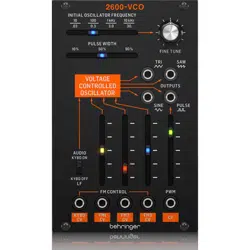
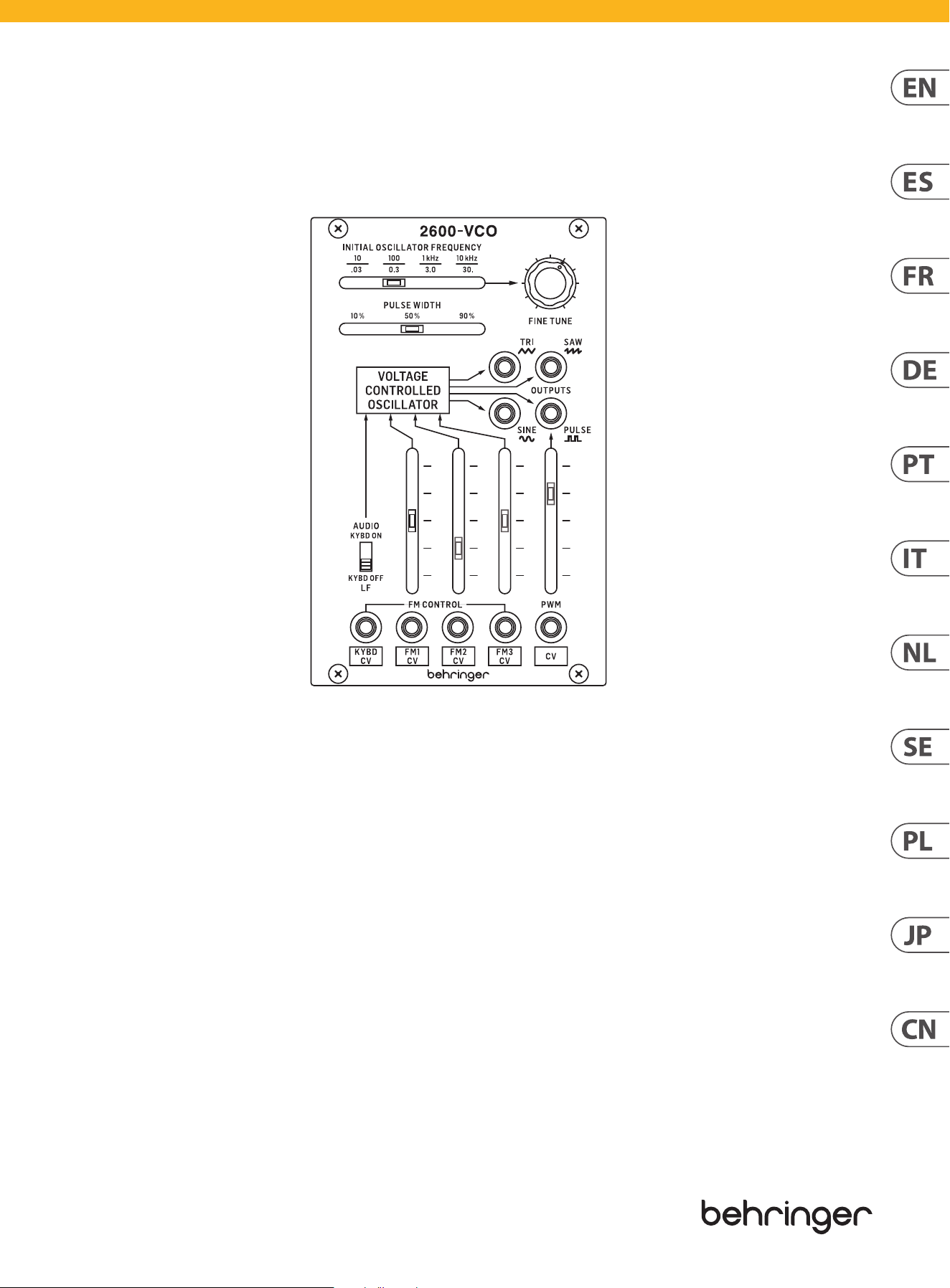
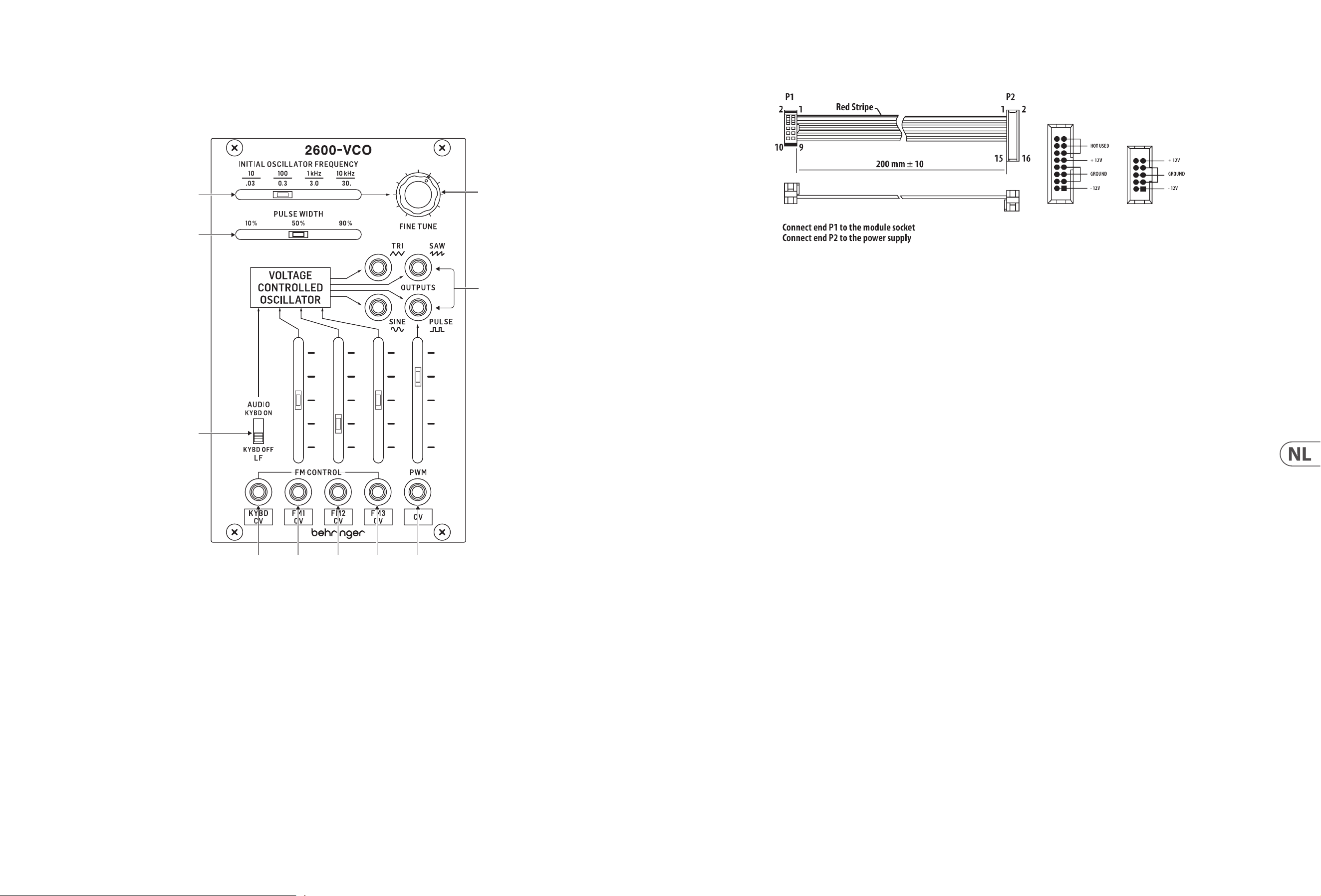
2600-VCO Controls
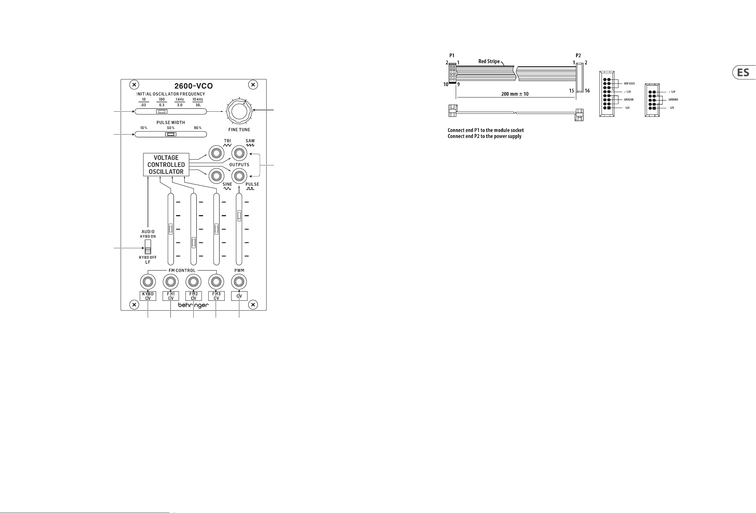
1. INITIAL OSCILLATOR FREQUENCY – selects the initial frequency of the VCO.
In Audio mode the range is 10 Hz to 10 kHz; in Low Frequency mode (LF) the
range is 0.03 Hz to 30 Hz.
2. FINE TUNE – allows the 2600-VCO to be tuned to other VCOs or instruments,
the control has a range of ±0.4 octaves.
3. PULSE WIDTH – allows manual control over the width of the pulse
waveform and has a range from 10% to 90%.
4. OUTPUTS – separate outputs for sine, triangle, sawtooth and pulse
waveforms. All are available simultaneously.
5. KEYBOARD CV INPUT – accepts control voltages from a keyboard or MIDI/
CV converter in the range 0 V – 10 V.
6, 7, 8 FM INPUTS AND LEVELS – input for frequency modulation of the VCO
plus attenuators to control the level of modulation.
9. PULSE WIDTH MODULATION INPUT AND LEVEL – input for an external
source of modulation of the width of the pulse waveform plus attenuator to
control the level of modulation.
10. KEYBOARD ON/OFF SWITCH – allows the keyboard voltage to be switched
off which puts the VCO into Low Frequency mode.
(EN)
Controls
(1)
(3)
(10)
(2)
(4)
(6)(5) (7) (8) (9)
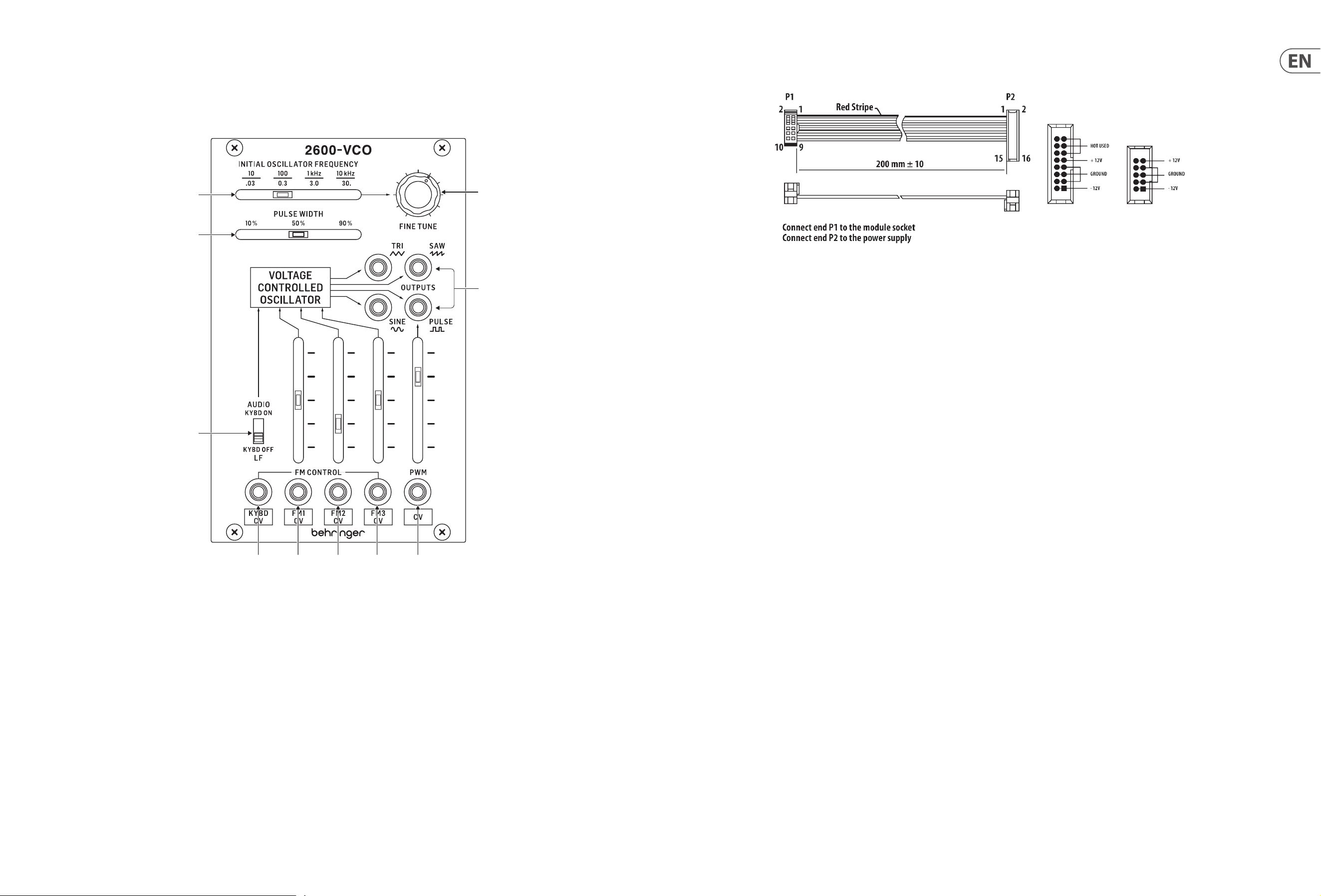
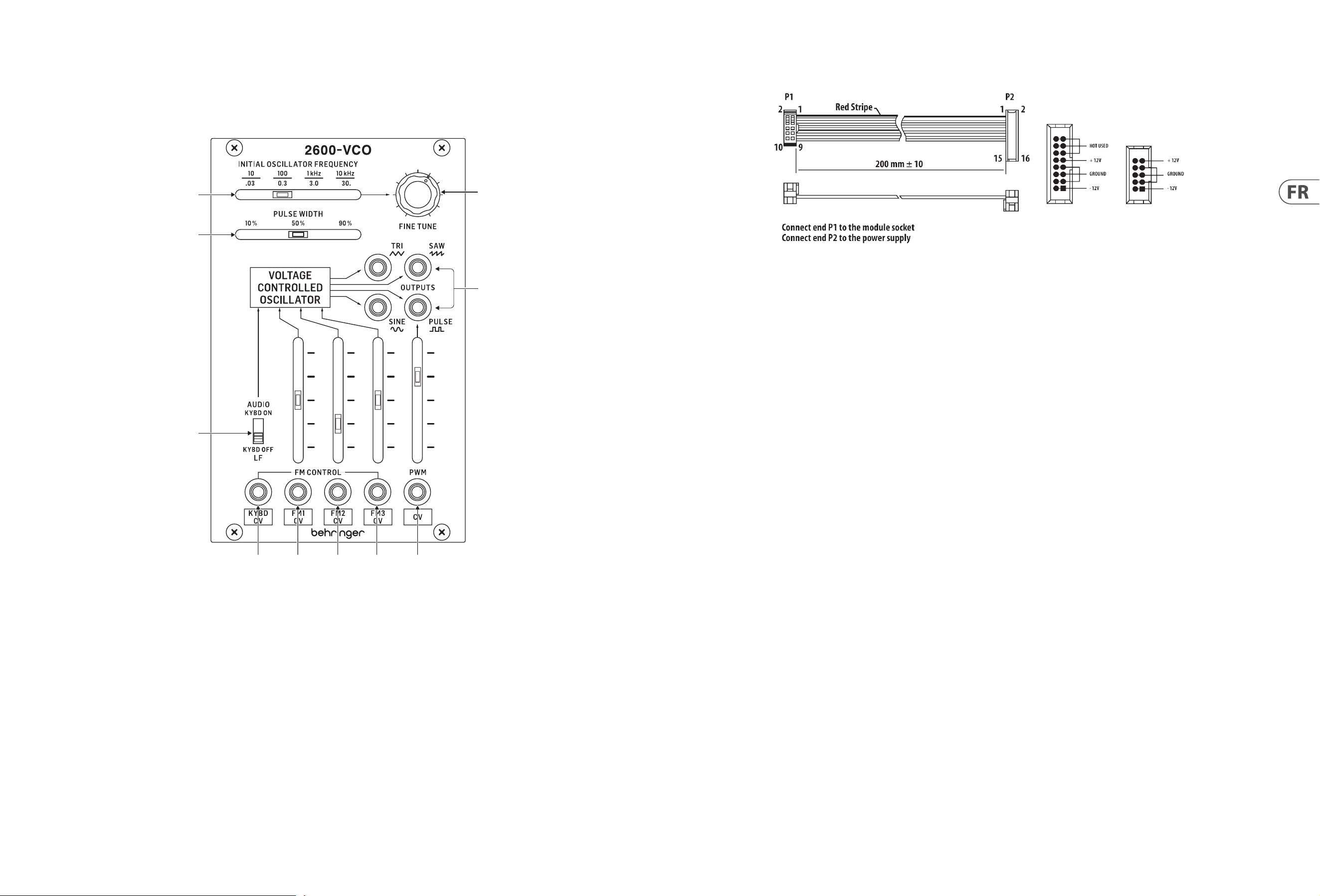
Power Connection
The 2600-VCO module comes with the required power cable for connecting to a
standard Eurorack power supply system. Follow these steps to connect power to
the module. It is easier to make these connections before the module has been
mounted into a rack case.
1. Turn the power supply or rack case power off and disconnect the power cable.
2. Insert the 16-pin connector on the power cable into the socket on the power
supply or rack case. The connector has a tab that will align with the gap in the
socket, so it cannot be inserted incorrectly. If the power supply does not have
a keyed socket, be sure to orient pin 1 (-12 V) with the red stripe on the cable.
3. Insert the 10-pin connector into the socket on the back of the module.
The connector has a tab that will align with the socket for correct orientation.
4. After both ends of the power cable have been securely attached, you may
mount the module in a case and turn on the power supply.
Installation
The necessary screws are included with the module for mounting in a
Eurorack case. Connect the power cable before mounting.
Depending on the rack case, there may be a series of fixed holes spaced 2 HP
apart along the length of the case, or a track that allows individual threaded
plates to slide along the length of the case. The free-moving threaded plates
allow precise positioning of the module, but each plate should be positioned in
the approximate relation to the mounting holes in your module before attaching
the screws.
Hold the module against the Eurorack rails so that each of the mounting holes
are aligned with a threaded rail or threaded plate. Attach the screws part way
to start, which will allow small adjustments to the positioning while you get
them all aligned. After the final position has been established, tighten the
screws down.
8 2600-VCO Quick Start Guide 9
2600-VCO Controles
1. INITIAL OSCILLATOR FREQUENCY – esto le permite elegir la frecuencia inicial
del VCO. En el modo audio el rango es de 10 Hz a 10 KHz; en el modo de baja
frecuencia (LF) el rango será de 0.03 Hz a 30 Hz.
2. FINE TUNE – este control permite afinar el 2600-VCO a otros VCOs o
instrumentos; el control tiene un rango de ±0.4 octavas.
3. PULSE WIDTH – permite el control manual de la amplitud de la forma de
onda de pulso y tiene un rango de 10% a 90%.
4. OUTPUTS – salidas independientes para las formas de onda sinusoidal,
triangular, diente de sierra y pulso. Todas ellas están disponibles de forma
simultánea.
5. KEYBOARD CV INPUT – esta entrada acepta voltajes de control de teclado o
de un convertidor MIDI/CV en un rango de 0 V – 10 V.
6, 7, 8 FM INPUTS AND LEVELS – entradas para la modulación de frecuencia del
VCO más atenuadores para controlar el nivel de la modulación.
9. PULSE WIDTH MODULATION INPUT AND LEVEL – entrada para una fuente
externa de modulación de la amplitud de la forma de onda de pulso más
atenuador para controlar el nivel de la modulación.
10. KEYBOARD ON/OFF SWITCH – permite que el voltaje del teclado sea
desactivado, lo que hará que el VCO quede en el modo de baja frecuencia.
(ES)
Controles
(1)
(3)
(10)
(2)
(4)
(6)(5) (7) (8) (9)
Conexión Eléctrica
El 2600-VCO viene con el cable de alimentación necesario para conectarse a
un sistema de suministro de energía Eurorack estándar. Siga estos pasos para
conectar la energía al módulo. Es más fácil realizar estas conexiones antes de que
el módulo haya sido montado en un estuche de rack.
1. Apague la fuente de alimentación o el suministro de energía del estuche y
desconecte el cable de alimentación.
2. Inserte el conector de 16 pines del cable de alimentación en la toma de
corriente de la fuente de alimentación o del estuche de rack. El conector tiene
una pestaña que se alineará con la separación en la toma, por lo que no se
puede insertar incorrectamente. Si la fuente de alimentación no tiene una
toma con llave, asegúrese de orientar el pin 1 (-12 V) con la raya roja del cable.
3. Inserte el conector de 10 pines en la toma de corriente en la parte posterior
del módulo. El conector tiene una pestaña que se alineará con la toma para
una orientación correcta.
4. Después de que ambos extremos del cable de alimentación hayan sido
asegurados correctamente, puede montar el módulo en un estuche y
encender la fuente de alimentación.
Instalación
Los tornillos necesarios están incluidos con el módulo para montarlo en un
estuche Eurorack. Conecte el cable de alimentación antes de montarlo.
Dependiendo del estuche de rack, puede haber una serie de agujeros fijos
espaciados a 2 HP a lo largo del estuche, o una pista que permite que las placas
roscadas individuales se deslicen a lo largo del estuche. Las placas roscadas de
movimiento libre permiten una posición precisa del módulo, pero cada placa
debe posicionarse en relación aproximada con los agujeros de montaje en su
módulo antes de sujetar los tornillos.
Sostenga el módulo contra los rieles Eurorack para que cada uno de los agujeros
de montaje estén alineados con un riel roscado o una placa roscada. Sujete los
tornillos parcialmente para empezar, lo que permitirá pequeños ajustes en
la posición mientras los alinea todos. Después de que se haya establecido la
posición final, apriete los tornillos.
10 2600-VCO Quick Start Guide 11
2600-VCO Réglages
1. INITIAL OSCILLATOR FREQUENCY – permet de sélectionner la fréquence
initiale du VCO. En mode Audio, la fréquence peut varier entre 10 Hz et
10 KHz ; en mode LF, la fréquence peut varier entre 0,3 Hz et 30 Hz.
2. FINE TUNE – permet d’accorder le VCO du 2600 par rapport à d’autres VCO
ou instruments; la plage de réglage est de ±0.4 octave.
3. PULSE WIDTH – permet de régler manuellement la largeur de l’onde pulse
(de 10% à 90%).
4. OUTPUTS – sorties séparées pour les ondes sinusoïdale, triangulaire, en dent
de scie et pulse. Toutes sont disponibles simultanément.
5. KEYBOARD CV INPUT – peut recevoir une tension de contrôle de 0 V à 10 V
transmise par un clavier ou un convertisseur MIDI/CV.
6, 7, 8 FM INPUTS AND LEVELS – entrées pour la modulation de la fréquence du
VCO et atténuateurs du niveau de modulation.
9. PULSE WIDTH MODULATION INPUT AND LEVEL – entrée pour une source
externe de modulation de la largeur de l’onde pulse et atténuateur du
niveau de modulation.
10. KEYBOARD ON/OFF SWITCH – permet de désactiver la tension du clavier et
de placer le VCO en mode LF.
(FR)
Réglages
(1)
(3)
(10)
(2)
(4)
(6)(5) (7) (8) (9)
Connexion Électrique
Le 2600-VCO module est livré avec le câble d’alimentation requis pour la
connexion à un système d’alimentation standard Eurorack. Suivez ces étapes
pour connecter l’alimentation au module. Il est plus facile d’effectuer ces
connexions avant que le module n’ait été monté dans un boîtier de rack.
1. Mettez le bloc d’alimentation ou le boîtier de rack hors tension et
débranchez le câble d’alimentation.
2. Insérez le connecteur à 16 broches du câble d’alimentation dans la prise du
bloc d’alimentation ou du boîtier du rack. Le connecteur a une languette qui
s’alignera avec l’espace dans la prise, de sorte qu’il ne peut pas être inséré de
manière incorrecte. Si le bloc d’alimentation n’a pas de prise à clé, veillez à
orienter la broche 1 (-12 V) avec la bande rouge sur le câble.
3. Insérez le connecteur à 10 broches dans la prise à l’arrière du module.
Le connecteur a une languette qui s’alignera avec la prise pour une
orientation correcte.
4. Une fois que les deux extrémités du câble d’alimentation ont été
solidement fixées, vous pouvez monter le module dans un boîtier et allumer
l’alimentation.
Installation
Les vis nécessaires sont incluses avec le module pour le montage dans un boîtier
Eurorack. Connectez le câble d’alimentation avant le montage.
Selon le cas de rack, il peut y avoir une série de trous fixes espacés de 2 HP sur
la longueur du cas, ou une piste qui permet aux plaques filetées individuelles
de glisser le long de la longueur du cas. Les plaques filetées à déplacement libre
permettent un positionnement précis du module, mais chaque plaque doit être
positionnée approximativement par rapport aux trous de montage de votre
module avant de fixer les vis.
Maintenez le module contre les rails Eurorack de sorte que chacun des trous
de montage soit aligné avec un rail fileté ou une plaque filetée. Fixez les vis
partiellement pour commencer, ce qui permettra de petits ajustements au
positionnement pendant que vous les alignerez tous. Une fois la position finale
établie, serrez les vis vers le bas.
12 2600-VCO Quick Start Guide 13
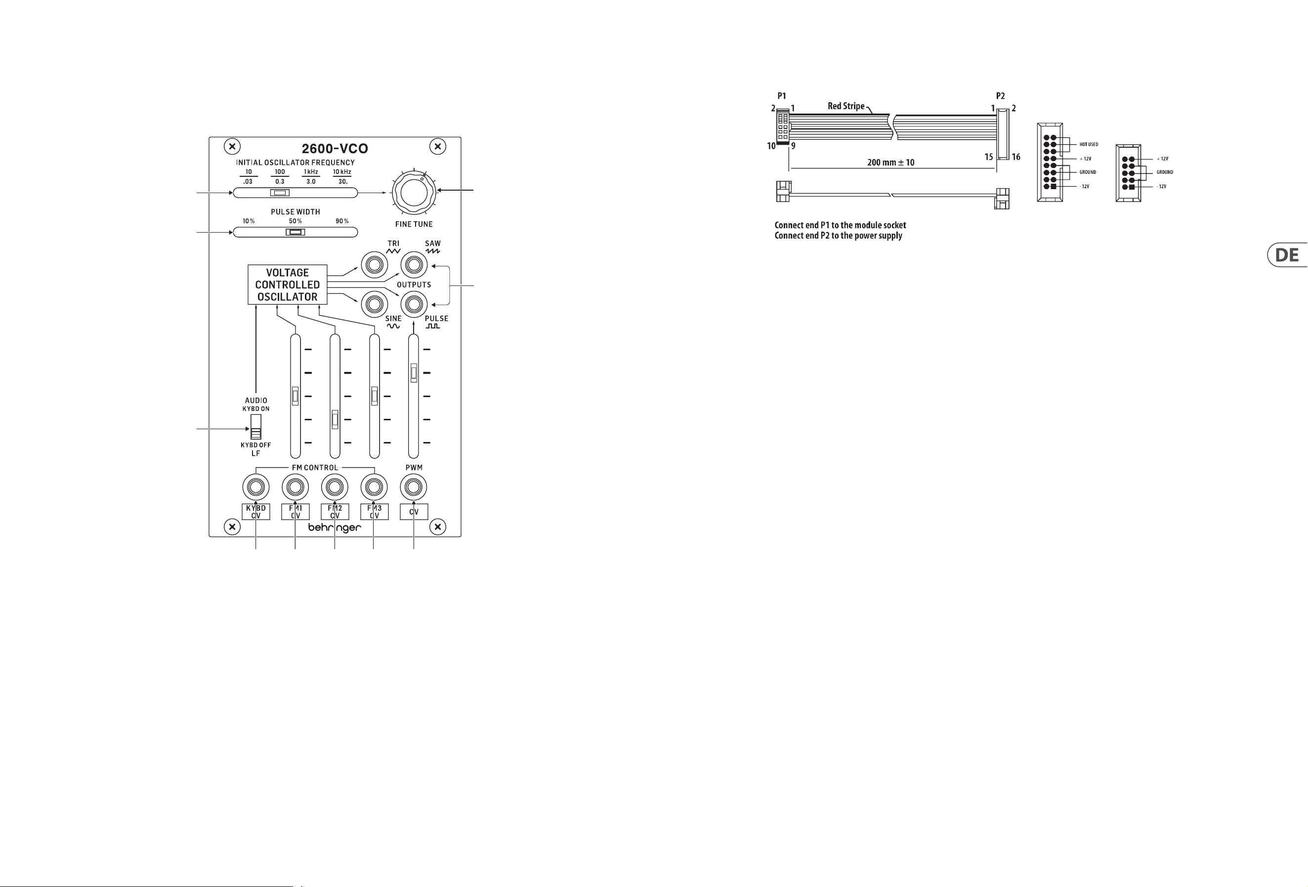
Das Modul 2600-VCO wird mit dem erforderlichen Stromkabel geliefert, um es
mit einem Standard-Eurorack-Netzteil zu verbinden. Befolgen Sie diese Schritte,
um das Modul mit Strom zu versorgen. Es ist einfacher, diese Verbindungen
herzustellen, bevor das Modul in ein Rackgehäuse montiert wurde.
1. Schalten Sie das Netzteil oder die Stromversorgung des Rackgehäuses aus
und ziehen Sie das Stromkabel ab.
2. Stecken Sie den 16-poligen Stecker des Stromkabels in die Buchse des
Netzteil oder des Rackgehäuses. Der Stecker hat eine Lasche, die sich
mit der Lücke in der Buchse ausrichtet, sodass er nicht falsch eingeführt
werden kann. Wenn das Netzteil keine gekennzeichnete Buchse hat,
stellen Sie sicher, dass Sie den Pin 1 (-12 V) mit dem roten Streifen auf dem
Kabel ausrichten.
3. Stecken Sie den 10-poligen Stecker in die Buchse auf der Rückseite des
Moduls. Der Stecker hat eine Lasche, die sich mit der Buchse zur korrekten
Ausrichtung ausrichtet.
4. Nachdem beide Enden des Stromkabels sicher befestigt wurden,
können Sie das Modul in einem Gehäuse montieren und die
Stromversorgung einschalten.
Installation
Die benötigten Schrauben sind im Modul enthalten, um es in ein Eurorack-
Gehäuse zu montieren. Schließen Sie das Stromkabel vor der Montage an.
Je nach Rackgehäuse kann es entweder eine Reihe von festen Löchern geben,
die entlang der Länge des Gehäuses im Abstand von 2 HP angeordnet sind, oder
eine Schiene, die es einzelnen Gewindeplatten ermöglicht, entlang der Länge
des Gehäuses zu gleiten. Die frei beweglichen Gewindeplatten ermöglichen
eine präzise Positionierung des Moduls, aber jede Platte sollte in etwa in Bezug
auf die Montagelöcher in Ihrem Modul positioniert werden, bevor Sie die
Schrauben anbringen.
Halten Sie das Modul gegen die Eurorack-Schienen, sodass jedes der
Montagelöcher mit einer Gewindeschraube oder einer Gewindeplatte
ausgerichtet ist. Beginnen Sie damit, die Schrauben teilweise anzuziehen,
was kleine Anpassungen der Position ermöglicht, während Sie sie alle
ausrichten. Nachdem die endgültige Position festgelegt wurde, ziehen Sie die
Schrauben fest.
Netzanschluss2600-VCO Bedienelemente
1. INITIAL OSCILLATOR FREQUENCY – wählt die anfängliche Frequenz
des VCOs. Im Audiomodus beträgt der Bereich 10 Hz bis 10 kHz. Im Low
Frequency-Modus (LF) beträgt der Bereich 0.03 Hz bis 30 Hz.
2. FINE TUNE – Zum Abstimmen des 2600-VCOs auf andere VCOs oder
Instrumente. Der Regler hat einen Bereich von ±0.4 Oktaven.
3. PULSE WIDTH – ermöglicht die manuelle Kontrolle über die Breite der
Pulswellenform über einen Bereich von 10 % bis 90 %.
4. OUTPUTS – separate Ausgänge für Sinus-, Dreieck-, Sägezahn- und
Pulswellenformen. Alle sind gleichzeitig verfügbar.
5. KEYBOARD CV INPUT – akzeptiert Steuerspannungen von Tastaturen oder
MIDI/CV-Wandlern im Bereich 0 V - 10 V.
6, 7, 8 FM INPUTS AND LEVELS – Eingang für die Frequenzmodulation des
VCOs sowie Dämpfungsglied zur Steuerung des Modulationspegels.
9. PULSE WIDTH MODULATION INPUT AND LEVEL - Eingang für eine externe
Quelle zum Modulieren der Pulswellenbreite sowie Dämpfungsglied zur
Steuerung des Modulationspegels.
10. KEYBOARD ON/OFF SWITCH – ermöglicht das Ausschalten der
Tastaturspannung, wodurch der VCO in den Low Frequency-Modus
geschaltet wird.
(DE)
Bedienelemente
(1)
(3)
(10)
(2)
(4)
(6)(5) (7) (8) (9)
14 2600-VCO Quick Start Guide 15
2600-VCO Controles
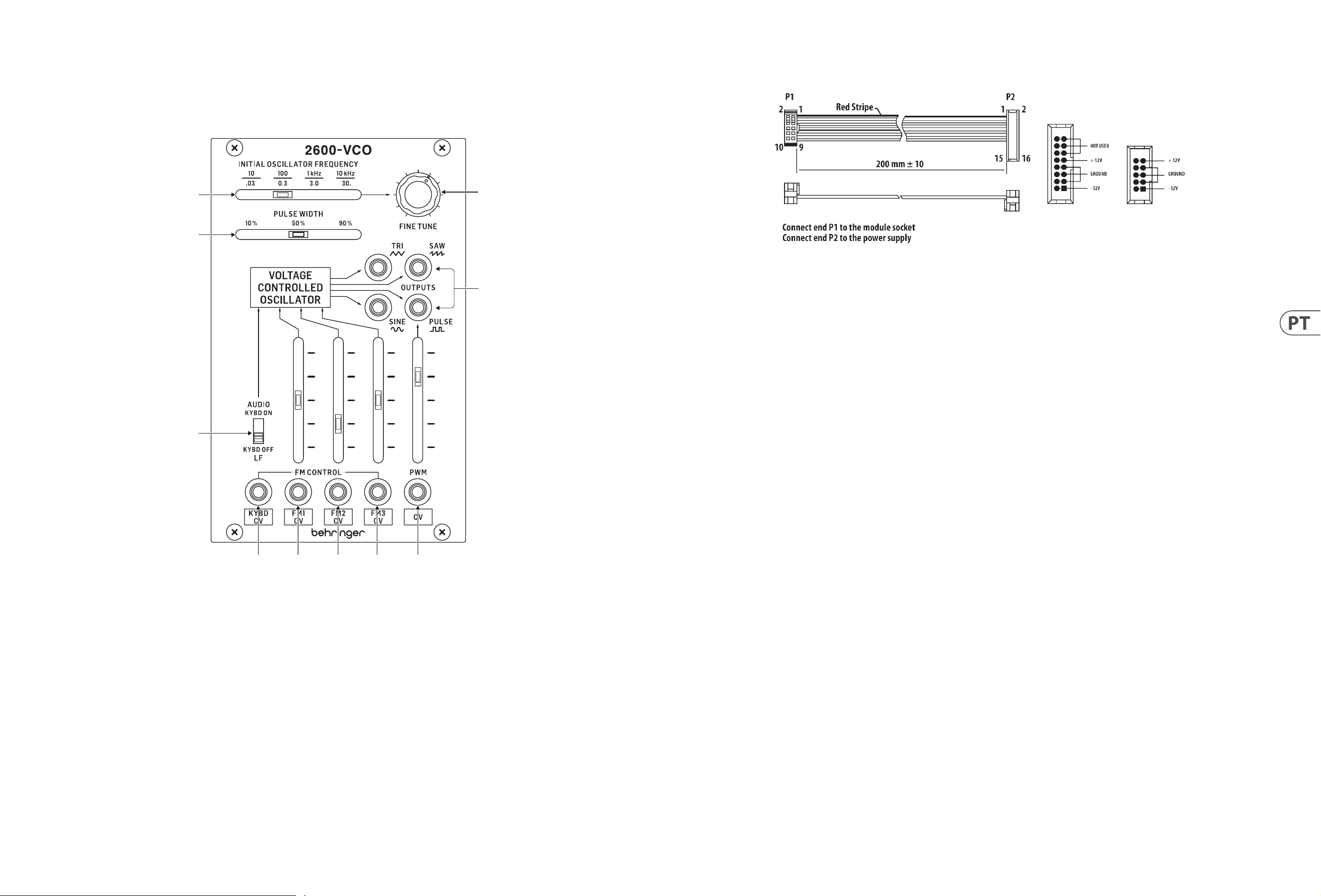
1. INITIAL OSCILLATOR FREQUENCY – seleciona a frequência inicial do VCO.
No modo ’audio’, o alcance é de 10 Hz a 10 KHz; no modo de baixa frequência
(LF) o alcance é de 0.03 Hz a 30 Hz.
2. FINE TUNE – permite que o 2600-VCO seja sintonizado a outros VCOs ou
instrumentos, o controle tem um alcance de ±0.4 oitavas.
3. PULSE WIDTH – possibilita controle manual da amplitude da forma de onda
pulso com alcance entre 10% e 90%.
4. OUTPUTS – separa saídas de formas de onda senoidais, triangulares, dente
de serra e pulso. Todas disponíveis simultaneamente.
5. KEYBOARD CV INPUT – aceita tensão de controle proveniente de um
teclado ou conversor MIDI/CV em uma gama de 0 V – 10 V.
6, 7, 8 FM INPUTS AND LEVELS – entrada para a modulação de frequência do
VCO além de atenuadores para o controle do nível de modulação.
9. PULSE WIDTH MODULATION INPUT AND LEVEL – entrada para fonte de
modulação externa da amplitude da forma de onda pulso além do atenuador
de controle do nível de modulação.
10. KEYBOARD ON/OFF SWITCH – possibilita que a tensão do teclado seja
desligada, o que coloca o VCO no modo de baixa frequência.
(PT)
Controles
(1)
(3)
(10)
(2)
(4)
(6)(5) (7) (8) (9)
O módulo 2600-VCO vem com o cabo de alimentação necessário para conectar-se
a um sistema de alimentação padrão Eurorack. Siga estes passos para conectar
energia ao módulo. É mais fácil fazer essas conexões antes que o módulo seja
montado em um estojo de rack.
1. Desligue a fonte de alimentação ou o fornecimento de energia do rack e
desconecte o cabo de alimentação.
2. Insira o conector de 16 pinos do cabo de alimentação na tomada da fonte
de alimentação ou do rack. O conector tem uma aba que se alinhará com
o espaço na tomada, para que não possa ser inserido incorretamente.
Se a fonte de alimentação não tiver uma tomada com chave, certifique-se de
orientar o pino 1 (-12 V) com a faixa vermelha no cabo.
3. Insira o conector de 10 pinos na tomada na parte traseira do módulo.
O conector tem uma aba que se alinhará com a tomada para a
orientação correta.
4. Depois que ambas as extremidades do cabo de alimentação estiverem
firmemente conectadas, você pode montar o módulo em um estojo e ligar a
fonte de alimentação.
Instalação
Os parafusos necessários estão incluídos com o módulo para montagem em um
estojo Eurorack. Conecte o cabo de alimentação antes de montar.
Dependendo do estojo de rack, pode haver uma série de furos fixos espaçados
2 HP de distância ao longo do comprimento do estojo, ou uma trilha que permite
que placas rosqueadas individuais deslizem ao longo do comprimento do estojo.
As placas rosqueadas de movimento livre permitem um posicionamento preciso
do módulo, mas cada placa deve ser posicionada em relação aproximada aos
furos de montagem em seu módulo antes de fixar os parafusos.
Segure o módulo contra os trilhos Eurorack para que cada um dos furos
de montagem esteja alinhado com um trilho ou placa rosqueada. Fixe os
parafusos parcialmente para começar, o que permitirá pequenos ajustes na
posição enquanto você os alinha. Depois que a posição final for estabelecida,
aperte os parafusos.
Conexão de Força

16 2600-VCO Quick Start Guide 17
2600-VCO Controlli
1. INITIAL OSCILLATOR FREQUENCY – seleziona la frequenza iniziale del VCO.
Nel modo audio la gamma va da 10 Hz a 10 KHz; nel modo Low Frequency (LF) la
gamma è da 0.03 Hz a 30 Hz.
2. FINE TUNE – permette di accordare il 2600-VCO con altri VCO o strumenti, il
controllo ha una gamma di ±0.4 di ottava.
3. PULSE WIDTH – consente il controllo manuale della larghezza della forma
d’onda impulsiva e ha un intervallo dal 10% al 90%.
4. OUTPUTS – uscite separate per forma d’onda sinusoidale, triangolare, a
dente di sega e impulsiva. Sono tutte disponibili contemporaneamente.
5. KEYBOARD CV INPUT – accetta tensioni di controllo da tastiera o
convertitore MIDI/CV nell’intervallo 0 V – 10 V.
6, 7, 8 FM INPUTS AND LEVELS – ingressi per la modulazione di frequenza del
VCO e attenuatori per il controllo del livello di modulazione.
9. PULSE WIDTH MODULATION INPUT AND LEVEL – ingresso per una sorgente
esterna di modulazione dell’ampiezza della forma d’onda impulsiva e
attenuatore per controllare il livello di modulazione.
10. KEYBOARD ON/OFF SWITCH – permette di escludere la tensione della
tastiera; ciò commuta il VCO nel modo Low Frequency.
(IT)
Controlli
(1)
(3)
(10)
(2)
(4)
(6)(5) (7) (8) (9)
Il modulo 2600-VCO è dotato del cavo di alimentazione necessario per collegarsi
a un sistema di alimentazione standard Eurorack. Seguire questi passaggi per
collegare l’alimentazione al modulo. È più facile fare queste connessioni prima
che il modulo sia montato in un case a rack.
1. Spegnere l’alimentazione o il rack e scollegare il cavo di alimentazione.
2. Inserire il connettore a 16 pin del cavo di alimentazione nella presa
dell’alimentatore o del rack. Il connettore ha una linguetta che si allineerà
con lo spazio nella presa, quindi non può essere inserito in modo scorretto.
Se l’alimentatore non ha una presa a chiave, assicurarsi di orientare il pin 1
(-12 V) con la striscia rossa sul cavo.
3. Inserire il connettore a 10 pin nella presa sul retro del modulo. Il connettore
ha una linguetta che si allineerà con la presa per una corretta orientazione.
4. Dopo che entrambi gli estremi del cavo di alimentazione sono stati
collegati saldamente, è possibile montare il modulo in un case e
accendere l’alimentazione.
Installazione
Le viti necessarie sono incluse con il modulo per il montaggio in un case Eurorack.
Collegare il cavo di alimentazione prima del montaggio.
A seconda del case a rack, potrebbe esserci una serie di fori fissi spaziati a 2 HP
di distanza lungo la lunghezza del case, o una guida che consente alle singole
piastre filettate di scorrere lungo la lunghezza del case. Le piastre filettate mobili
consentono un posizionamento preciso del modulo, ma ogni piastre dovrebbe
essere posizionata in relazione approssimativa ai fori di montaggio nel modulo
prima di fissare le viti.
Tenere il modulo contro le rotaie Eurorack in modo che ciascuno dei fori di
montaggio sia allineato con una rotaia filettata o una piastra filettata. Fissare
le viti in modo parziale per iniziare, ciò consentirà piccoli aggiustamenti alla
posizione mentre si allineano tutti. Dopo che la posizione finale è stata stabilita,
stringere le viti.
Connessione di Alimentazione
18 2600-VCO Quick Start Guide 19
2600-VCO Bediening
1. INITIAL OSCILLATOR FREQUENCY – Selecteert de beginfrequentie van de
VCO. In audiomodus is het bereik 10 Hz tot 10 KHz; in lage frequentiemodus
(LF) bedraagt het bereik 0.03 Hz tot 30 Hz.
2. FINE TUNE – Hiermee kan de 2600-VCO met andere VCO’s of instrumenten
worden gestemd. De regelaar heeft een bereik van ±0.4 octaven.
3. PULSE WIDTH – geeft handmatige controle over de breedte van de
pulsgolfvorm en heeft een bereik van 10% tot 90%.
4. OUTPUTS – aparte uitgangen voor sinus-, driehoek-, zaagtand-, en
pulsgolfvormen. Alle golfvormen zijn tegelijkertijd beschikbaar.
5. KEYBOARD CV INPUT – accepteert stuurspanning vanaf het keyboard of de
MIDI/CV-converter in het bereik 0 V – 10 V.
6, 7, 8 FM INPUTS AND LEVELS – ingangen voor frequentiemodulatie van de
VCO plus attenuators om het modulatieniveau te regelen.
9. PULSE WIDTH MODULATION INPUT AND LEVEL – ingang voor een externe
modulatie van de breedte van de pulsgolfvorm plus attenuator om het
modulatieniveau te regelen.
10. KEYBOARD ON/OFF SWITCH – zorgt ervoor dat de toetsenbordspanning
kan worden uitgeschakeld, waardoor de VCO naar lage frequentiemodus
wordt omgeschakeld.
(NL)
Bediening
(1)
(3)
(10)
(2)
(4)
(6)(5) (7) (8) (9)
Het module 2600-VCO wordt geleverd met de benodigde stroomkabel voor het
aansluiten op een standaard Eurorack-voedingssysteem. Volg deze stappen om
de stroom aan te sluiten op het module. Het is makkelijker om deze verbindingen
te maken voordat het module in een rack case is gemonteerd.
1. Schakel de voeding uit of schakel de stroom van het rack uit en koppel de
stroomkabel los.
2. Steek de 16-pins connector van de stroomkabel in de socket van de voeding
of het rack. De connector heeft een lipje dat zal uitlijnen met de opening in de
socket, zodat het niet verkeerd kan worden ingestoken. Als de voeding geen
sleutelgat heeft, zorg er dan voor dat pin 1 (-12 V) wordt georiënteerd met de
rode streep op de kabel.
3. Steek de 10-pins connector in de socket aan de achterkant van het module.
De connector heeft een lipje dat zal uitlijnen met de socket voor de juiste
oriëntatie.
4. Nadat beide uiteinden van de stroomkabel stevig zijn bevestigd, kunt u het
module in een case monteren en de voeding inschakelen.
Installatie
De benodigde schroeven zijn inbegrepen bij het module voor montage in een
Eurorack-case. Sluit de stroomkabel aan voordat u gaat monteren.
Afhankelijk van het rackcase, kunnen er een reeks vaste gaten zijn die 2 HP uit
elkaar staan langs de lengte van de case, of een rail die individuele schroefplaten
langs de lengte van de case laat glijden. De vrij bewegende schroefplaten zorgen
voor een nauwkeurige positionering van het module, maar elke plaat moet
worden gepositioneerd in de benaderende relatie tot de montagelocaties in uw
module voordat u de schroeven bevestigt.
Houd het module tegen de Eurorack-rails zodat elk van de montagelocaties is
uitgelijnd met een schroefrail of schroefplaat. Bevestig de schroeven gedeeltelijk
om te beginnen, wat kleine aanpassingen aan de positionering mogelijk maakt
terwijl u ze allemaal uitlijnt. Nadat de definitieve positie is vastgesteld, draait u
de schroeven vast.
Stroomaansluiting
20 2600-VCO Quick Start Guide 21
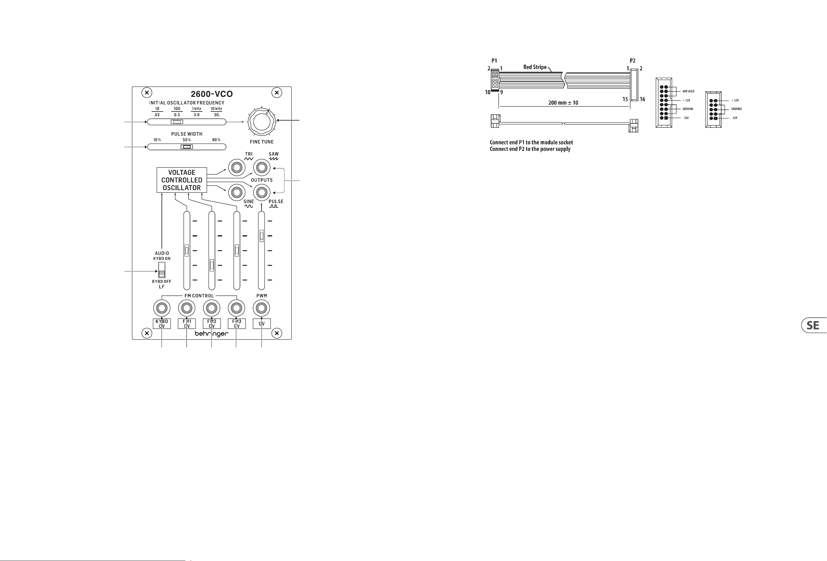
2600-VCO Kontroller
1. INITIAL OSCILLATOR FREQUENCY – väljer den initiala frekvensen för
VCO:n. I ljudläge är intervallet 10 Hz till 10 kHz, i lågfrekvensläge (LF)
är intervallet 0,03 Hz till 30 Hz.
2. FINE TUNE – gör att 2600-VCO kan stämmas efter andra VCO:er eller
instrument, kontrollen har ett omfång på ±0.4 oktaver.
3. PULSE WIDTH – möjliggör manuell styrning av pulsvågformens bredd och
har ett omfång från 10 % till 90 %.
4. OUTPUTS – separata utgångar för sinus-, triangel-, sågtand- och
pulsvågformer. Alla är tillgängliga samtidigt.
5. KEYBOARD CV INPUT – tar emot styrspänningar från klaviatur eller MIDI/
CV-omvandlare i intervallet 0 V–10 V.
6, 7, 8 FM INPUTS AND LEVELS – ingång för frekvensmodulering av VCO:n plus
dämpare för att styra modulationsnivån.
9. PULSE WIDTH MODULATION INPUT AND LEVEL – ingång för en extern
källa för modulation av pulsvågformens bredd plus dämpare för att styra
modulationsnivån.
10. KEYBOARD ON/OFF SWITCH – gör att klaviaturens spänning kan stängas
av, vilket ställer in VCO: n på lågfrekvensläge.
(SE)
Kontroller
(1)
(3)
(10)
(2)
(4)
(6)(5) (7) (8) (9)
Strömanslutning
2600-VCO-modulen levereras med den nödvändiga strömkabeln för anslutning
till ett vanligt Eurorack-nätaggregat. Följ dessa steg för att ansluta ström
till modulen. Det är lättare att göra dessa anslutningar innan modulen har
monterats i ett rackfodral.
1. Stäng av strömmen eller rackhöljet och koppla bort strömkabeln.
2. Sätt i den 16-poliga kontakten på strömkabeln i uttaget på nätaggregatet
eller rackfodralet. Kontaktdonet har en flik som kommer i linje med springan
i uttaget så att den inte kan sättas in felaktigt. Om strömförsörjningen inte
har ett nyckeluttag, se till att orientera stift 1 (-12 V) med den röda remsan
på kabeln.
3. Sätt i 10-polig kontakt i uttaget på baksidan av modulen. Kontaktdonet har
en flik som kommer i linje med uttaget för korrekt orientering.
4. När båda ändarna av strömkabeln har anslutits ordentligt kan du montera
modulen i ett fodral och slå på strömförsörjningen.
Installation
De nödvändiga skruvarna ingår i modulen för montering i ett Eurorack-fodral.
Anslut strömkabeln före montering.
Beroende på stativhöljet kan det finnas en serie fasta hål som är åtskilda 2
hk längs höljets längd eller ett spår som gör att enskilda gängade plattor kan
glida längs höljets längd. De fritt rörliga gängade plattorna möjliggör exakt
positionering av modulen, men varje platta bör placeras i ungefärlig relation till
monteringshålen i din modul innan skruvarna fästs.
Håll modulen mot Eurorack-skenorna så att var och en av monteringshålen ligger
i linje med en gängad skena eller gängad platta. Fäst skruvarna delvis för att
börja, vilket gör det möjligt att justera små positioner medan du justerar dem
alla. När den slutliga positionen har fastställts drar du åt skruvarna.

22 2600-VCO Quick Start Guide 23
2600-VCO Sterowanica
1. INITIAL OSCILLATOR FREQUENCY – wybiera pierwotną częstotliwość
VCO. W trybie audio przedział wynosi od 10 Hz do 10KHz; w trybie niskich
częstotliwości (LF) przedział wynosi od 0.03 Hz do 30 Hz.
2. FINE TUNE – pozwala 2600-VCO na dostrojenie do innych VCO lub
instrumentów. Ta regulacja ma przedział ±0.4 oktawy.
3. PULSE WIDTH – pozwala na ręczną kontrolę nad szerokością kształtu fali
pulsu. Ta regulacja ma przedział od 10% do 90%.
4. OUTPUTS – osobne wyjścia dla fal sinusoidalnych, trójkątnych,
piłokształtnych oraz pulsu. Wszystkie są dostępne jednocześnie.
5. KEYBOARD CV INPUT – przyjmuje napięcia kontrolne z klawiatury lub
konwertera MIDI/CV w przedziale 0 V – 10 V.
6, 7, 8 FM INPUTS AND LEVELS – wejście dla modulacji częstotliwości VCO oraz
tłumiki pozwalające na kontrolowanie poziomu modulacji.
9. PULSE WIDTH MODULATION INPUT AND LEVEL – wejście dla zewnętrznego
źródła modulacji szerokości kształtu fali pulsu oraz tłumik pozwalający na
kontrolę poziomu modulacji.
10. KEYBOARD ON/OFF SWITCH – pozwala na wyłączenie napięcia klawiatury,
co przełącza VCO na tryb niskich częstotliwości.
(PL)
Sterowanica
(1)
(3)
(10)
(2)
(4)
(6)(5) (7) (8) (9)
Podłączenie Zasilania
Moduł 2600-VCO jest dostarczany z wymaganym kablem zasilającym do
podłączenia do standardowego systemu zasilania Eurorack. Wykonaj poniższe
czynności, aby podłączyć zasilanie do modułu. Łatwiej jest wykonać te
połączenia przed zamontowaniem modułu w obudowie rack.
1. Wyłącz zasilacz lub obudowę szafy i odłącz kabel zasilający.
2. Włóż 16-stykowe złącze przewodu zasilającego do gniazda w zasilaczu lub w
szafie typu Rack. Złącze ma wypustkę, która będzie wyrównana ze szczeliną
w gnieździe, więc nie można jej nieprawidłowo włożyć. Jeśli zasilacz nie
ma gniazda z kluczem, należy zorientować styk 1 (-12 V) z czerwonym
paskiem na kablu.
3. Włóż 10-pinowe złącze do gniazda z tyłu modułu. Złącze ma wypustkę,
która będzie wyrównana z gniazdem, aby zapewnić prawidłową orientację.
4. Po solidnym zamocowaniu obu końców kabla zasilającego można
zamontować moduł w obudowie i włączyć zasilacz.
Instalacja
Do modułu dołączone są niezbędne śruby do montażu w skrzynce Eurorack.
Podłącz kabel zasilający przed montażem.
W zależności od obudowy szafy może występować szereg stałych otworów
rozmieszczonych w odstępach 2 HP na całej długości obudowy lub prowadnica,
która umożliwia przesuwanie pojedynczych gwintowanych płyt wzdłuż całej
obudowy. Swobodnie poruszające się gwintowane płytki umożliwiają precyzyjne
ustawienie modułu, ale każda płyta powinna być ustawiona w przybliżeniu w
stosunku do otworów montażowych w module przed przykręceniem śrub.
Przytrzymaj moduł na szynach Eurorack, tak aby każdy z otworów montażowych
był wyrównany z szyną gwintowaną lub płytą gwintowaną. Wkręć śruby
częściowo, aby rozpocząć, co pozwoli na drobne korekty położenia, gdy wszystkie
zostaną wyrównane. Po ustaleniu ostatecznego położenia dokręcić śruby.
24 2600-VCO Quick Start Guide 25
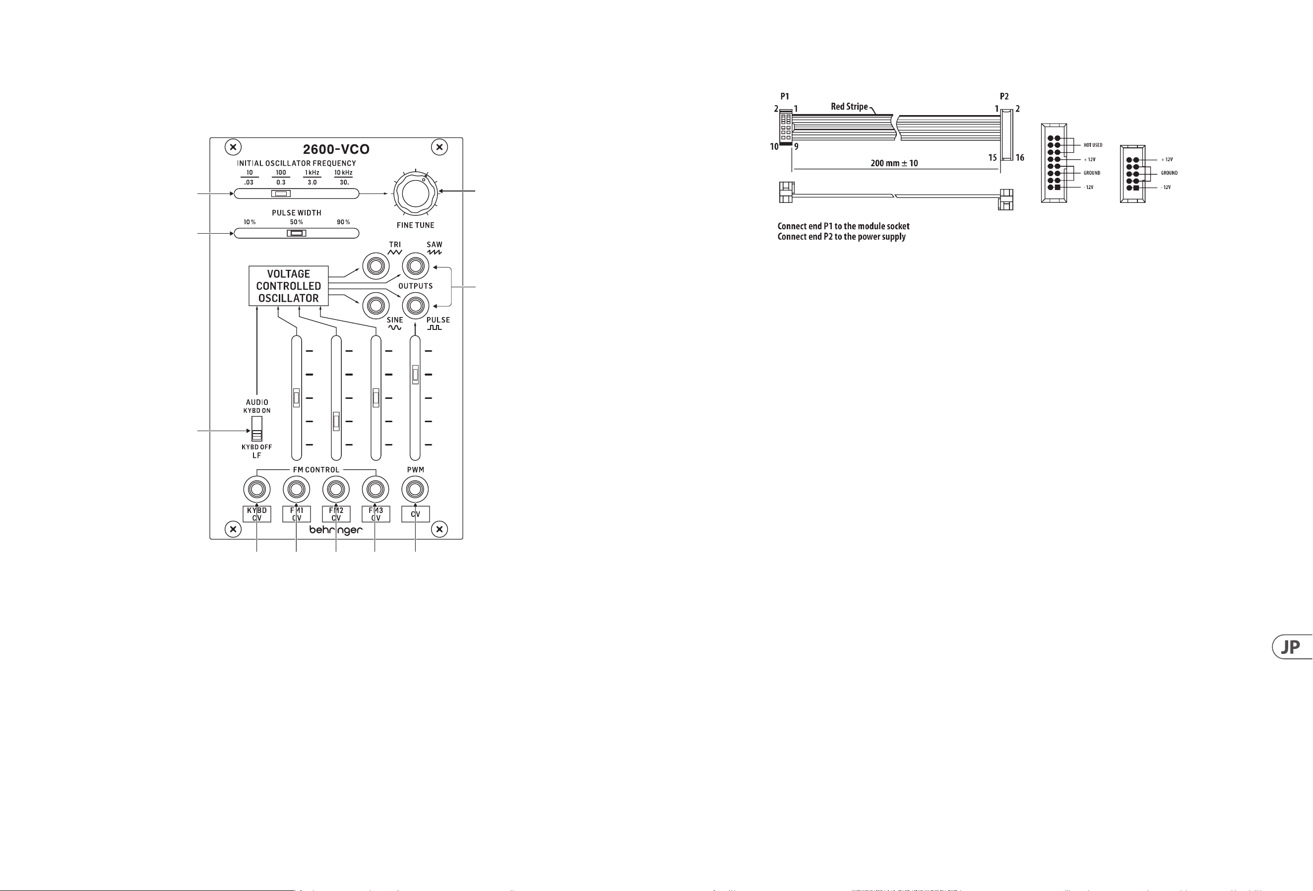
2600-VCO コントロール
1. INITIAL OSCILLATOR FREQUENCY – VCO の初期周波数を選択します。
オーディオモードでは 範 囲は 10 Hz ~ 10 KHz です; 低周波モー
ド (LF) では範囲は 0.03 Hz ~ 30 Hz となります。
2. FINE TUNE – 2600-VCO を別の VCO またはインストゥルメントに合
わせて、調節範囲 ± 0.4 オクターブでチューニングできます。
3. PULSE WIDTH – パルス波の幅を手動で、 10% ~ 90% の間で制
御します。
4. OUTPUTS – サイン波、三角波、ノコギリ波、およびパルス波の
各 出 力で す。すべて 同 時 使 用 が 可 能 です。
5. KEYBOARD CV INPUT – キーボードまたは MID/ CV コンバーターか
ら 0 V – 10 V の 範 囲 のコントロールボ ルテ ージ を 受け入れます。
6, 7, 8 FM INPUTS AND LEVELS – VCO の周波 数モジュレーションへの
入力および、 モジュレーションのレベルを制御するアッテネ
ーター。
9. PULSE WIDTH MODULATION INPUT AND LEVEL – パルス波幅の外部
モジュレーションソース入 力および、モジュレーションのレベ
ルを制御するアッテネーター。
10. KEYBOARD ON/OFF SWITCH –
キーボードボルテージをオフに切り替え、VCO を低周波モード
にします。
(JP)
コントロール
(1)
(3)
(10)
(2)
(4)
(6)(5) (7) (8) (9)
電源接続
2600-VCO モジュールには、標準の Eurorack 電 源システムに接 続する
ため の 必 要 な 電 源ケーブルが 付属していま す。モジュールに電 源 を
接続するには、以下の手順に従ってください。モジュールがラック
ケースに取り付けられる前にこれらの接続を行う方が簡単です。
1. 電源を切り、ラックケースの電源を切り、電源ケーブルを取り
外してください 。
2. 電 源 ケーブル の 16 ピンコネクタを電 源供給装置またはラッ
クケースのソケットに挿入します。コネクタには、ギャップに
合わせるタブが付いているため、誤って挿入することはありま
せん。電源供給装置にキー付きソケットがない場合は、ケー
ブル の 赤 いストライプとピン 1 (-12 V) を整列させてください。
3. モジュールの背面のソケットに 10 ピンコネクタを挿入します。
コネクタには、正しい向きに整列するタブが付いています。
4. 両端の電源ケーブルがしっかりと取り付けられた後、モジュー
ルをケースに取り付けて、 電源をオンにしてください。
インストール
Eurorack ケースに取り付けるための必要なネジがモジュールに付属
しています。取り付 ける前に電 源 ケーブル を接 続してください 。
ラックケースによって は 、ケ ースの 長さに 沿 って 2 HP 間隔で固定
された一連の穴があるか、個々のねじ付けされたプレートがケー
スの長さに沿ってスライドできるトラックがあるかもしれません。
自由に動くねじ付けされたプレートは、モジュールの正確な位置
合わせを可能にしますが、各プレートは、ねじを取り付ける前にモ
ジュールの取り付け穴とおおよその関係に配置されるべきです。
モジュール を Eurorack レールに対して保持し、各取り付け穴がね
じ付きのレールまたはねじ付きのプレートに整列するようにしま
す。開始時に一部のねじを取り付けることで、すべてを整 列させな
がら位置を微調整できるようにします。最終的な位置が確立され
たら、ねじを締めます。

26 2600-VCO Quick Start Guide 27
2600-VCO 控制
1. INITIAL OSCILLATOR FREQUENCY – 选择压控振荡器的初始频率。
在音频模式下, 范围为 10 Hz 至 10 kHz; 在低频模式下, 范围为
0.03 Hz 30 Hz。
2. FINE TUNE – 允许 2600-VCO 调谐到其他压控振荡器或仪表,
控制器具有 ± 0.4 八度的范围。
3. PULSE WIDTH – 允许手动控制脉冲波形的宽度, 范围为 10% 至
90%。
4. OUTPUTS – 正弦波, 三角波, 锯齿波和脉冲波的独立输出。 所有
输出均可同时使用。
5. KEYBOARD CV INPUT – 接受来自键盘或 MIDI/CV 转换器的控制电
压, 范围为 0 V– 10 V。
6, 7, 8 FM INPUTS AND LEVELS – 压控振荡器的调频输入加上控制
调制电平的衰减器。
9. PULSE WIDTH MODULATION INPUT AND LEVEL – 脉宽波形宽度的外
部调制源输入, 加上控制调制电平的衰减器。
10. KEYBOARD ON/OFF SWITCH – 允许关闭键盘电压, 从而将压控振
荡器置于低频模式。
(CN)
控制
(1)
(3)
(10)
(2)
(4)
(6)(5) (7) (8) (9)
电源连接
2600-VCO 模块配备了连接到标准 Eurorack 电源系统所需的电源电
缆。 按照以下步骤连接电源到模块。 在模块安装到机架箱之前进
行这些连接会更容易。
1. 关闭电源或机架箱电源, 并断开电源电缆。
2. 将电源电缆上的 16 针连接器插入电源或机架箱上的插座中。
连接器有一个标签, 与插座中的间隙对齐, 因此无法错误插入。
如果电源没有带有钥匙的插座, 请确保将 1 号引脚 (-12 V), 与电
缆上的红色条纹对齐。
3. 将 10 针连接器插入模块背面的插座中。 连接器有一个标签,
将与插座正确对齐。
4. 在电源电缆的两端安全连接后, 您可以将模块安装到机箱中
并打开电源。
安装
模块配备了安装在 Eurorack 机箱中所需的必要螺丝。 在安装之前
连接电源电缆。
根据机架箱的不同, 沿着机箱长度可能有一系列间隔 2 HP 的固定
孔, 或者有一条轨道, 允许单独的螺纹板沿着机箱长度滑动。 自由
移动的螺纹板可以精确定位模块, 但是在安装螺丝之前,每个板都
应该大致与模块上的安装孔相关联。
将模块放在 Eurorack 导轨上, 使每个安装孔都与一个螺纹导轨或
螺纹板对齐。 部分拧紧螺丝开始, 这样可以在调整位置时使它们
都对齐。 确认最终位置后, 将螺丝拧紧。
28 2600-VCO Quick Start Guide 29
技术参数
Inputs
Keyboard CV
Type 1 x 3.5 mm TS jack, DC coupled
Impedance 100 kΩ, unbalanced
CV range 10 V, 1 V/octave
FM 1 / 2 / 3 CV
Type 3 x 3.5 mm TS jacks, DC coupled
Impedance 50 KΩ, unbalanced
CV range 10 V, 1 V/octave
PWM CV
Type 1 x 3.5 mm TS jack, DC coupled
Impedance 75 kΩ, unbalanced
CV range 10 V, typically 1 V/10%
Outputs
TRI/SINE/SAW/PULSE
Type 4 x 3.5 mm TS jacks, DC coupled
Impedance 1 KΩ, unbalanced
TRI level ±5 V
SINE level ±5 V
SAW level 0 V / +10 V
PULSE level 0 V / +10 V
Controls
Initial oscillator frequency fader Sets oscillator frequency (10 oct. range)
Fine tune knob Oscillator fine tune adjustment (±0.4 oct.)
Audio (Kybd on) / LF (Kybd off) slide switch Select audio band
(10 Hz to 10 kHz) or LFO (0.03 Hz to 30 Hz)
FM 1 / 2 /3 faders Attenuate FM inputs (-∞ to unity gain)
Pulse width fader Pulse width adjustment (10% to 90%)
PWM fader
Pulse width modulation attenuator
(-∞ to unity gain)
Power
Power supply Eurorack
Current draw 140 mA (+12 V), 5 mA (-12 V)
Physical
Dimensions (H x W x D) 129 x 81 x 42 mm (5.08 x 3.19 x 1.65")
Rack units 16 HP
Weight 0.15 kg (0.33 lbs)
输入
键盘简历
类型
1 x 3.5 mm TS 插孔, 直流耦合
阻抗
100 kΩ, 不平衡
简历范围
10 V, 1 V /oct。
FM 1 / 2 / 3 CV
类型
3 x 3.5 mm TS 插孔, 直流耦合
阻抗
50 kΩ, 不平衡
简历范围
10 V, 1 V / 倍频程
脉宽调制电压
类型
1 x 3.5 mm TS 插孔, 直流耦合
阻抗
75 kΩ, 不平衡
简历范围
10 V, 通常为 1 V/10%
输出
三/正弦/锯/脉冲
类型
4 x 3.5 mm TS 插孔, 直流耦合
阻抗
1 KΩ, 不平衡
三电平
±5 V
正弦电平
±5 V
声表面波
0 V / +10 V
脉冲电平
0 V / +10 V
控件
初始振荡器频率推子
设置振荡器频率 (10 oct. 范围)
微调旋钮
振荡器微调 (±0.4 oct.)
音频 (Kybd 开) /LF (Kybd 关) 滑动
开关
选择音频频段 (10 Hz 至 10 kHz) 或
LFO (0.03 Hz 至 30 Hz)
FM 1 / 2 /3 推子 衰减 FM 输入 (-∞ 统一增益)
脉宽推子
脉宽调整 (10% 至 90%)
PWM 推子 脉宽调制衰减器 (-∞ 统一增益)
力量
电源供应
Eurorack
电流消耗
140 mA (+12 V), 5 mA (-12 V)
身体的
尺寸 (高 x 宽 x 深) 129 x 81 x 42 mm (5.08 x 3.19 x 1.65")
机架单位
16 HP
重量
0.15 kg (0.33 lbs)
Specifications
30 2600-VCO Quick Start Guide 31
Behringer
2600-VCO
2600-VCO
FEDERAL COMMUNICATIONS
COMMISSION COMPLIANCE
INFORMATION
Responsible Party Name: Music Tribe Commercial NV Inc.
Address: 122 E. 42nd St.1,
8th Floor NY, NY 10168,
United States
Email Address: legal@musictribe.com
This equipment has been tested and found to comply with the limits for a Class B
digital device, pursuant to part 15 of the FCC Rules. These limits are designed
to provide reasonable protection against harmful interference in a residential
installation. This equipment generates, uses and can radiate radio frequency
energy and, if not installed and used in accordance with the instructions, may cause
harmful interference to radio communications. However, there is no guarantee that
interference will not occur in a particular installation. If this equipment does cause
harmful interference to radio or television reception, which can be determined
by turning the equipment off and on, the user is encouraged to try to correct the
interference by one or more of the following measures:
• • Reorient or relocate the receiving antenna.
• • Increase the separation between the equipment and receiver.
• • Connect the equipment into an outlet on a circuit different from that to which the
receiver is connected.
• • Consult the dealer or an experienced radio/TV technician for help.
This equipment complies with Part 15 of the FCC rules. Operation is subject to the
following two conditions:
(1) this device may not cause harmful interference, and
(2) this device must accept any interference received, including interference that may
cause undesired operation.
Important information:
Changes or modifications to the equipment not expressly approved by Music Tribe
can void the user’s authority to use the equipment.
Hereby, Music Tribe declares that this product is in compliance with General Product
Safety Regulation (EU) 2023/988, Directive 2014/30/EU, Directive 2011/65/EU and
Amendment 2015/863/EU, Directive 2012/19/EU, Regulation 519/2012 REACH SVHC
and Directive 1907/2006/EC.
Full text of EU DoC is available at https://community.musictribe.com/
EU Representative: Music Tribe Brands DK A/S
Address: Gammel Strand 44, DK-1202 København K, Denmark
UK Representative: Music Tribe Brands UK Ltd.
Address: 8
th
Floor, 20 Farringdon Street London EC4A 4AB, United Kingdom
Correct disposal of this product: This symbol indicates that this
product must not be disposed of with household waste,
according to the WEEE Directive (2012/19/EU) and your
national law. This product should be taken to a collection
center licensed for the recycling of waste electrical and
electronic equipment (EEE). The mishandling of this type of
waste could have a possible negative impact on the
environment and human health due to potentially hazardous
substances that are generally associated with EEE. At the same
time, your cooperation in the correct disposal of this product will contribute to the
efficient use of natural resources. For more information about where you can take
your waste equipment for recycling, please contact your local city office, or your
household waste collection service.
型号: 2600-VCO
合成器与采样器
制造商: Empower Tribe Commercial FZE
Made in China 中国制造
CAN ICES–003 (B)/NMB–003 (B)

We Hear You