Owner’s Manual
60 Hz Air-Cooled Generators
9 kW to 22 kW
SAVE THIS MANUAL FOR FUTURE REFERENCE
®
Para español, visita: http://www.generac.com/service-support/product-support-lookup
Pour le français, visiter : http://www.generac.com/service-support/product-support-lookup
Register your Generac product at:
WWW.GENERAC.COM
1-888-GENERAC
(888-436-3722)
(000209b)
WARNING
Loss of life. This product is not intended to
be used in a critical life support application.
Failure to adhere to this warning could result
in death or serious injury.
ii Owner’s Manual for 60 Hz Air-Cooled Generators
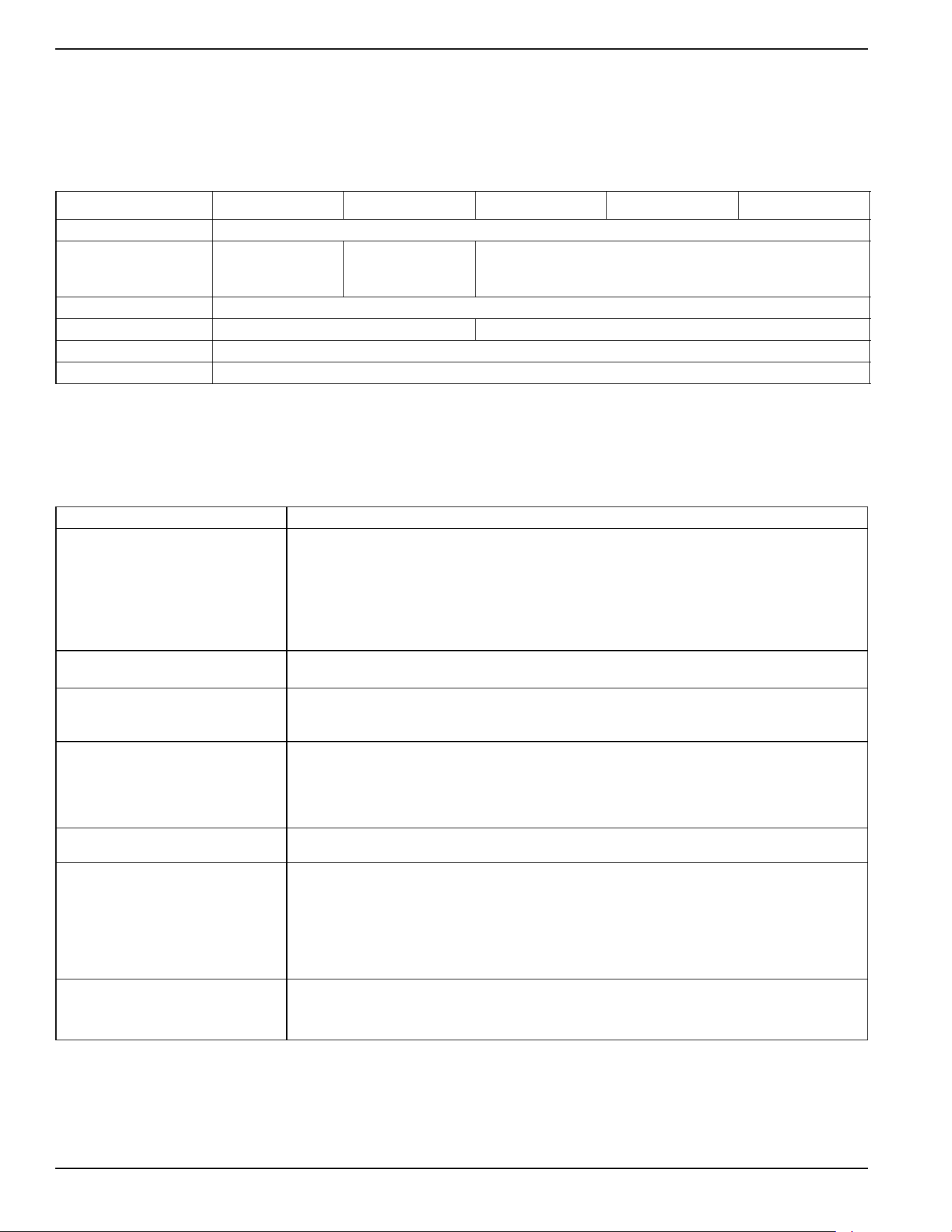
Use this page to record important information about your generator set.
Record the information found on your unit data label on this
page. See
General Information for the location of the unit
data label. The unit has a label plate affixed to the inside
partition, to the left of the control panel console as shown in
Figure 2-1 or Figure 2-2. See Operation for directions on
how to open the top lid and remove the front panel.
When contacting an Independent Authorized Service Dealer
(IASD) about parts and service, always supply the complete
model and serial numbers of the unit.
Operation and Maintenance: Proper maintenance and care
of the generator ensures a minimum number of problems
and keeps operating expenses at a minimum. It is the
operator’s responsibility to perform all safety checks, to
verify all maintenance for safe operation is performed
promptly, and to have the equipment checked periodically by
an IASD. Normal maintenance, service, and replacement of
parts are the responsibility of the owner/operator and are not
considered defects in materials or workmanship within the
terms of the warranty. Individual operating habits and usage
may contribute to the need for additional maintenance or
service.
When the generator requires servicing or repairs, Generac
recommends contacting an Independent Authorized Service
Dealer for assistance. Authorized service technicians are
factory–trained and are capable of handling all service
needs. To locate the nearest Independent Authorized
Service Dealer, please visit the dealer locator at:
www.generac.com/Service/DealerLocator/.
Model:
Serial:
Production Date:
Volts:
LPV Amps:
NG Amps:
Hz:
Phase:
Controller P/N:
STA MAC ID:
SSID:
(000393)
WARNING
Operating, servicing and maintaining this
equipment can expose you to chemicals
including engine exhaust, carbon monoxide,
phthalates, and lead, which are known to the
State of California to cause cancer and birth
defects or other reproductive harm. To
minimize exposure, avoid breathing exhaust,
do not idle the engine except as necessary,
service your equipment in a well-ventilated
area and wear gloves or wash your hands
frequently when servicing your equipment.
For more information go to
www.P65Warnings.ca.gov.

Owner’s Manual for 60 Hz Air-Cooled Generators iii
Section 1: Safety Information
Introduction ..........................................................1
Read This Manual Thoroughly ....................................1
Safety Rules .........................................................1
How to Obtain Service .................................................2
General Hazards ..................................................2
Exhaust Hazards .........................................................3
Electrical Hazards .......................................................3
Fire Hazards ................................................................4
Explosion Hazards ......................................................4
Battery Hazards ...........................................................5
Section 2: General Information
The Generator ......................................................7
Data Decals ..........................................................9
Specifications ....................................................10
Generator ..................................................................10
Engine .......................................................................10
Protection Systems ...........................................11
Emission Information ........................................11
Fuel Requirements ............................................11
Battery Requirements .......................................11
Battery Charger ..................................................11
Engine Oil Requirements ..................................11
Activating the Generator ...................................12
Wi-Fi Module ......................................................12
Replacement Parts ............................................12
Accessories ........................................................12
Section 3: Operation
Site Prep Verification ........................................ 13
Generator Enclosure ......................................... 13
Opening the Lid .........................................................13
Removing the Front Access Panel ............................13
Intake Side Panel Removal .......................................14
Main Line Circuit Breaker (Generator Disconnect) ....14
LED Indicator Lights ..................................................14
Auxiliary Shutdown Switch .............................. 15
Control Panel Interface ..................................... 15
Using the AUTO/OFF/MANUAL Interface ........ 15
Interface Menu Displays ................................... 16
LCD Panel .................................................................16
Menu System Navigation ..........................................18
Setting the Exercise Timer ............................... 20
Battery Charger ................................................. 20
Manual Transfer Operation ............................... 21
Transfer to Generator Power Source ........................21
Transfer to Utility Power Source ................................22
Automatic Transfer Operation ......................... 22
Automatic Sequence of Operation .................. 22
Utility Failure ..............................................................22
Cranking ....................................................................22
Cold Smart Start ........................................................23
Load Transfer ............................................................23
Shutting Generator Down While Under Load
Or During A Utility Outage ................................ 23
Table of Contents

Table of Contents
iv Owner’s Manual for 60 Hz Air-Cooled Generators
Section 4: Maintenance
Maintenance .......................................................25
Preparing for Maintenance ...............................25
Performing Scheduled Maintenance ................25
Service Schedule ...............................................26
Maintenance Log ...................................................... 26
Checking Engine Oil Level ................................27
Engine Oil Requirements .......................................... 27
Changing the Oil and Oil Filter .........................28
Servicing the Air Cleaner ..................................28
Spark Plug(s) ......................................................29
Valve Clearance Adjustment ............................29
Check Valve Clearance ............................................ 29
Adjust Valve Clearance ............................................. 30
Battery Maintenance ..........................................31
Cleaning the Sediment Trap .............................32
Post Maintenance Checks ................................32
Perform Leak Test .............................................33
Attention After Submersion ..............................33
Corrosion Protection .........................................33
Remove From, and Return To Service
Procedure ...........................................................34
Remove From Service .............................................. 34
Return to Service ...................................................... 34
Section 5: Troubleshooting / Quick
Reference Guide
Generator Troubleshooting ..............................35
Quick Reference Guide .....................................37
Safety Information
Owner’s Manual for 60 Hz Air-Cooled Generators 1
Section 1: Safety Information
Introduction
Thank you for purchasing this compact, high
performance, air-cooled, engine-driven generator. It is
designed to automatically supply electrical power to
operate critical loads during a utility power failure.
This unit is factory installed in an all-weather, metal
enclosure intended exclusively for outdoor installation.
This generator will operate using either vapor withdrawn
liquid propane (LP) or natural gas (NG).
NOTE: This generator is suitable for supplying typical
residential loads such as induction motors (sump pumps,
refrigerators, air conditioners, furnaces, etc.), electronic
components (computer, monitor, TV, etc.), lighting loads,
and microwaves, when sized properly. This unit is
equipped with a Wi-Fi® module, which enables the
generator owner to monitor generator status from
anywhere he or she has Internet access.
NOTE: Wi-Fi® is a registered trademark of Wi-Fi
Alliance®.
The information in this manual is accurate based on
products produced at the time of publication. The
manufacturer reserves the right to make technical
updates, corrections, and product revisions at any time
without notice.
Read This Manual Thoroughly
Study this manual carefully before installing, operating, or
servicing this equipment. Become familiar with this
owner’s manual and with the unit. The generator can
operate safely, efficiently, and reliably only if it is properly
installed, operated, and maintained. Many accidents are
caused by failing to follow simple and fundamental rules
or precautions.
If any section of this manual is not understood, contact
the nearest Independent Authorized Service Dealer
(IASD) for starting, operating, and servicing procedures.
This manual must be used in conjunction with the
appropriate installation manual and Wi-Fi manual.
SAVE THESE INSTRUCTIONS: The manufacturer
suggests this manual and the rules for safe operation be
copied and posted near the unit installation site. Safety
should be stressed to all operators and potential
operators of this equipment.
Safety Rules
The manufacturer cannot anticipate every possible cir-
cumstance that might involve a hazard. The alerts in this
manual, and on tags and decals affixed to the unit, are
not all inclusive. If using a procedure, work method, or
operating technique that the manufacturer does not spe-
cifically recommend, verify that it is safe for others and
does not render the equipment unsafe.
Throughout this publication, and on tags and decals
affixed to the unit, DANGER, WARNING, CAUTION, and
NOTE blocks are used to alert personnel to special
instructions about a particular operation that may be
hazardous if performed incorrectly or carelessly. Observe
them carefully. Alert definitions are as follows:
NOTE: Notes contain additional information important to
a procedure and will be found within the regular text of
this manual.
These safety alerts cannot eliminate the hazards that
they indicate. Common sense and strict compliance with
the special instructions while performing the action or
service are essential to preventing accidents.
The operator is responsible for proper and safe use of
the equipment. The manufacturer strongly recommends
that if the operator is also the owner, to read the owner’s
manual and thoroughly understand all instructions before
using this equipment. The manufacturer also strongly
recommends instructing other users to properly start and
operate the unit. This prepares them if they need to
operate the equipment in an emergency.
(000100a)
WARNING
Consult Manual. Read and understand manual
completely before using product. Failure to
completely understand manual and product
could result in death or serious injury.
(000001)
DANGER
Indicates a hazardous situation which, if not avoided,
will result in death or serious injury.
(000002)
WARNING
Indicates a hazardous situation which, if not avoided,
could result in death or serious injury.
(000003)
CAUTION
Indicates a hazardous situation which, if not avoided,
could result in minor or moderate injury.
Safety Information
2 Owner’s Manual for 60 Hz Air-Cooled Generators
How to Obtain Service
Contact an IASD for assistance when the generator requires
servicing or repairs. Service technicians are factory-trained
and are capable of handling all service needs. Please visit
the dealer locator at:
www.generac.com/Service/
DealerLocator/
to locate the nearest IASD.
When contacting a dealer about parts and service,
always supply the complete model and serial numbers of
the unit as given on its data plate (decal), which is
located on the generator. See
Figure 2-1 or Figure 2-2
for decal location. Record the model and serial numbers
in the spaces provided on the inside front cover of this
manual.
General Hazards
(000190)
DANGER
Loss of life. Property damage. Installation must always
comply with applicable codes, standards, laws and
regulations. Failure to do so will result in death
or serious injury.
Automatic start-up. Disconnect utility power and
render unit inoperable before working on unit.
Failure to do so will result in death or serious injury.
(000191)
DANGER
(000209b)
WARNING
Loss of life. This product is not intended to
be used in a critical life support application.
Failure to adhere to this warning could result
in death or serious injury.
WARNING
Equipment damage. This unit is not intended for use as a
prime power source. It is intended for use as an intermediate
power supply in the event of temporary power outage only.
Doing so could result in death, serious injury, and
equipment damage.
(000247a)
(000130)
WARNING
Accidental Start-up. Disconnect the negative battery
cable, then the positive battery cable when working
on unit. Failure to do so could result in death
or serious injury.
(000182a)
WARNING
Equipment damage. Only qualified service personnel may
install, operate, and maintain this equipment. Failure to follow
proper installation requirements could result in death, serious
injury, and equipment or property damage.
(000187)
WARNING
Electrocution. Potentially lethal voltages are generated
by this equipment. Render the equipment safe before
attempting repairs or maintenance. Failure to do so
could result in death or serious injury.
(000155a)
WARNING
Electric shock. Only a trained and licensed electrician
should perform wiring and connections to unit. Failure
to follow proper installation requirements could result in
death, serious injury, and equipment or property damage.
(000115)
WARNING
Moving Parts. Do not wear jewelry when
starting or operating this product. Wearing
jewelry while starting or operating this product
could result in death or serious injury.
(000111)
WARNING
Moving Parts. Keep clothing, hair, and
appendages away from moving parts. Failure
to do so could result in death or serious injury.
(000108)
WARNING
Hot Surfaces. When operating machine, do not
touch hot surfaces. Keep machine away from
combustibles during use. Hot surfaces could
result in severe burns or fire.
(000146)
WARNING
Equipment and property damage. Do not alter
construction of, installation, or block ventilation for
generator. Failure to do so could result in unsafe
operation or damage to the generator.
WARNING
Risk of injury. Do not operate or service this machine
if not fully alert. Fatigue can impair the ability to service
this equipment and could result in death or serious
injury.
(000215)
Safety Information
Owner’s Manual for 60 Hz Air-Cooled Generators 3
•
Inspect the generator regularly, and contact the
nearest IASD for parts needing repair or replacement.
Exhaust Hazards
• The generator must be installed and operated
outdoors only.
Electrical Hazards
WARNING
Environmental Hazard. Always recycle batteries at an
official recycling center in accordance with all local
laws and regulations. Failure to do so could result in
environmental damage, death or serious injury.
(000228)
WARNING
Injury and equipment damage. Do not use generator
as a step. Doing so could result in falling, damaged
parts, unsafe equipment operation, and could result
in death or serious injury.
(000216)
Asphyxiation. Running engines produce
carbon monoxide, a colorless, odorless,
poisonous gas. Carbon monoxide, if not
avoided, will result in death or serious injury.
(000103)
DANGER
(000178a)
Asphyxiation. Always use a battery operated carbon
monoxide alarm indoors and installed according to
the manufacturer’s instructions. Failure to do so
could result in death or serious injury.
WARNING
(000146)
WARNING
Equipment and property damage. Do not alter
construction of, installation, or block ventilation for
generator. Failure to do so could result in unsafe
operation or damage to the generator.
(000144)
DANGER
Electrocution. Contact with bare wires,
terminals, and connections while generator
is running will result in death or serious injury.
(000150)
DANGER
Electrocution. Never connect this unit to the electrical
system of any building unless a licensed electrician
has installed an approved transfer switch. Failure to
do so will result in death or serious injury.
(000237)
DANGER
Electrical backfeed. Use only approved switchgear to
isolate generator from the normal power source.
Failure to do so will result in death, serious injury,
and equipment damage.
(000152)
DANGER
Electrocution. Verify electrical system is
properly grounded before applying power.
Failure to do so will result in death or serious
injury.
(000188)
DANGER
Electrocution. Do not wear jewelry while
working on this equipment. Doing so will
result in death or serious injury.
(000104)
DANGER
Electrocution. Water contact with a power
source, if not avoided, will result in death
or serious injury.
(000145)
DANGER
Electrocution. In the event of electrical accident,
immediately shut power OFF. Use non-conductive
implements to free victim from live conductor. Apply
first aid and get medical help. Failure to do so will
result in death or serious injury.
Safety Information
4 Owner’s Manual for 60 Hz Air-Cooled Generators
Fire Hazards
• Comply with regulations the Occupational Safety
and Health Administration (OSHA) has
established. Also verify the generator is installed in
accordance with the manufacturer’s instructions
and recommendations. Following proper
installation, do nothing that might alter a safe
installation and render the unit in noncompliance
with the aforementioned codes, standards, laws,
and regulations.
Explosion Hazards
WARNING
Fire hazard. Do not obstruct cooling and
ventilating airflow around the generator. Inadequate
ventilation could result in fire hazard, possible
equipment damage, death or serious injury.
(000217)
WARNING
Fire and explosion. Installation must comply
with all local, state, and national electrical
(000218)
building codes. Noncompliance could result in unsafe
operation, equipment damage, death or serious injury.
WARNING
Fire hazard. Use only fully-charged fire
(000219)
extinguishers rated “ABC” by the NFPA. Discharged or
improperly rated fire extinguishers will not extinguish
electrical fires in automatic standby generators.
(000100a)
WARNING
Consult Manual. Read and understand manual
completely before using product. Failure to
completely understand manual and product
could result in death or serious injury.
WARNING
to use required safety equipment could result
in death or serious injury.
(000257)
Electrocution. Refer to local codes and
standards for safety equipment required when
working with a live electrical system. Failure
(000147)
WARNING
Risk of Fire. Unit must be positioned in a
manner that prevents combustible material
accumulation underneath. Failure to do so
could result in death or serious injury.
(000192)
DANGER
Explosion and fire. Fuel and vapors are extremely
flammable and explosive. No leakage of fuel is
permitted. Keep fire and spark away. Failure to do
so will result in death or serious injury.
(000151a)
DANGER
Explosion and fire. Connection of fuel source must be
completed by a qualified professional technician or
contractor. Incorrect installation of this unit will result in
death, serious injury, and property and equipment damage.
(000174)
DANGER
Risk of fire. Allow fuel spills to completely dry
before starting engine. Failure to do so will
result in death or serious injury.
(000110)
WARNING
Risk of Fire. Hot surfaces could ignite
combustibles, resulting in fire. Fire could
result in death or serious injury.

Safety Information
Owner’s Manual for 60 Hz Air-Cooled Generators 5
Battery Hazards
Always recycle batteries in accordance with local laws
and regulations. Contact your local solid waste collection
site or recycling facility to obtain information on local
recycling processes. For more information on battery
recycling, visit the Battery Council International website
at:
http://batterycouncil.org
(000188)
DANGER
Electrocution. Do not wear jewelry while
working on this equipment. Doing so will
result in death or serious injury.
(000162)
WARNING
Explosion. Do not dispose of batteries in a fire. Batteries
are explosive. Electrolyte solution can cause burns and
blindness. If electrolyte contacts skin or eyes, flush with water
and seek immediate medical attention.
(000137a)
WARNING
Explosion. Batteries emit explosive gases while charging.
Keep fire and spark away. Wear protective gear when
working with batteries. Failure to do so could result in
death or serious injury.
(000164)
WARNING
Electrical shock. Disconnect battery ground
terminal before working on battery or battery
wires. Failure to do so could result in death
or serious injury.
(000138a)
WARNING
(000163a)
WARNING
Risk of burn. Do not open or mutilate batteries.
Batteries contain electrolyte solution which can
cause burns and blindness. If electrolyte contacts
skin or eyes, flush with water and seek immediate
medical attention.
WARNING
Environmental Hazard. Always recycle batteries at an
official recycling center in accordance with all local
laws and regulations. Failure to do so could result in
environmental damage, death or serious injury.
(000228)

Safety Information
6 Owner’s Manual for 60 Hz Air-Cooled Generators
This page intentionally left blank.
General Information
Owner’s Manual for 60 Hz Air-Cooled Generators 7
Section 2: General Information
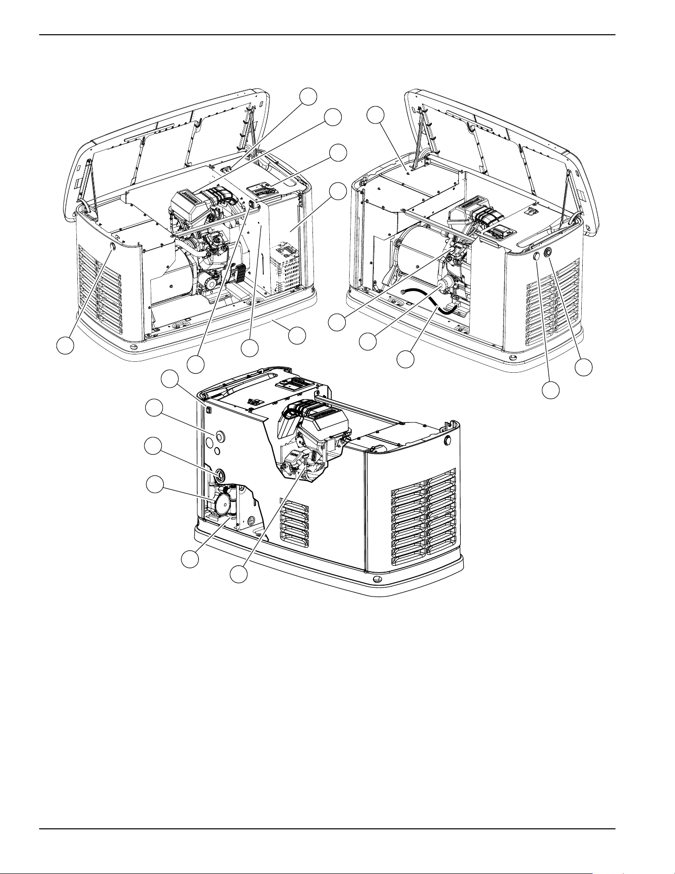
The Generator
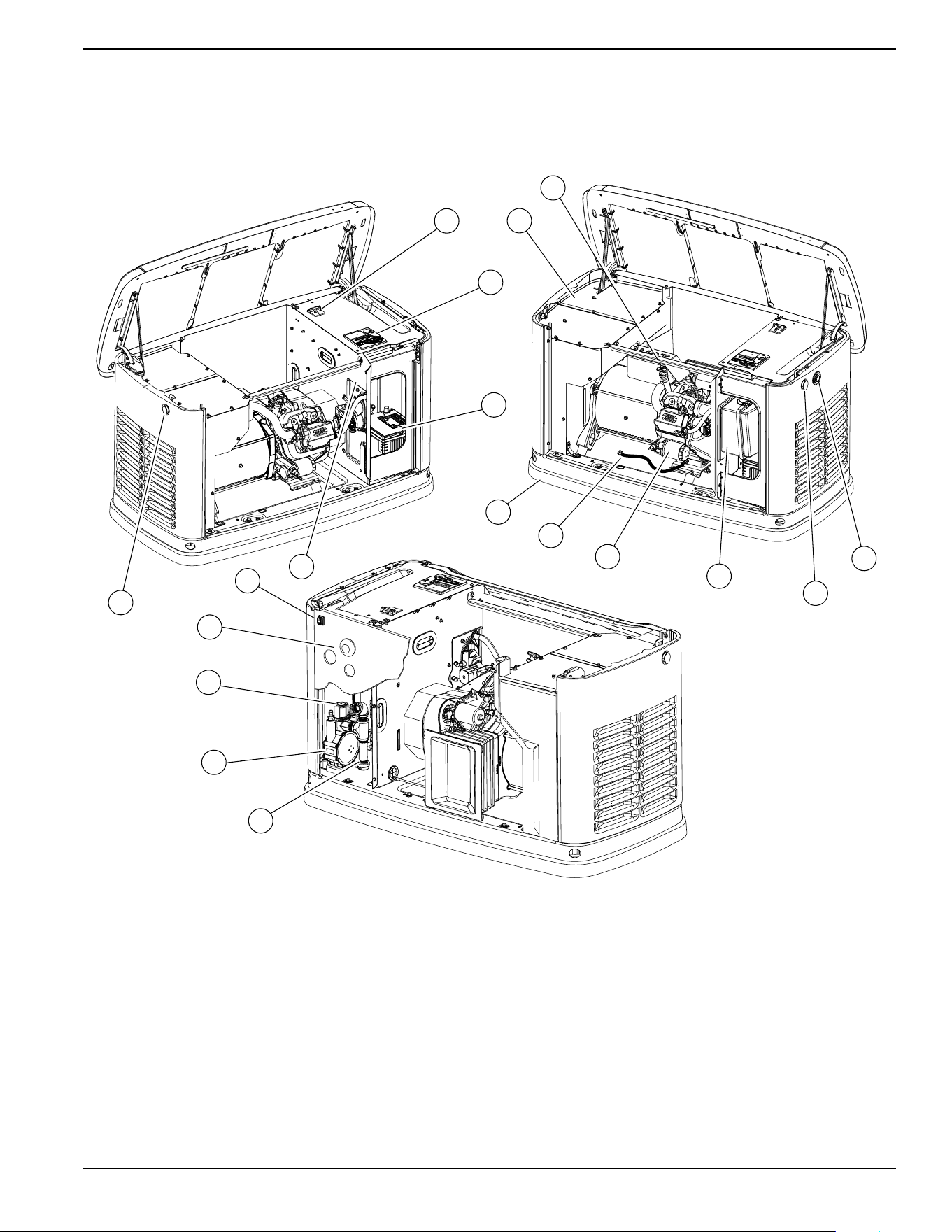
Figure 2-1. 9kW—Components and Control Locations
A. Lock with Cover F. Oil Fill Cap/Dipstick K. Oil Drain Hose O. Fuel Inlet
B. Main Line Circuit
Breaker (Generator
Disconnect)
G. Status LED Indicators L. Composite Base P. Wi-Fi Module
C. Control Panel H. Airbox with Air Cleaner M. Sediment Trap Q. Data Decal Location
D. Battery Compartment
(Battery not supplied)
J. Oil Filter N. Fuel Regulator R. Auxiliary Shutdown
Switch
E. Exhaust Enclosure
F
001818
M
N
O
P
A
Q
D
C
B
E
L
K
J
H
A
G
R
General Information
8 Owner’s Manual for 60 Hz Air-Cooled Generators
Figure 2-2. 11kW–22kW—Components and Control Locations
A. Lock with Cover F. Exhaust Enclosure L. Composite Base Q. Wi-Fi Module
B. Main Line Circuit
Breaker (Generator
Disconnect)
G. Status LED Indicators M. Oil Dipstick R. Data Decal Location
C. Airbox with Air Cleaner H. Oil Drain N. Sediment Trap S. Auxiliary Shutdown
Switch (all models)
D. Control Panel J. Oil Fill Cap O. Fuel Regulator T. Auxiliary Shutdown
Switch (16kW–22kW)
E. Battery Compartment
(Battery not supplied)
K. Oil Filter P. Fuel Inlet
001786
N
M
O
P
Q
G
K
J
F
L
R
E
A
D
C
B
A
H
T
S
General Information
Owner’s Manual for 60 Hz Air-Cooled Generators 9
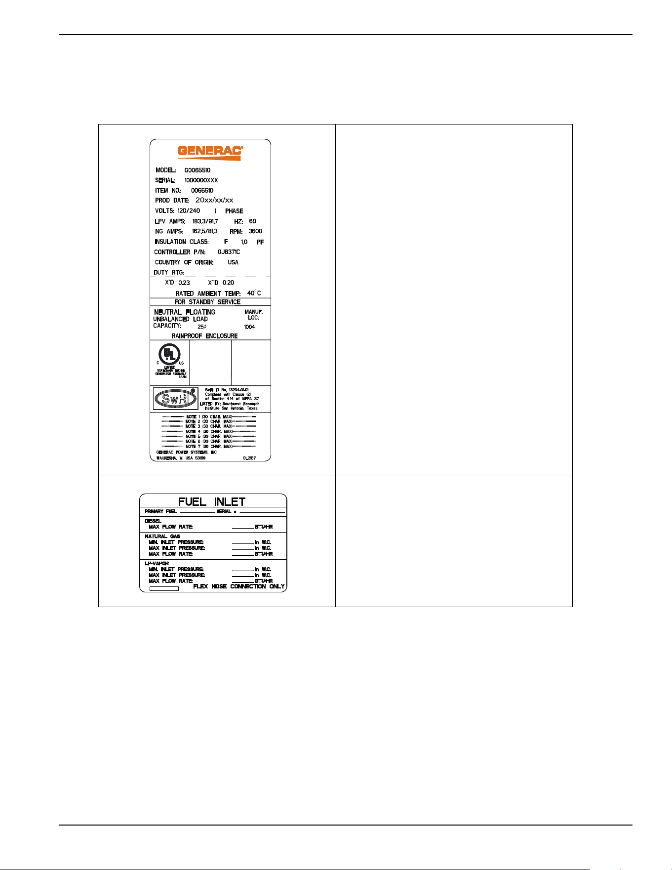
Data Decals
Two decals on the generator provide information about
the unit itself and required fuel inlet pressure for proper
operation.
Model Data Decal
Includes important information about the
unit including:
• model number
• serial number
• production date
•voltage
• frequency
•amps
• country of origin
• rated ambient temperature.
The model data decal also displays
certification symbols by Underwriter’s
Laboratory (UL) and the Southwest Research
Institute (SwRI).
Fuel Inlet Pressure
Displays unit serial number, along with
minimum and maximum inlet pressures for
natural gas (NG) and liquid propane (LP)
supply. Space is provided for the installer to
enter maximum flow rates based on installed
pipe sizes and lengths.
General Information
10 Owner’s Manual for 60 Hz Air-Cooled Generators
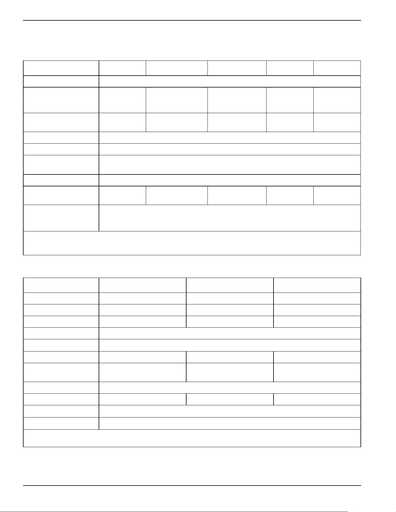
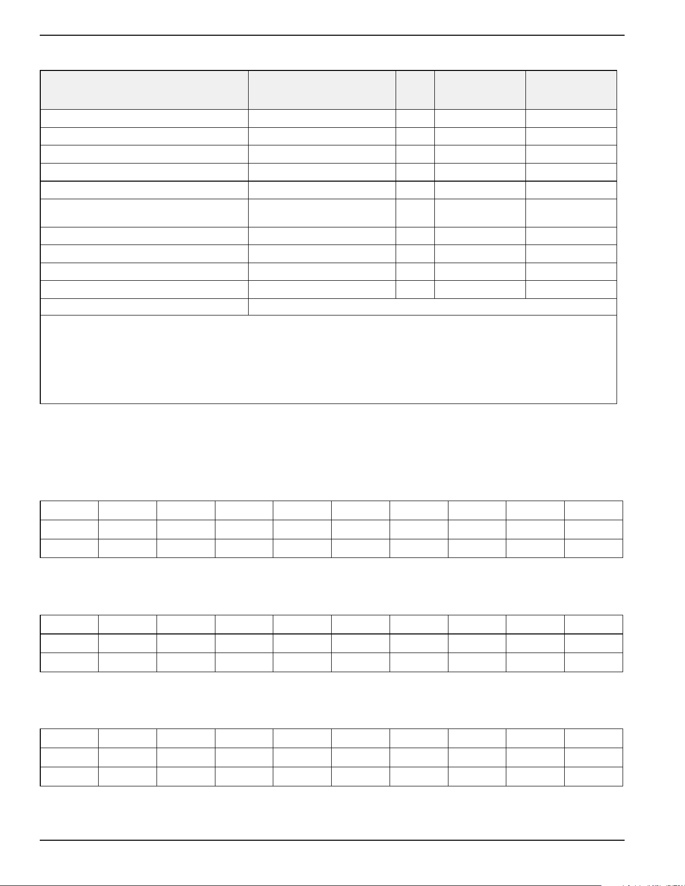
Specifications
Generator
Engine
A detailed specification sheet for your particular generator is available from your local Independent Authorized Service
Dealer (IASD).
Model 9 kW 11 kW 16 kW 20 kW 22 kW
Rated Voltage 240
Rated Maximum Load
Current (Amps) at Rated
Voltage with LP*
37.5 45.8 66.6 83.3 91.7
Main Line Circuit Breaker
(Generator Disconnect)
40 Amp 50 Amp 70 Amp 90 Amp 100 Amp
Phase 1
Rated AC Frequency 60 Hz
Battery Requirement
(Field supplied)
12 volts, Group 26R-540CCA Minimum or Group 35AGM-650CCA Minimum
(see
Replacement Parts)
Enclosure Aluminum
Weight (lb/kg)
(without battery)
340/154 348/158 409/186 448/203 466/211
Normal Operating Range
This unit is tested in accordance to UL 2200 standards with an operating temperature of -20 °F (-29 °C) to
122 °F (50 °C). For areas where temperatures fall below 32 °F (0 °C) a cold weather kit is recommended.
When operated above 77 °F (25 °C), there may be a decrease in engine power. See
Engine
.
These generators are rated in accordance with UL 2200, Safety Standard for Stationary Engine Generator Assemblies, and CSA-C22.2 No. 100-04
Standard for Motors and Generators.
* Natural gas ratings will depend on specific fuel joules/BTU content. Typical derates are between 10-20% off the LP gas rating.
Model 9 kW 11 kW 16/20/22 kW
Type of Engine G-Force 400 Series G-Force 500 Series G-Force 1000 Series
Number of Cylinders 1 2 2
Displacement 426 cc 530 cc 999 cc
Cylinder Block
Aluminum with cast iron sleeve
Recommended Spark Plug
See
Replacement Parts
Spark Plug Gap 0.020 in (0.508 mm) 0.030 in (0.76 mm) 0.040 in (1.02 mm)
Valve Clearance
0.002–0.004 in
(0.05–0.1 mm)
0.002–0.004 in
(0.05–0.1 mm)
0.002–0.004 in
(0.05–0.1 mm)
Starter 12 VDC
Oil Capacity Including Filter Approx. 1.1 qt (1.03 L) Approx. 1.7 qt (1.6 L) Approx. 1.9 qt (1.8 L)
Recommended Oil Filter
See
Replacement Parts
Recommended Air Filter
See
Replacement Parts
Engine power is subject to and limited by such factors as fuel BTU/joules, ambient temperature, and altitude. Engine power decreases approximately
3.5% for each 1000 ft (304.8 m) above sea level, and also will decrease about 1% for each 10 °F (6 °C) above 60 °F (15 °C) ambient temperature.
General Information
Owner’s Manual for 60 Hz Air-Cooled Generators 11
Protection Systems
The generator may need to run for long periods of time
with no operator present to monitor engine or generator
conditions. The generator is equipped with protection
systems to automatically shut down the unit to protect
against potentially damaging conditions. Some of these
systems include:
Alarms:
Warnings:
The control panel contains a display alerting the operator
when a fault condition occurs. The above list is not all-
inclusive. See
Operation for more information about
alarms and control panel operation.
NOTE: A warning indicates a condition on the generator
which should be addressed, but will not shut down the
generator. An alarm shuts down the generator to protect
the system from any damage. In the event of an alarm,
an owner can clear the alarm and restart the generator
prior to contacting an IASD. Contact an IASD if the
intermittent issue occurs again.
Emission Information
The United States Environmental Protection Agency (US
EPA) (and California Air Resources Board (CARB), for
engines/equipment certified to California standards)
requires that this engine/equipment complies with
exhaust and evaporative emissions standards. Locate
the emissions compliance decal on the engine to
determine applicable standards. For emissions warranty
information, please reference the included emissions
warranty. Follow the maintenance specifications in
Maintenance to ensure the engine complies with
applicable emissions standards for the duration of the
product’s life.
This generator is certified to operate on liquid propane
vapor fuel or pipeline natural gas.
The Emission Control System code is EM (Engine
Modification). The Emission Control System on this
generator consists of the following:
:
Fuel Requirements
The engine has been fitted with a dual fuel carburetion
system. The unit will run on natural gas or LP gas
(vapor), but it has been factory set to run on natural gas.
The fuel system will be configured for the available fuel
source during installation.
Recommended fuels should have a BTU content of at least
1000 BTUs per ft
3
(37.26 megajoules per m
3
) for natural
gas, or at least 2500 BTUs per ft
3
(93.15 megajoules per
m
3
) for LP gas (vapor).
NOTE:
If converting to LP gas from natural gas, a
minimum LP tank size of 250 gal (946 L) is recommended.
See the installation manual for complete procedures and
details.
Battery Requirements
12 volts, Group 26R-540CCA minimum or Group 35AGM-
650CCA minimum (not included with unit.) See
Maintenance
for proper battery maintenance procedures.
Battery Charger
The battery charger is integrated into the control panel
module in all models. It operates as a smart charger,
ensuring output charging levels are safe and
continuously optimized to promote maximum battery life.
A kit is provided to install a fuse in the transfer switch for
the T1 battery charger connection. Follow the installation
instructions provided with the kit.
NOTE: Do not use external battery chargers.
Engine Oil Requirements
See
Engine Oil Requirements in the Maintenance
section for proper oil viscosity.
• High Temperature
• Low Oil Pressure
• Overcrank
• Overspeed
• Overvoltage
• Undervoltage
• Overload
• Underspeed
• RPM Sensor Loss
• Controller Fault
• Wiring Error
• Stepper Overcurrent
• Charger Warning
• Charger Missing AC
• Low Battery
• Battery Problem
• Exercise Set Error
• USB Warning
• Download Failure
System Components
Air Induction
- Intake Manifold
- Air Cleaner
Fuel Metering
- Carburetor and Mixer Assembly
- Fuel Regulator
Ignition
- Spark Plug
- Ignition Module
Exhaust
- Exhaust Manifold
- Muffler
(000105)
DANGER
Explosion and Fire. Fuel and vapors are
extremely flammable and explosive. Add fuel
in a well ventilated area. Keep fire and spark
away. Failure to do so will result in death
or serious injury.
General Information
12 Owner’s Manual for 60 Hz Air-Cooled Generators
Activating the Generator
The generator should be activated upon initial start-up.
See the installation manual for complete instructions.
Wi-Fi Module
The generator is equipped with a Wi-Fi module. Refer to
the Wi-Fi module owner’s manual for further instruction.
Replacement Parts
Accessories
NOTE: Performance enhancing accessories are available for air-cooled generators. Contact an IASD or visit
www.generac.com for additional information on replacement parts, accessories, and extended warranties. See also
http://www.ordertree.com/generac/air-cooled-homestandby-generators/.
Description 9 kW 11 kW 16 kW 20 kW 22 kW
26R Exide Battery 0H3421S
Spark Plug
0G0767B
(RC12YC
or equivalent)
0E9368
(RL87YC
or equivalent)
0G0767A
(RC12YC or equivalent)
Oil Filter 070185E
Air Filter 0E9371A 0J8478
Control Panel Fuse 0D7178T
Transfer Switch Fuses Refer to Transfer Switch Manual for part number
Accessory Description
Cold Weather Accessories*—
• Battery Pad Warmer
• Oil Warmer
• Breather Warmer
* each sold separately
• Recommended in areas where temperatures fall below 0 °F (-18 °C).
(Not necessary for use with AGM-style batteries)
• Recommended in areas where temperatures fall below 0 °F (-18 °C).
• Recommended in areas where heavy icing occurs.
Scheduled Maintenance Kit Includes all pieces necessary to perform maintenance on the generator along with oil
recommendations.
Fascia Base Wrap The fascia base wrap snaps together around the bottom of the new air-cooled generators. This
offers a sleek, contoured appearance as well as protection from rodents and insects by covering
the lifting holes located in the base. Requires use of the mounting pad shipped with the generator.
Mobile Link™ Cellular Enabled
Accessory (USA only)
Provides a personalized web portal displaying generator status, maintenance schedule, event
history, and much more. This portal is accessible via computer, tablet, or smart phone. Sends
emails and/or text notifications the moment there is any change in the generator’s status.
Notification settings can be customized to what type of alert is sent and how often. Visit
www.MobileLinkGen.com for more information.
Touch-Up Paint Kit Very important to maintain the look and integrity of the generator enclosure. This kit includes
touch-up paint and instructions.
Extended Warranty Coverage Extend the generator warranty coverage by purchasing extended warranty coverage. Covers both
parts and labor. Extended coverage can be purchased within 12 months of the end-user’s
purchase date.
This extended coverage is applicable to registered units and end-user proof of purchase must be
available upon request.
Available for Generac
®
and Guardian
®
products.
Not available for Corepower™, PowerPact™, and EcoGen™ products or all international
purchases.
Wi-Fi LP Fuel Level Monitor The Wi-Fi enabled LP fuel level monitor provides constant monitoring of the connected LP fuel
tank. Monitoring the LP tank level is an important step in making sure your generator is ready to
run during an unexpected power failure. Status alerts are available through the Mobile Link™
application informing you when your LP tank needs a refill.
Operation
Owner’s Manual for 60 Hz Air-Cooled Generators 13
Section 3: Operation
Site Prep Verification
The generator must be installed to allow unimpeded airflow
into and out of the generator.
Mechanical and gravity outdoor air intake openings for air
distribution and supply systems must be located not less
than 10 ft (3.05 m) horizontally from the generator
enclosure. See Section 401.4 in the ICC Mechanical
Code for additional information.
Verify all shrubs or tall grasses within 3 ft (0.91 m) of the
intake and discharge louvers on the sides of the
enclosure have been removed. Install the generator on
high ground where water levels will not rise and
endanger it. This unit should not operate in or be
subjected to standing water. Verify all potential water
sources such as water sprinklers, roof run-off, rain gutter
downspouts, and sump pump discharges are directed
away from the generator enclosure.
Generator Enclosure
Enclosure lid is locked prior to shipment. A set of keys is
attached to the cardboard on top of the generator. An
additional set of keys is attached to the pallet bracket on
the front intake end of the generator.
NOTE:
Keys provided with this unit are intended for
service personnel use only.
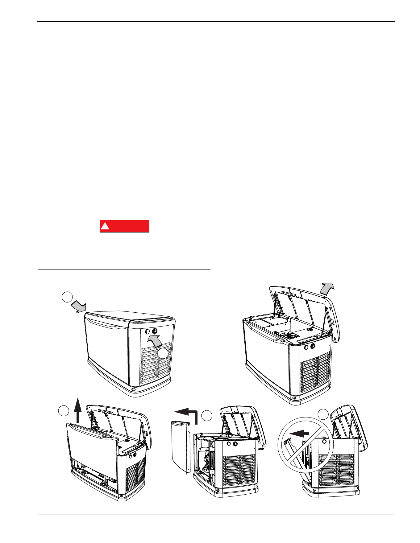
Opening the Lid
Two locks secure the lid—one on each side (A in
Figure 3-
1
). Open the protective rubber cap to access the keyhole,
and press down on the lid above the side lock and unlock
the latch to properly open the lid.
Repeat for the other side. The lid may appear stuck if
pressure is not applied from the top.
Always verify the side locks are unlocked before
attempting to lift the lid.
Removing the Front Access Panel
Remove the front access panel by lifting it straight up and
out once the lid is open.
Always lift the front access panel straight up before pulling
it away from the enclosure (B and C in
Figure 3-1
). Do not
pull the panel away from the enclosure before lifting up (D
in
Figure 3-1
).
Figure 3-1. Side Lock Location and Front Panel Removal
Automatic start-up. Disconnect utility power and
render unit inoperable before working on unit.
Failure to do so will result in death or serious injury.
(000191)
DANGER
001797
A
A
B
C
D
Operation
14 Owner’s Manual for 60 Hz Air-Cooled Generators
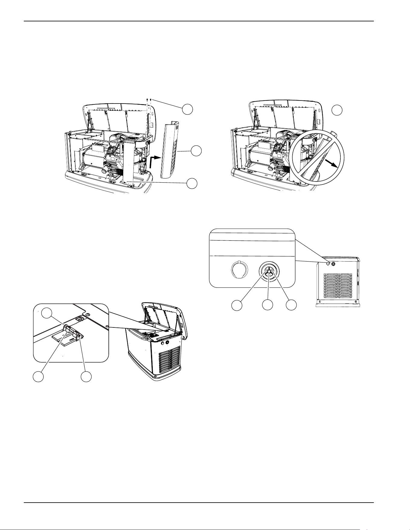
Intake Side Panel Removal
See
Figure 3-2. The intake side panel (A) must be
removed to access the battery compartment, fuel
regulator, and sediment trap.
1. Raise lid and remove front panel.
2. Use a hex key to remove two mounting screws (B)
and L-bracket screw (C).
3. Lift intake panel up and away from the generator.
NOTE: Always lift intake side panel straight up before
pulling away from enclosure. Do not pull panel away from
the enclosure before lifting up (D).
Figure 3-2. Intake Side Panel Removal
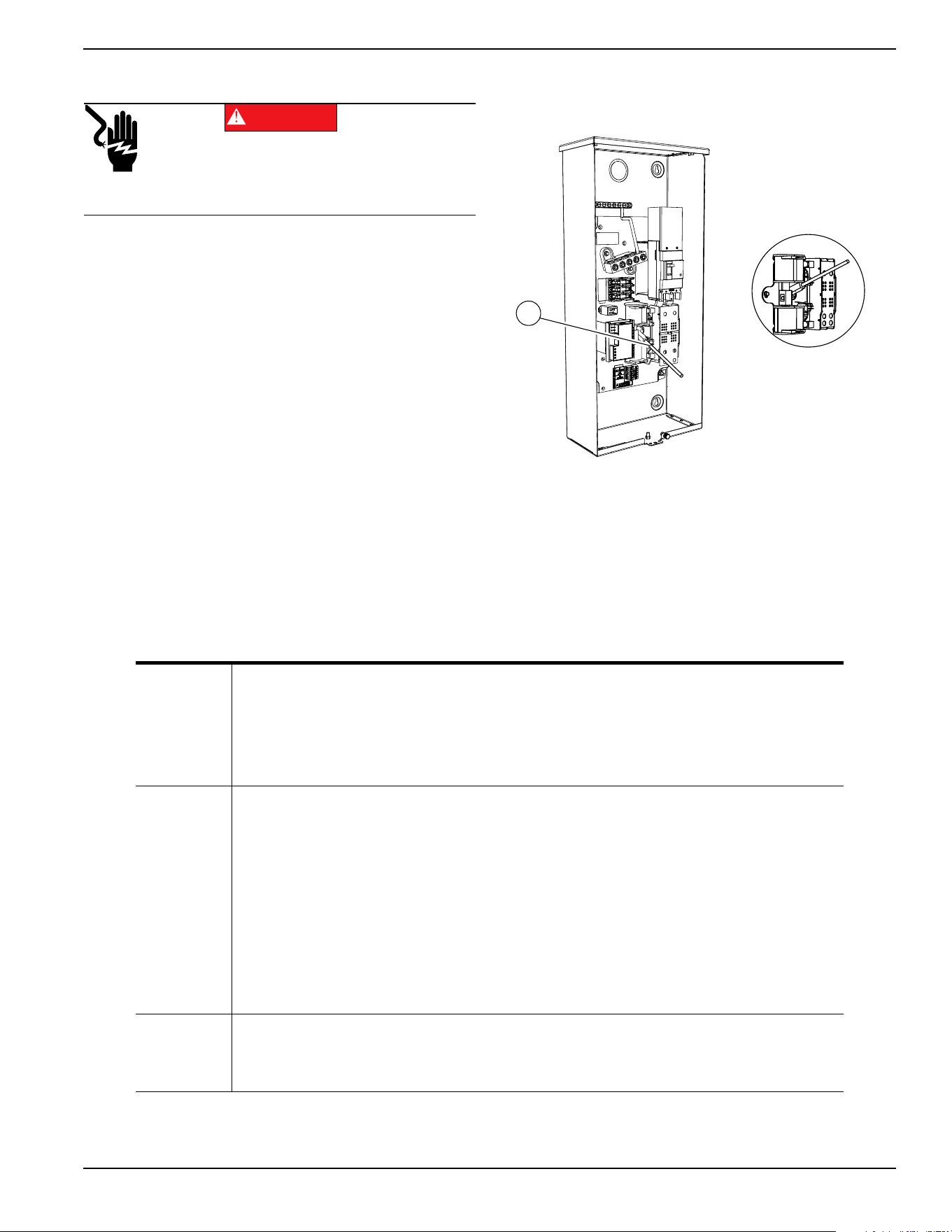
Main Line Circuit Breaker (Generator
Disconnect)
This is a 2-pole breaker rated according to relevant
specifications. See “A” in
Figure 3-3.
The breaker can be locked in the OFF (OPEN) position
for security. Use an appropriately-sized padlock (not
included) with a shackle long enough to pass through
both lock tabs (B).
Figure 3-3. Main Breaker
NOTE: DO NOT lock out the MLCB during normal
generator operation. Doing so will compromise automatic
standby functionality.
LED Indicator Lights
Figure 3-4. LED Indicator Lights
See
Figure 3-4. Three LEDs are visible behind a
translucent lens on the generator side panel. These
LEDs indicate generator operating status.
• Green LED “Ready” light (A) is illuminated when
utility is present and the control panel is in AUTO
mode. The LED flashes when the automatic
transfer switch converts to generator power during
a utility power outage.
• Red LED “Alarm” light (B) is illuminated when the
generator is OFF or a fault is detected. Contact an
IASD.
• Yellow LED “Non-Critical Alert” light (C) is
illuminated when maintenance is required.
NOTE: Yellow LED may be illuminated at the same time
as either the red or green LED.
D
002961
B
A
C
001810
BA
B
001791
A
C
B
Operation
Owner’s Manual for 60 Hz Air-Cooled Generators 15
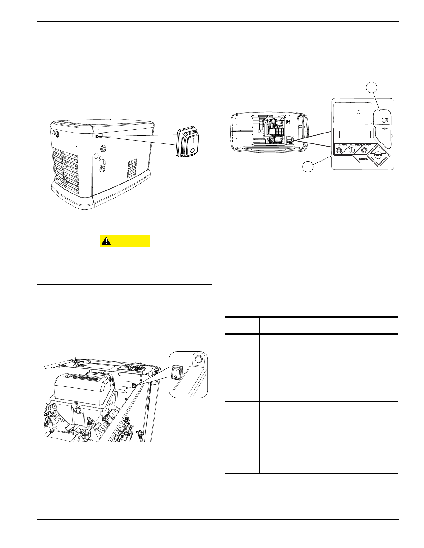
Auxiliary Shutdown Switch
All generators are equipped with an external means of
shutting down the generator which complies with the latest
NEC code requirement. The primary generator shutdown
sequence is described in
Shutting Generator Down
While Under Load Or During A Utility Outage
.
See Figure 3-5. There is an auxiliary shutdown switch on
the exterior of the generator back panel. This switch
shuts down the generator and disables restarts.
Figure 3-5. External Auxiliary Shutdown Switch
(all models)
NOTE: Whenever possible, perform the primary
shutdown procedure before disabling the generator with
the auxiliary shutdown switch.
See
Figure 3-6. 16-22 kW generators also have an
auxiliary shutdown switch located inside the generator.
Figure 3-6. Internal Auxiliary Shutdown Switch (16-22kW)
The generator will not start if either switch is OPEN (O).
The controller displays an “Auxiliary Shutdown” alarm,
and the red LED “Alarm” light illuminates. To clear this
condition, set the switch or switches to CLOSED (I).
Clear the alarm by pressing the OFF mode button, and
then ENTER. The generator can then be placed back in
AUTO or MANUAL mode.
Control Panel Interface
See
Figure 3-7. The control panel interface (A) is located
under the enclosure lid. Verify both the left and right side
locks are unlocked before attempting to lift the lid of the
enclosure. Open the lid as directed in
Opening the Lid.
Figure 3-7. Generator Control Panel
The 7.5A fuse is located beneath the rubber cover (B) to
the right of the control panel.
Verify both left and right side locks are securely out of
the way before closing the unit.
All appropriate panels must be in place during any
operation of the generator. This includes operation by a
servicing technician while conducting troubleshooting
procedures.
Using the AUTO/OFF/MANUAL
Interface
NOTE: Damage caused by mis-wiring of interconnect
wires is not warrantable.
005491
CAUTION
(000399)
Equipment Damage. The auxiliary shutdown switch is
not to be used to power down the unit under normal
operating circumstances. Doing so will result in
equipment damage.
005492
Button Description of Operation
AUTO
Activates fully automatic system operation. It
allows the unit to automatically start and
exercise the generator according to the
exercise timer (see
Setting the Exercise
Timer).
The green LED flashes when the automatic
transfer switch converts to generator power
during a utility power outage.
OFF
Shuts down the engine and prevents automatic
operation of the unit.
MANUAL
Cranks and starts the generator. Transfer to
standby power will not occur unless there is a
utility failure.
The blue LED flashes when the automatic
transfer switch converts to generator power
during a utility power outage.
001798
A
B
Operation
16 Owner’s Manual for 60 Hz Air-Cooled Generators
Interface Menu Displays
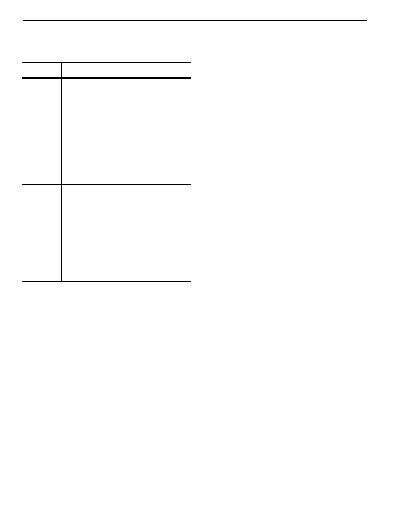
LCD Panel
Feature Description
HOME
page
Default page displayed if no buttons are
pressed for 60 seconds. Normally shows
current status message, and current date and
time. The highest priority active alarm/warning
is automatically posted on this page, as well as
flashing the backlight when such a condition is
detected. In the case of multiple alarms/
warnings, only the first message is displayed.
Press the OFF mode button and then the
ENTER button to clear an alarm or warning.
When “Hours of Protection” is displayed, this
represents the total time the generator has
been monitoring utility supply and ready to
provide backup power if needed.
Display
Backlight
Normally off. The backlight will automatically
illuminate and remain on for 30 seconds if the
operator presses any button.
MAIN
MENU
page
Allows the operator to navigate to all other
pages or sub-menus by using the arrow keys
and the ENTER button. Page can be accessed
at any time with several presses of the
dedicated ESCAPE button. Each press of the
ESCAPE button takes the operator to the
previous menu until the MAIN MENU displays.
This page contains information for History;
Status; Edit; and Debug.

Operation
Owner’s Manual for 60 Hz Air-Cooled Generators 17
This page intentionally left blank.
Operation
18 Owner’s Manual for 60 Hz Air-Cooled Generators
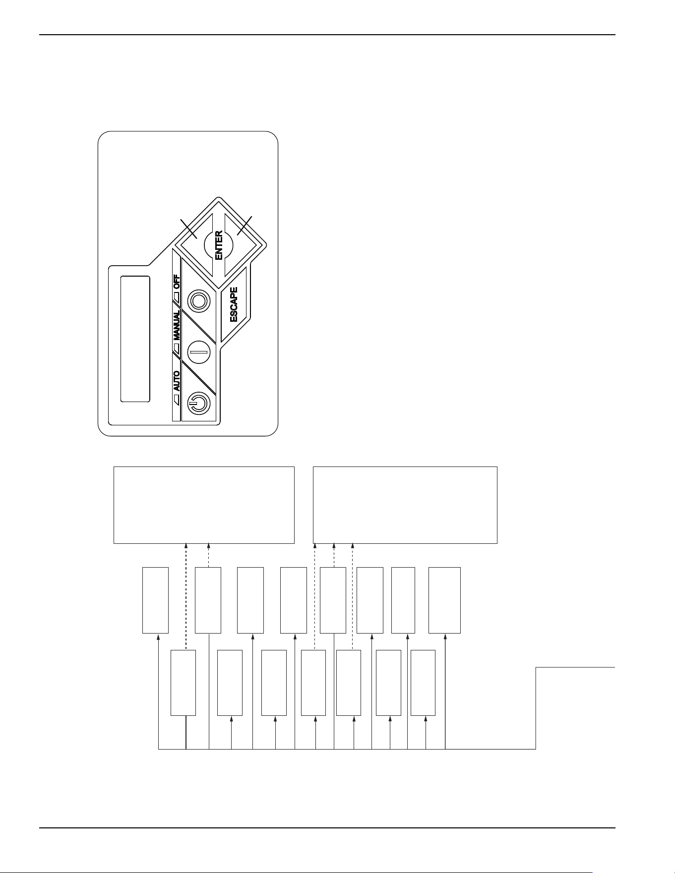
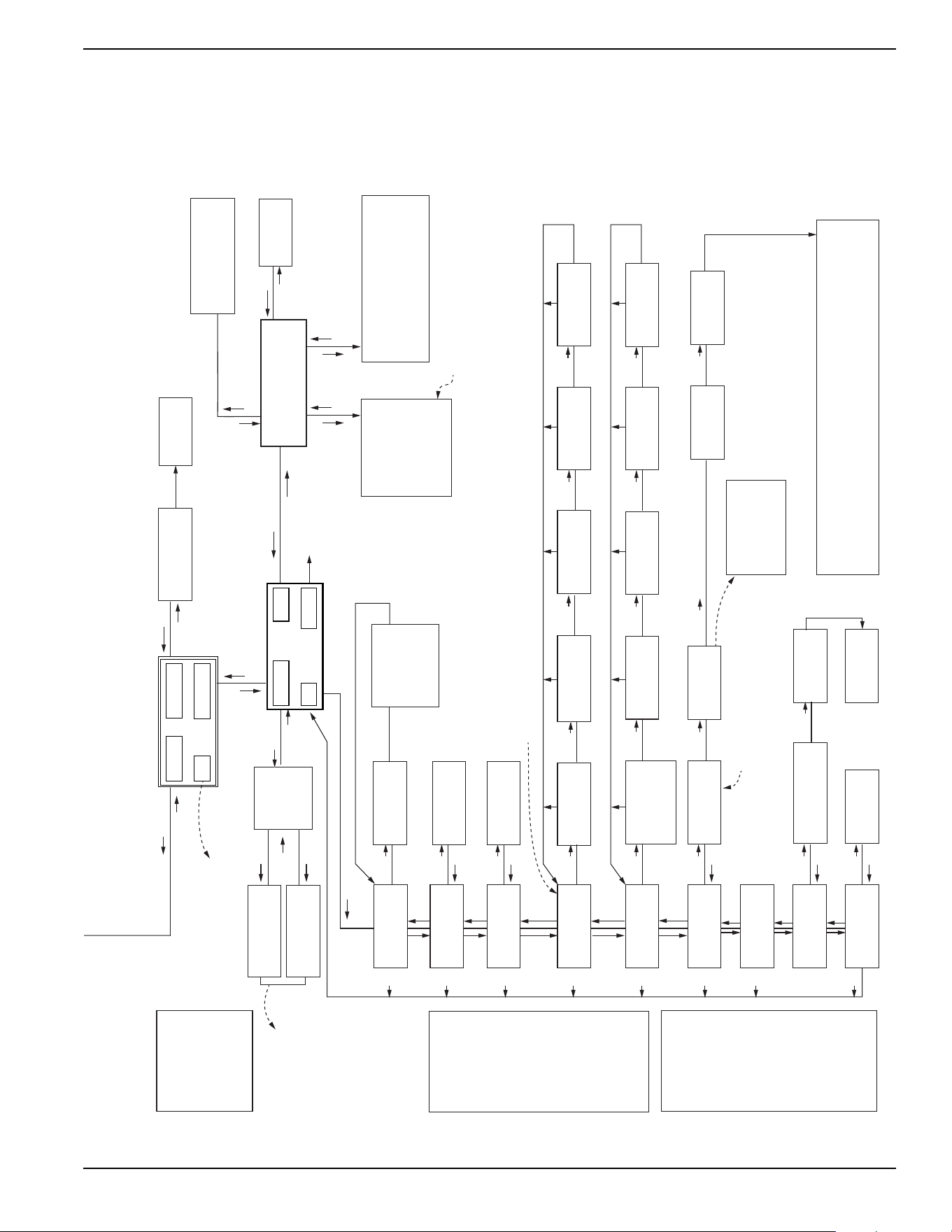
Menu System Navigation
Press the ESCAPE button from any page to access the MENU, You may need to press the ESCAPE button several
times before reaching the MENU page. Navigate to the desired menu by using the ↑/↓ buttons. Press the ENTER
button when the desired menu is displayed and flashing,
Figure 3-8. Navigation Menu
EVOLUTION 2.0 / SYNC 3.0 HSB MENU MAP
Switched to “OFF”
Hours of Protection
0 (H)
Note: Menu functions and features may vary
depending on unit model and firmware revision.
* Hours of Protection and
number of hours will flash
every 5 seconds when
displayed.
*
Ready to Run
Hours of Protection
0 (H)
Utility Loss Delay
Pausing for 13 sec.
Cranking
Attempt # 3
Running in Exercise
Hours of Protection
0 (H)
Running
Cooling Down
Running - Warning
“Warning Message”
Warning Message(s)
Low Battery
Exercise Set Error
Service Schedule A
Service Schedule B
Inspect Battery
Stopping...
FIRMWARE ERROR-9
Fuel Pressure
Battery Problem
Charger Warning
Charger Missing AC
Overload Warning
SEEPROM ABUSE
USB Warning
Download Failure
Overload Warning
No WIFI Module
No WIFI Router Comms
No WIFI Server Comms
Cranking - Warning
“Warning Message”
Alarm Message(s)
High Engine Temp
Low Oil Pressure
Overcrank
Overspeed
RPM Sense Loss
Underspeed
Controller Fault
FIRMWARE ERROR-7
WIRING ERROR
Overvoltage
Undervoltage
Overload Remove Load
Low Volts Remove Load
Stepper Overcurrent
Auxiliary Shutdown
Emergency Stop
Fuse Problem
Loss of Speed Signal
Loss of Serial Link
Stopped - Warning
“Warning Message”
Cranking
Pausing for 13 sec
Running
Hours of Protection
0 (H)
Running
Warming Up
Running - Alarm
“Alarm Message”
Cranking - Alarm
“Alarm Message”
Switched OFF
Hours of Protection
0 (H)
UP ARROW =
+
DOWN ARROW = -
006667
Operation
Owner’s Manual for 60 Hz Air-Cooled Generators 19
Figure 3-9. Navigation Menu
001359
006667
Run Log
EXAMPLE:
Inspect Battery 200 RnHr or 12/27/18
and
Next Maintenance 200 RnHr or 12/27/18
Exercise Time
Å HH:MM Day Frequency Æ
ESC
+
–
++ +
–
ENTER
Current Date/Time
Å 2/12/16 12:22 Æ
ESCESCESCESC
ENTER
ESC
ENTER
ESC
ENTER
ESC
Maint. Log
Run Hrs
Scheduled
Select Month (1-12)
- 2 +
Run Hours (H)
0.0
Select Date (1-31)
- 13 +
Select Year (0-99)
- 13 +
Access
Requires Password
Language
Å English Æ
Fuel Selection
Å NG or LP Æ
Alarm Log
ENTER
ESC
ENTER
ESC
ENTER
ESC
"Battery Maintained"
"Schedule A Serviced"
"Schedule B Serviced"
"Maintenance Reset"
"Inspect Battery"
"Service Schedule A"
"Service Schedule B"
Warning Message(s)
Low Battery
Exercise Set Error
Service Schedule A
Service Schedule B
Inspect Battery
Stopping...
FIRMWARE ERROR-9
Battery Problem
Charger Warning
Charger Missing AC
Overload Cooldown
SEEPROM ABUSE
USB Warning
Download Failure
Overload Warning
No WIFI
Running Manual
Running-Utility Lost
Running–Remote Start
Running–2 Wire Start
Running–Exercise
Switched Off
Stopped - Auto
Select Min (0-59)
- 0 +
Select Hour (0-23)
- 14 +
Select Min (0-59)
- 0 +
Select Hour (0-23)
- 14 +
Quiet Test Mode ?
- YES or NO +
Select Frequency
- WEEKLY +
- BIWEEKLY +
- MONTHLY +
Language
+ English -
Fuel Selection
+ NG or LP -
Cold Smart Start?
Å YES or NO Æ
Cold Smart Start?
- YES or NO +
Language
+ Francais -
+ Espanol -
+ Português -
+ ...... -
Battery Condition
“Good”, “Inspect Battery” or
“Check Battery”
Select Day
- Wednesday +
Generator Activated
Language Update?
Å YES or NO Æ
WIFI Enable
Å YES or NO Æ
WIFI Enable
– YES or NO +
<ENT> LOAD LANGUAGE
<ESC> TO QUIT
ESC
ESC
ESC
ESC
ESC
ESC
ESC
ESC
Current Date/Time
10/09/18 07:40
ESC
ESC
ENTER
ESC
ENTER
ENTER
ENTER
Time Zone
Country/City
XX - XX/XX/XX XX:XX
XXXXX
XX - XX/XX/XX XX:XX
XXXXX
NOTE 1: Last 50 logs
displayed for each
(Alarm Log, Run Log,
Maint. Log).
NOTE 2: Date and time
displayed for each
occurence.
NOTE 3: Error code
displayed for each
Alarm, Error Code
and Alarm Message
swap every 5
seconds.
Battery
NOTE 1: Last 50 maintenance logs displayed.
NOTE 2: Date and time displayed for each
occurence.
(If enabled):
Refer to the Wi-Fi manual for
flow charts relating to Wi-Fi
Only if Wi-Fi is disabled.
Date/Time automatically updates if connected to Wi-Fi.
Firmware Update
Å YES Æ
Current: V 1.01
USB: V 1.05
Are You Sure?
- Yes or No +
Update from:
Å USB or Wi-Fi Æ
Select YES, then press ENTER to continue or ESCAPE to cancel update. During
update process, the Blue “Manual” light flashes, then the Green “Auto” light flashes.
Sequence then repeats. When update is complete, the unit returns to Install Wizard
menu. When the controller powers up, the first screen briefly displays the version number.
When update is complete, remove USB Drive. Then follow the Install Wizard Menu.
Firmware Update
<- Insert USB ->
Possible Message(s):
Corrupted File
Invalid File
File Not Found
Unsupported Device*
* Re-try using a higher quality
USB drive. File names on the USB
cannot have more than 8 characters.
Refer to the Installation Wizard.
SYSTEM
WIFI
DATE/TIME
SUB MENUS
HISTOR
Y
EDIT
MAINT
DEALER
ESC
ENTER
ESC
ENTER
ESC
ENTER
ENTER
USB
ENTER ENTER
ENTER
ENTER
ENTER ENTER
ENTER
ENTER
ENTER
ENTER
Current: V 1.01
USB: V 1.05
Are You Sure?
- Yes or No +
ENTER
ENTER
ENTER
ENTER ENTER
ENTER
ENTER
ESC
ENTER
ESC
ENTER
Alarm Message(s)
High Engine Temp
Low Oil Pressure
Overcrank
Overspeed
RPM Sense Loss
Underspeed
Internal Fault
FIRMWARE ERROR-7
WIRING ERROR
Overvoltage
Undervoltage
Overload Remove Load
Low Volts Remove Load
Stepper Overcurrent
Auxiliary Shutdown
Emergency Stop
Defaults to English.
Select desired language
by scrolling through list.
ESC
ESCESCESCESC ESC
Operation
20 Owner’s Manual for 60 Hz Air-Cooled Generators
Setting the Exercise Timer
This generator is equipped with a configurable exercise
timer. Configuration can be performed directly at the control
panel or though the Mobile Link™ application. There are two
settings for the exercise timer:
Day/Time:
The generator will start and exercise for the
period defined, on the day of the week and at the time of day
specified. During this exercise period, the unit runs for
approximately five minutes and then shuts down.
NOTE: If Wi-Fi is enabled, the exercise timer will
automatically adjust for Daylight Savings Time.
Exercise frequency:
Exercise frequency can be set to
Weekly, Biweekly, or Monthly. If Monthly is selected, the day
of the month must be selected from 1-28. The generator will
exercise on that day each month. Transfer of loads to the
generator output does not occur during the exercise cycle
unless utility power is lost.
NOTE:
The exercise feature will operate only when the
generator is in AUTO mode, and will not work unless this
procedure is performed. If Wi-Fi is NOT enabled, the current
date/time will need to be reset every time the 12 volt battery
is disconnected and then reconnected, and/or when the fuse
is removed.
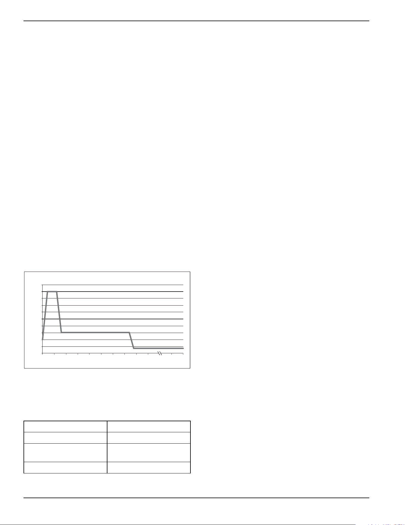
Figure 3-10
illustrates an engine speed profile during a
typical exercise cycle.
Table 3-1
details exercise
information and programming options for all home standby
generators.
Figure 3-10. Low Speed Exercise Profile
NOTE: If Quiet Test is disabled, the generator will
exercise at the rated rpm.
Battery Charger
IMPORTANT NOTE: Contact an IASD if the controller
screen displays “CHARGER MISSING AC.”
NOTE: The battery charger is integrated into the control
module in all models.
The battery charger operates as a smart charger which verifies
:
• output is continually optimized to promote
maximum battery life.
• charging levels are safe.
NOTE: A warning is displayed on the LCD when the
battery needs service.
NOTE: Do not use external battery chargers.
Table 3-1. Generator Exercise Characteristics
Generator Size 9–22 kW
Low Speed Exercise 1950 rpm
Exercise Frequency
Options
Weekly/Bi-Weekly/Monthly
Exercise Time Length 5 minutes
2600
2800
3000
3200
3400
3600
3800
Low Speed Exercise Profile—9–22 kW Generators
1800
2000
2200
2400
0 sec 5 s 10 s 15 s 20 s 25 s 30 s 35 s 40 s 45 s 1 min 5 min
Exercise Speed (RPM)
Exercise Time
004448
Operation
Owner’s Manual for 60 Hz Air-Cooled Generators 21
Manual Transfer Operation
Prior to automatic operation, manually exercise the
transfer switch to verify there is no interference with
proper operation of the mechanism. Manual operation of
the transfer switch is required if electronic operation
should fail.
Transfer to Generator Power Source
1. Verify generator is OFF.
2. Set main line circuit breaker (MLCB) (generator
disconnect) to OFF (OPEN).
3. Turn OFF utility power supply to the transfer switch
using the means provided (such as a main line
utility breaker).
4. See
Figure 3-11. Use the manual transfer handle
(A) inside the transfer switch to move the main
contacts to STANDBY (loads connected to the
standby power source).
5. Press control panel MANUAL mode button to crank
and start the engine.
6. Allow engine to stabilize and warm up for a few
minutes.
7. Set MLCB (generator disconnect) to ON
(CLOSED). The standby power source now
powers the loads.
Figure 3-11. Typical Manual Transfer Switch
Operation
(000132)
DANGER
Electrocution. Do not manually transfer under load.
Disconnect transfer switch from all power sources
prior to manual transfer. Failure to do so will result
in death or serious injury, and equipment damage.
002565
A
MANUAL
• Will not transfer to generator if utility is present.
• Will transfer to generator if utility drops (below 65% of nominal for five consecutive seconds;
dealer programmable) after warm-up.
• Will transfer back when utility returns for 15 consecutive seconds (dealer programmable).
The engine will continue to run until removed from MANUAL mode.
AUTO
• Will start and run if utility drops for five consecutive seconds (dealer programmable).
• Will start an engine warm-up timer (duration varies when
Cold Smart Start is enabled).
–Will not transfer if utility subsequently returns.
–Will transfer to generator if utility is not present.
• Will transfer to utility once utility returns (above 80% of nominal) for 15 consecutive seconds
(dealer programmable).
• Will not transfer to utility unless utility returns. The generator will shut down if the OFF mode
button is pressed or a shutdown alarm is present.
• Once utility power is returned, the generator will shut down after one minute cool-down time.
EXERCISE
• Will not exercise if generator is already running in either AUTO or MANUAL mode.
• During exercise, the controller will only transfer if utility drops during exercise for five seconds
(dealer programmable), and will switch to AUTO.

Operation
22 Owner’s Manual for 60 Hz Air-Cooled Generators
Transfer to Utility Power Source
Shut down generator and transfer to utility source after
utility power has been restored. Proceed as follows to
manually transfer to utility power and shut down the
generator:
1. Set the MLCB (generator disconnect) to OFF
(OPEN).
2. Run engine for one minute at no-load to stabilize
the internal temperature.
3. Press the OFF mode button on the control panel.
The engine will shut down.
4. Verify utility power supply to the transfer switch is
turned OFF.
5. Move the main contacts to the UTILITY position
(loads connected to the utility power source) using
the manual transfer handle (A in
Figure 3-11)
inside the transfer switch.
6. Turn on the utility power supply to the transfer
switch using the means provided.
7. Press the AUTO mode button on the control panel.
8. Return the MLCB (generator disconnect) to ON
(CLOSED).
9. Close and lock the lid.
Automatic Transfer Operation
Proceed as follows to select automatic operation:
1. Verify transfer switch main contacts are set to
UTILITY (loads connected to the utility power
source).
2. Verify normal utility power source voltage is
available to loads connected to the transfer switch.
3. Press the AUTO mode button on the generator
control panel.
4. Set MLCB (generator disconnect) to ON
(CLOSED).
The generator will start automatically when utility source
voltage drops below a preset level. Loads are transferred
to standby power source after the unit starts.
Automatic Sequence of
Operation
Utility Failure
If the generator is set to AUTO, when utility fails (below
65% of nominal) a five second (dealer programmable)
line interrupt delay time is started. The engine cranks and
starts if utility power is still unavailable when the timer
expires. An engine warm-up timer will be initiated once
the engine is started. Timer duration varies depending on
whether or not
Cold Smart Start is enabled. The
controller will transfer the load to the generator when the
warm-up time expires. If the utility power is restored
(above 80% nominal) at any time from the initiation of the
engine start until the generator is ready to accept load
(warm-up time has not elapsed), the controller completes
the start cycle and runs the generator through its normal
cool down cycle. However, the load will remain on the
utility source.
Cranking
The system will control the cyclic cranking as follows:
• 9 kW Unit: five cranking cycles as follows: 15
seconds cranking, 7 seconds resting, followed by
four additional cycles of 7 seconds cranking
followed by 7 seconds resting.
• 11–22 kW Units: five cranking cycles as follows:
16 seconds cranking, 7 seconds resting, 16
seconds cranking, 7 seconds resting, followed by
three additional cycles of 7 seconds cranking
followed by 7 seconds resting.
NOTE: An alarm will be triggered if the generator does
not start after these five attempts.
Operation
Owner’s Manual for 60 Hz Air-Cooled Generators 23
Cold Smart Start
The generator will monitor ambient temperature when
Cold Smart Start is enabled. The warm-up delay will be
adjusted based on prevailing conditions. Cold Smart Start
is enabled at the factory, but can be disabled in the EDIT
menu.
See
Table 3-2. If the ambient temperature is below a
fixed temperature (based on model) upon startup in
AUTO mode, the generator will warm up for 30 seconds.
This allows the engine to warm before a load is applied.
The generator will startup with the normal warm-up delay
of five seconds if the ambient temperature is at or above
the fixed temperature.
A check for proper output voltage buildup will be
performed when the generator engine is started.
If some condition impedes normal voltage creation, such
as frost crystals or dust/dirt preventing a good electrical
connection, the start sequence will be interrupted so a
cleaning cycle of the internal electrical connections can
be attempted.
The cleaning cycle is an extended warming up period
which lasts for several minutes while the normal
generator voltage output is determined to be low. During
this cycle, the generator controller will display “Warming
Up” on the display screen.
The generator controller display will show “Under
Voltage” if the cleaning cycle fails to clear the obstruction.
After several minutes, the alarm message can be
cleared, and the generator restarted.
If the problem persists, make no further attempts to start.
Contact an IASD.
Load Transfer
The transfer of load when the generator is running is
dependent upon the operating mode.
Shutting Generator Down While
Under Load Or During A Utility
Outage
IMPORTANT NOTE: To avoid equipment damage, follow
these steps, in order, during utility outages. Shutdowns
may be required during utility outages to perform routine
maintenance or to conserve fuel.
To turn the generator OFF:
1. Set the main utility disconnect to OFF (OPEN).
2. Set the generator MLCB (generator disconnect) to
OFF (OPEN).
3. Allow the generator to run for a cool-down period of
approximately one minute.
4. At the controller, set the generator to OFF.
5. Remove the 7.5A fuse from the controller.
To turn the generator back ON:
1. Install 7.5A fuse in controller.
2. Confirm the generator MLCB (generator
disconnect) is OFF (OPEN).
3. At the controller, set the generator to AUTO mode.
4. Generator will start and run. Allow generator to run
and warm up for a few minutes.
5. Set the MLCB (generator disconnect) to ON
(CLOSED).
6. Set the main utility disconnect to ON (CLOSED).
The system now operates in automatic mode.
Table 3-2. Cold Smart Start Set Points
Generator Size 9 kW–20 kW 22 kW
Fixed Temperature 50 °F (10 °C) 20 °F (-7 °C)
Automatic start-up. Disconnect utility power and
render unit inoperable before working on unit.
Failure to do so will result in death or serious injury.
(000191)
DANGER

Operation
24 Owner’s Manual for 60 Hz Air-Cooled Generators
This page intentionally left blank.
Maintenance
Owner’s Manual for 60 Hz Air-Cooled Generators 25
Section 4: Maintenance
Maintenance
Regular maintenance will improve performance and
extend engine/equipment life. Generac Power Systems,
Inc. recommends that all maintenance work be
performed by an Independent Authorized Service Dealer
(IASD). Regular maintenance, replacement, or repair of
the emissions control devices and systems may be
performed by any repair shop or person of the owner’s
choosing. To obtain emissions control warranty service
free of charge, the work must be performed by an IASD.
See the emissions warranty.
Preparing for Maintenance
1. Set main utility disconnect to OFF (OPEN).
2. Lift lid and set MLCB (generator disconnect) on
generator to OFF (OPEN).
3. Allow generator to run and cool down for one
minute with no load (if running during a utility
outage).
4. Press OFF mode button on controller.
5. Remove 7.5 A fuse from control panel.
6. Remove front panel and intake side panel.
Performing Scheduled
Maintenance
It is important to perform maintenance as specified in the
Service Schedule for proper generator operation.
Engine oil and oil filter must be changed, and valve
clearance adjusted after the first 25 hours of operation.
Emissions-critical maintenance must be performed as
scheduled in order for the emissions warranty to be valid.
Emissions-critical maintenance consists of servicing the
air filter and spark plug(s) in accordance with the
Service
Schedule
.
The controller will prompt for Schedule A or Schedule B
maintenance to be performed. Schedule A maintenance
consists of the oil, oil filter, and battery check. Schedule B
maintenance includes the oil, oil filter, battery check, air
cleaner, spark plug(s), and valve clearance.
Since most maintenance alerts occur at the same time
(most have two year intervals), only one will appear on
the control panel display at a time. Once the first alert is
cleared, the next active alert will be displayed.
(000182a)
WARNING
Equipment damage. Only qualified service personnel may
install, operate, and maintain this equipment. Failure to follow
proper installation requirements could result in death, serious
injury, and equipment or property damage.
Automatic start-up. Disconnect utility power and
render unit inoperable before working on unit.
Failure to do so will result in death or serious injury.
(000191)
DANGER
Maintenance
26 Owner’s Manual for 60 Hz Air-Cooled Generators
Service Schedule
NOTE: Contact an IASD or visit www.generac.com for additional information on replacement parts.
Maintenance Log
Battery Inspection and Charge Check
Dates Performed:
Oil, Oil Filter, Air Filter, and Spark Plug Replacement
Dates Performed:
Valve Adjustment
Dates Performed:
Service
Daily If Running Continuously
or Before Each Use
Every
Year
Schedule A
Every Two Years
or 200 Hours
Schedule B
Every Four Years
or 400 Hours
Inspect enclosure louvers for dirt and debris *
●
Inspect lines and connections for fuel or oil leaks
●
Inspect engine oil level
●
Check for water intrusion **
●
Perform fuel system leak test
●
Check battery condition, electrolyte level, and state
of charge
●● ●
Replace engine oil and oil filter †
●●
Replace engine air filter
●
Clean; inspect spark plug gap; replace if necessary
●
Inspect/adjust valve clearance ‡
●
Inspect/clean sediment trap Consult local codes and guidelines.
Contact the nearest IASD for assistance if necessary.
* Remove any shrubs or tall grasses which have grown within 3 ft (0.91 m) of intake and discharge louvers on enclosure sides. Clean any debris (dirt, grass
clippings, etc.) which may have accumulated inside the enclosure.
** Verify all sources of potential water intrusion such as water sprinklers, roof run-off, rain gutter downspouts, and sump pump discharges are directed away from
generator enclosure.
† Change engine oil and filter after the first 25 hours of operation. In cold weather conditions (ambient below 40 °F [4.4 °C]), or if unit is operated continuously in hot
weather conditions (ambient above 85 °F [29.4 °C]), change engine oil and filter every year or 100 hours of operation.
‡ Check/adjust valve clearance after the first 25 hours of operation.
Maintenance
Owner’s Manual for 60 Hz Air-Cooled Generators 27
Checking Engine Oil Level
IMPORTANT NOTE: Check oil level daily when power
outages necessitate running the generator for
extended periods.
Proceed as follows to check engine oil level:
1. Set main utility disconnect to OFF (OPEN).
2. Set main line circuit breaker (MLCB) (generator
disconnect) on generator to OFF (OPEN).
3. Run generator for a cool-down period of
approximately one minute.
4. Press OFF mode button to turn generator off. Wait
five minutes.
5. Remove oil dipstick and wipe it dry with a clean
cloth.
6. Completely insert oil dipstick into oil dipstick tube
and remove it.
7. Observe oil level. The level should be at the
“FULL” mark on oil dipstick.
8. If necessary, remove oil fill cap and add oil to
engine (with oil dipstick removed) until level
reaches “FULL” mark. Insert oil dipstick and install
fill cap.
To restart the generator:
1. Press the control panel AUTO mode button.
2. Allow the generator to start and warm up for a few
minutes.
3. Set the generator disconnect on the generator to
ON (CLOSED).
4. The system is now operating in automatic mode.
The main utility disconnect can be turned ON
(CLOSED).
Engine Oil Requirements
T
o maintain the product warranty, the engine oil should be
serviced in accordance with the recommendations of this
manual. For your convenience, Generac Maintenance Kits
are available consisting of engine oil, oil filter, air filter,
spark plug(s), a shop towel, and a funnel. These kits can
be obtained from an IASD.
All Generac oil kits meet minimum American Petroleum
Institute (API) Service Class SJ, SL, or better. Do not use
special additives.
Required Oil
Synthetic SAE 5W-30 for all temperature ranges. See
Engine in General Information.
(000139)
WARNING
Risk of burns. Allow engine to cool before
draining oil or coolant. Failure to do so could
result in death or serious injury.
(000210)
WARNING
Skin irritation. Avoid prolonged or repeated contact with
used motor oil. Used motor oil has been shown to cause
skin cancer in laboratory animals. Thoroughly wash
exposed areas with soap and water.
(000135)
CAUTION
Engine damage. Verify proper type and quantity of
engine oil prior to starting engine. Failure to do so
could result in engine damage.
(000135)
CAUTION
Engine damage. Verify proper type and quantity of
engine oil prior to starting engine. Failure to do so
could result in engine damage.
Maintenance
28 Owner’s Manual for 60 Hz Air-Cooled Generators
Changing the Oil and Oil Filter
Proceed as follows to change the oil and oil filter:
1.
Lift the lid and press the MANUAL mode button on
the control panel to start the engine, and run it until it
is thoroughly warmed up. Press the OFF mode
button on the control panel to shut down the engine.
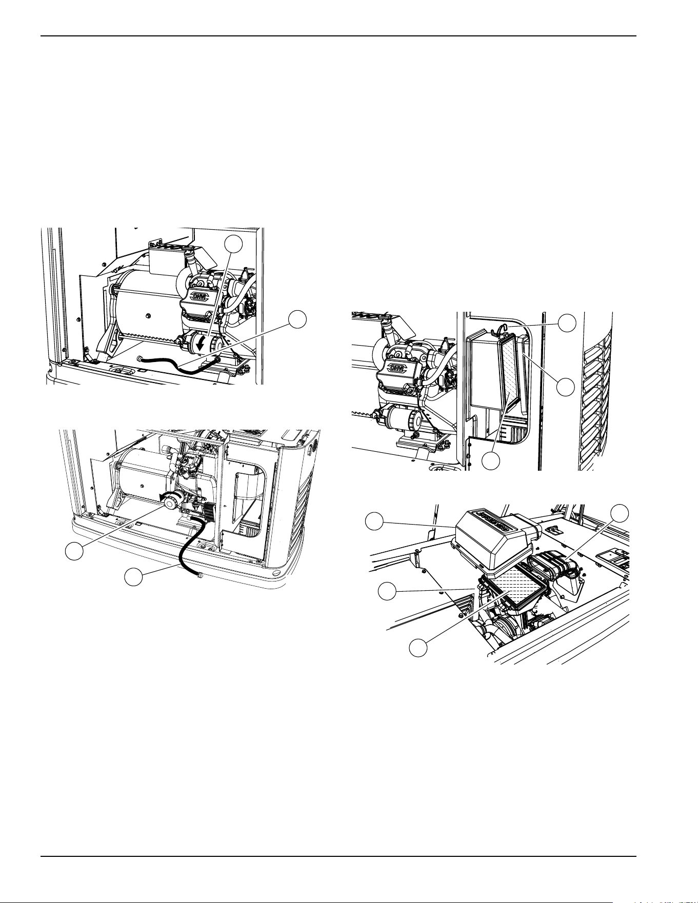
2. See Figure 4-1 or Figure 4-2. A few minutes after
the engine stops, and when it has cooled slightly,
remove the front panel. Pull the oil drain hose (A)
free of its retaining clip. Remove the cap from the
hose and drain the oil into a suitable container.
Figure 4-1. Oil Filter and Drain Location (9 kW)
Figure 4-2. Oil Filter and Drain Location (11-22 kW)
3. Install the cap on the hose. Position and secure the
hose with the retaining clip.
4. Remove oil filter (B) by turning it counterclockwise.
5. Apply a light coating of clean engine oil to the
gasket of the new filter.
6. Screw the new filter on by hand until its gasket
lightly contacts the oil filter adapter. Tighten the
filter an additional three-quarter to one full turn.
7. Fill the engine with the proper recommended oil.
See
Engine Oil Requirements.
8. Press the MANUAL mode button on the control
panel to start the engine. Run for one minute, and
check for leaks.
9. Press the OFF mode button on the control panel to
stop the engine. Wait five minutes.
10. Inspect the oil level. Add oil as needed. DO NOT
OVERFILL.
11. Insert oil dipstick and/or attach fill cap.
12. Press AUTO mode button on the control panel to
return the unit to AUTO mode.
13. Close and lock the lid.
14. Dispose of the used oil and filter at a proper
collection center.
Servicing the Air Cleaner
Proceed as follows to service the air cleaner:
1.
Lift the lid and press the OFF mode button on the
control panel to stop the generator. Remove the front
pane
l.
2. See Figure 4-3 or Figure 4-4. Remove the cover
clips (A) and air cleaner cover (B).
.
Figure 4-3. Servicing Air Cleaner (9 kW)
Figure 4-4. Servicing Air Cleaner (11-22 kW)
3. Remove the old air filter element (C) and discard.
4. Thoroughly clean the air cleaner enclosure of any
dust or debris.
5. Install a new air filter element.
6.
Install the air cleaner cover and fasten the cover clips.
7. (11-22 kW units only): Verify air inlet duct (D) is
properly connected to the air cleaner cover.
8. Press the AUTO mode button on the control panel
to return the unit to AUTO mode.
001831
B
A
001799
B
A
A
B
C
001820
001814
B
A
C
D
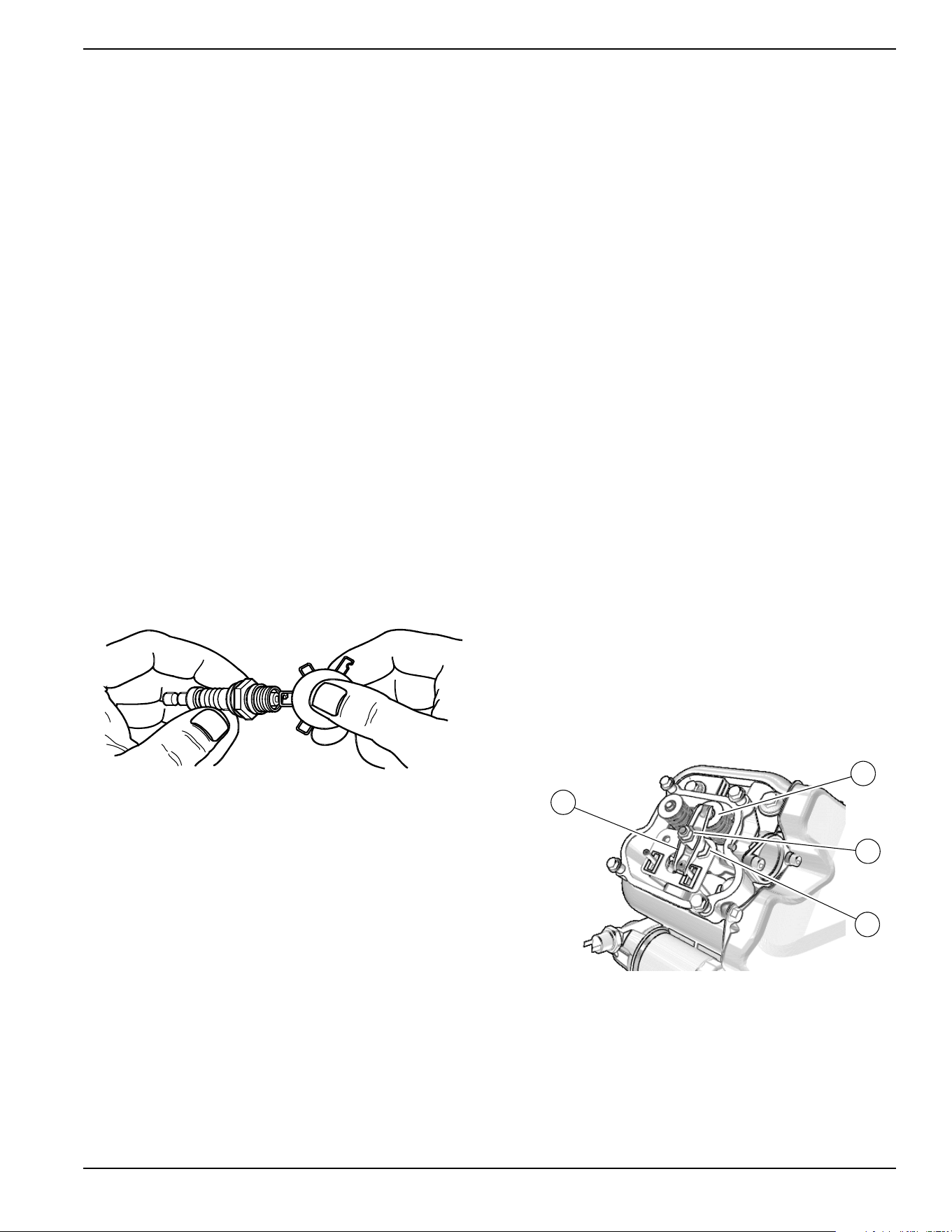
Maintenance
Owner’s Manual for 60 Hz Air-Cooled Generators 29
Spark Plug(s)
Proceed as follows to inspect spark plug gap(s) and
replace spark plug(s) as necessary:
1. With the generator OFF and the engine cool, lift the
lid and remove the front panel.
2. Clean the area around the base of the spark
plug(s) to keep dirt and debris out of the engine.
3. Remove spark plug(s) and inspect the condition.
Install new plug(s) if existing plug(s) is worn or if
reuse is questionable.
4. Clean plug(s) by scraping or washing with a wire
brush and commercial solvent. Do not blast plug(s)
to clean.
NOTE: Clean spark plug in emergency situations only.
Otherwise, replace spark plug.
5. Inspect spark plug gap using a wire feeler gauge.
See
Figure 4-5. Replace spark plug if gap is out of
specification. See General Information.
NOTE: New spark plugs should have the gap checked
prior to installation.
6. Install the spark plug(s), and torque to 18.4 ft-lbs
(25 Nm).
7. Press the control panel AUTO button to return the
unit to AUTO mode.
Figure 4-5. Spark Plug Gap Measurement
Valve Clearance Adjustment
IMPORTANT NOTE: Contact an IASD for service
assistance. Proper valve clearance is essential for
prolonging the life of the engine.
Check valve clearance after the first 25 hours of
operation, then after 400 hour intervals. Adjust if
necessary.
Check Valve Clearance
NOTE: The engine should be cool before checking valve
clearance. Adjustment is not needed if valve clearance is
within the dimensions provided in
Engine.
1. Close fuel valve and disconnect battery to avoid
accidental start-up.
2. Remove spark plug wire(s), and position wire(s)
away from plug(s).
3. Remove spark plug(s).
4. Remove the four screws attaching the valve cover.
Remove and discard the gasket. (Repeat for
second cylinder, if equipped.)
5. Verify piston is at top dead center (TDC) of its
compression stroke (both valves closed). To move
the piston to TDC, remove the intake baffle at the
front of the engine to access the flywheel nut. Use
a large socket and socket wrench to rotate the
flywheel nut clockwise, which will rotate the
crankshaft. Watch the piston through the spark
plug hole. The piston should move up and down.
The piston is at TDC when it is at its highest point
of travel.
6. See
Figure 4-6 or Figure 4-7. Check the valve
clearance between each rocker arm (E) and valve
stem (F) with a feeler gauge.
.
Figure 4-6. Valve Clearance Adjustment (9 kW)
000211
001812
C
D
F
E
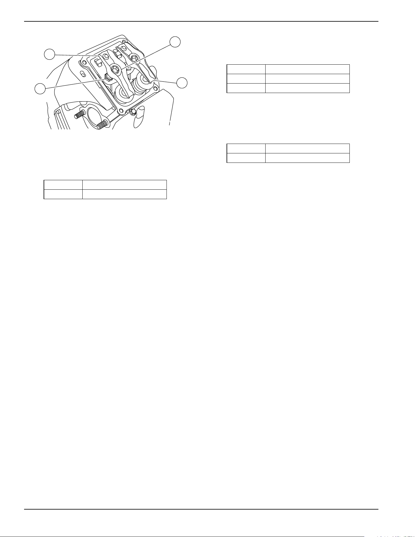
Maintenance
30 Owner’s Manual for 60 Hz Air-Cooled Generators
Figure 4-7. Valve Clearance Adjustment (11-22 kW)
7. Install replacement valve cover gasket(s).
8. Install valve cover(s). Tighten fasteners in a cross
pattern, torquing to:
Adjust Valve Clearance
See
Figure 4-6 or Figure 4-7. Proceed as follows to
adjust valve clearance:
NOTE: Allow engine to cool before adjusting valve
clearance.
1. Remove spark plug wire(s) and position wire(s)
away from plugs.
2. Remove spark plug(s).
3. Remove four screws attaching valve cover.
Remove and discard gasket.
4. Verify piston is at top dead center (TDC) of its
compression stroke (both valves closed).
5. Loosen rocker jam nut (C) using a 10 mm wrench
(9-11 kW units) or 13 mm wrench (16-22 kW units.)
6. Turn pivot ball stud (D) using a 14 mm wrench (9
kW units), 8 mm wrench (11 kW units), or 10 mm
hex key (16-22 kW units) while checking clearance
between rocker arm (E) and valve stem (F) with a
feeler gauge. Adjust clearance as per
Engine.
NOTE: Hold the rocker jam nut in place as the pivot ball
stud is turned.
7. When valve clearance is correct, hold pivot ball
stud (D) in place with a wrench and tighten rocker
arm jam nut. Tighten jam nut according to the
following torque specifications:
8. After tightening jam nut, inspect valve clearance to
verify it did not change.
9. Install new valve cover gasket.
10. Install the valve cover. Tighten fasteners in a cross
pattern, torquing to:
NOTE: Start all four screws before tightening, or it will
not be possible to get all the screws in place. Verify the
valve cover gasket is in place.
11. Install spark plugs and tighten to 18 ft-lbs (25 Nm).
12. Attach the spark plug wire to the spark plug.
13. Repeat the process for the other cylinder if
equipped.
9 kW 80 in-lb (9.0 Nm)
11–22kW 60 in-lb (6.8 Nm)
002380
F
C
E
D
9 kW 53 in-lb (6.0 Nm)
11 kW 72 in-lb (8.2 Nm)
16–22kW 174 in-lb (19.68 Nm)
9 kW 80 in-lb (9.0 Nm)
11–22kW 60 in-lb (6.8 Nm)
Maintenance
Owner’s Manual for 60 Hz Air-Cooled Generators 31
Battery Maintenance
Always recycle batteries in accordance with local laws
and regulations. Contact your local solid waste collection
site or recycling facility to obtain information on local
recycling processes. For more information on battery
recycling, visit the Battery Council International website
at:
http://batterycouncil.org
Strictly observe the following precautions when working
on batteries:
• Remove the 7.5 A fuse from the generator control
panel.
• Disconnect the battery charger as directed in
Battery Maintenance.
• Use tools with insulated handles.
• Wear rubber gloves and boots.
• Do not place tools or metallic objects on top of the
battery.
• Disconnect the charging source prior to connecting
or disconnecting battery terminals.
• Wear full eye protection and protective clothing.
•
If electrolyte contacts the skin, wash it off immediately
with water
.
• If electrolyte contacts the eyes, immediately
thoroughly flush with water and seek medical
attention.
• Wash down spilled electrolyte with an acid
neutralizing agent. A common practice is to use a
solution of 1 lb (454 g) bicarbonate of soda to 1 gal
(3.8 L) of water. Add bicarbonate of soda solution
until the evidence of reaction (foaming) has
ceased. Flush the resulting liquid with water and
dry the area completely.
• DO NOT smoke near the battery.
• DO NOT cause flame or spark in the battery area.
• Discharge static electricity from the body before
touching the battery by first touching a grounded
metal surface.
The battery should be regularly inspected per the
Service Schedule. Contact an IASD for assistance if
necessary.
Proceed as follows to inspect the battery:
1. Press the OFF mode button to shut down the
generator, then lift the lid and remove the front
panel.
2. Remove the 7.5 A fuse from the control panel.
3. Remove the intake side panel. (See
Intake Side
Panel Removal.)
4. See Figure 4-8. Inspect battery posts and cables
for tightness and corrosion. Tighten and clean as
necessary.
(000188)
DANGER
Electrocution. Do not wear jewelry while
working on this equipment. Doing so will
result in death or serious injury.
(000162)
WARNING
Explosion. Do not dispose of batteries in a fire. Batteries
are explosive. Electrolyte solution can cause burns and
blindness. If electrolyte contacts skin or eyes, flush with water
and seek immediate medical attention.
(000137a)
WARNING
Explosion. Batteries emit explosive gases while charging.
Keep fire and spark away. Wear protective gear when
working with batteries. Failure to do so could result in
death or serious injury.
(000164)
WARNING
Electrical shock. Disconnect battery ground
terminal before working on battery or battery
wires. Failure to do so could result in death
or serious injury.
(000138a)
WARNING
(000163a)
WARNING
Risk of burn. Do not open or mutilate batteries.
Batteries contain electrolyte solution which can
cause burns and blindness. If electrolyte contacts
skin or eyes, flush with water and seek immediate
medical attention.
WARNING
Environmental Hazard. Always recycle batteries at an
official recycling center in accordance with all local
laws and regulations. Failure to do so could result in
environmental damage, death or serious injury.
(000228)
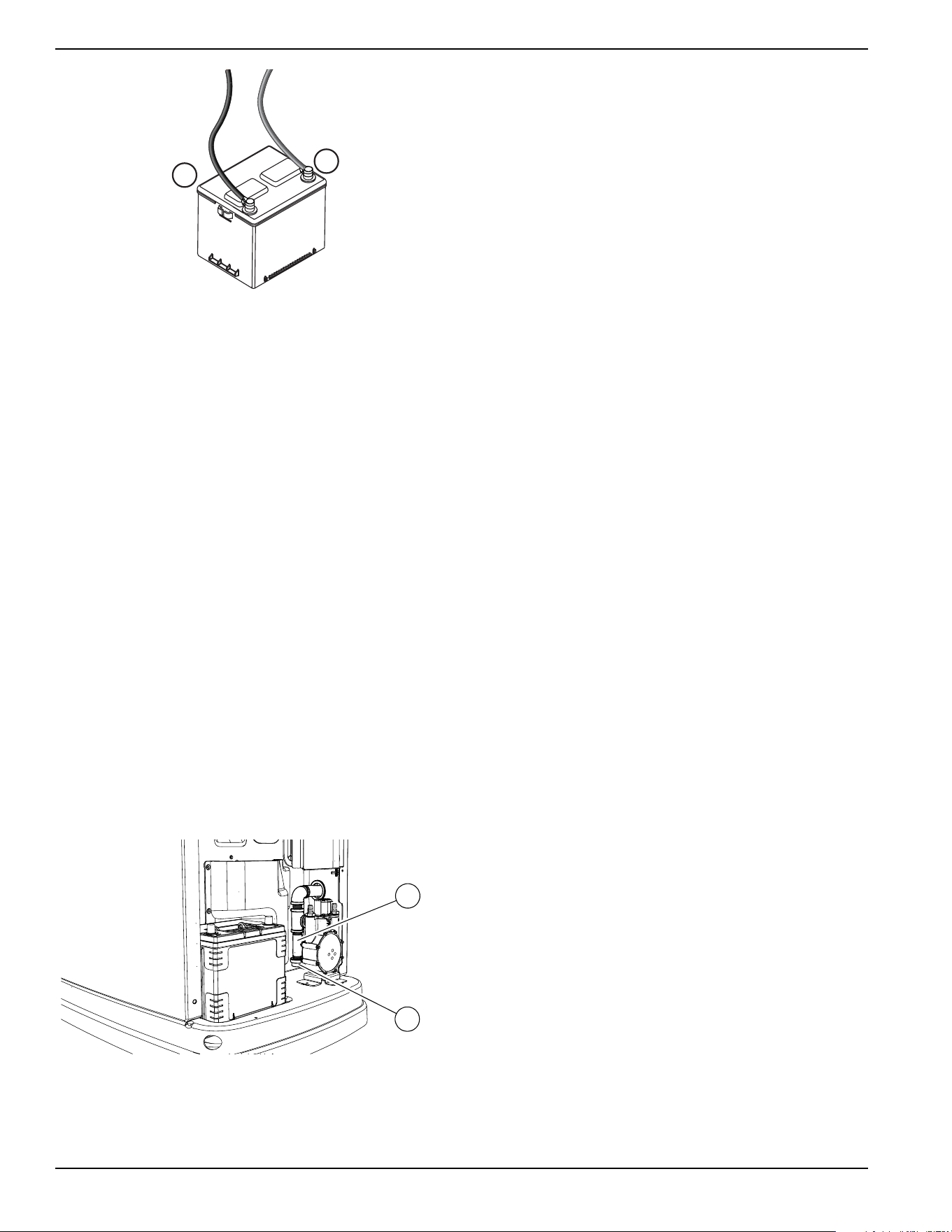
Maintenance
32 Owner’s Manual for 60 Hz Air-Cooled Generators
Figure 4-8. Battery Cables
5. Unsealed batteries only: Completely disconnect
the battery. Check the battery fluid level and, if
necessary, fill with distilled water only. DO NOT
use tap water. Also, have an IASD or a qualified
service technician check the state of charge and
condition.
6. When inspection is complete, connect the battery
cables, install the intake side panel, and install the
7.5 A fuse.
7.
Place the generator in auto by pressing the AUTO
mode button on the controller.
8.
Install front panel and close generator lid.
Cleaning the Sediment Trap
The sediment trap removes contaminants (moisture and
fine particles) from gaseous fuels before they enter the
fuel regulator. Accumulated moisture and particles must
be emptied from the sediment trap per local codes and
guidelines.
Proceed as follows to clean the sediment trap:
1. Remove intake side panel (see
Intake Side Panel
Removal).
2. Turn the generator fuel supply OFF.
3.
See
Figure 4-9
. Unscrew and remove cap (A).
Figure 4-9. Cleaning the Sediment Trap
4. Use a clean-out tool (not provided) to remove
accumulated moisture and particles from cap and
body (B).
5. Wipe the inside of each component with a clean,
dry, lint-free cloth.
6. Seal the threads of the cap with appropriate
sealing compound. Install the cap and hand-
tighten.
7. Tighten the cap with an appropriately sized pipe
wrench. DO NOT overtighten.
8. Turn the generator fuel supply on. Check for leaks
by spraying all connection points with a non-
corrosive gas leak detection fluid. The solution
should not be blown away or form bubbles.
9. Install the intake side panel.
Post Maintenance Checks
1. Perform required maintenance procedure(s).
2. Install the intake side panel and front panel if
removed. (See
Intake Side Panel Removal and
Removing the Front Access Panel.)
3. Install the 7.5 A fuse in the control panel.
4. Complete the Installation Wizard information.
5. Press the AUTO mode button on the control panel.
Allow the unit to run for one minute with no load (if
running during a utility outage).
6. Set the MLCB (generator disconnect) on the
generator to ON (CLOSED).
7. Turn the main utility disconnect ON (CLOSED).
The system is now in automatic mode.
NOTE: If proper utility is present at this time, the
generator will perform its usual shutdown process.
–
+
001832
001821
A
B
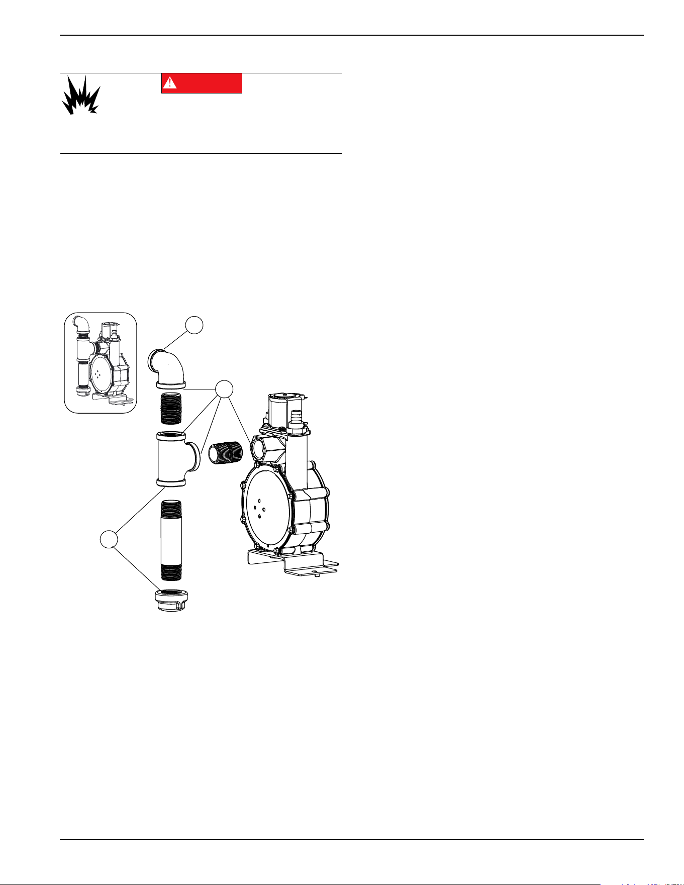
Maintenance
Owner’s Manual for 60 Hz Air-Cooled Generators 33
Perform Leak Test
All products are tested at the factory before shipping to
ensure the performance and integrity of the fuel system.
However, it is important to perform a final fuel system
leak test before starting the generator. The entire fuel
system should be tested from supply to regulator.
See
Figure 4-10. Perform a final fuel system leak test
after generator installation. The test will identify possible
leaks at all connection points (A).
It is best practice to perform a fuel system leak test
during normally-scheduled maintenance.
Figure 4-10. Connection Points to Leak Check
Check for leaks by spraying all connection points with a
non-corrosive gas leak detection fluid. The solution
should not be blown away or form bubbles.
Attention After Submersion
DO NOT start or operate the generator if it has been
submerged in water. Have an IASD thoroughly clean, dry,
and inspect the generator following any submersion in
water. If the structure (home) has been flooded, it should
be inspected by a certified electrician to verify there will
not be any electrical problems during generator operation
or when utility power is returned.
Corrosion Protection
Regular scheduled maintenance should be conducted to
perform a visual inspection of the unit for corrosion. Inspect
all metal components of the generator, including the base
frame, brackets, alternator can, the entire fuel system
(inside and outside of the generator), and fastener
locations. If there is corrosion found on generator
components (e.g. regulator, engine/alternator mounts, fuel
plenum, etc.), replace parts as necessary.
Periodically wash and wax the enclosure using automotive
type products. Do not spray the unit with a hose or power
washer. Use warm, soapy water and a soft cloth. Frequent
washing is recommended in salt water/coastal areas.
Spray engine linkages with a light oil such as WD-40.
(000192)
DANGER
Explosion and fire. Fuel and vapors are extremely
flammable and explosive. No leakage of fuel is
permitted. Keep fire and spark away. Failure to do
so will result in death or serious injury.
A
A
A
004038
Maintenance
34 Owner’s Manual for 60 Hz Air-Cooled Generators
Remove From, and Return To
Service Procedure
Remove From Service
If the generator cannot be exercised monthly, at a
minimum, and will be out of service longer than 90 days,
proceed as follows to prepare the generator for storage:
1. Start engine and allow it to warm up.
2. Close fuel shutoff valve in the fuel supply line and
allow engine to stop.
3. Once the engine has stopped, set the generator
MLCB (generator disconnect) to OFF (OPEN).
4. Disconnect battery charger AC input T1/Neutral
cable (with white sleeve) at controller.
5. Remove 7.5 A fuse from the generator control
panel.
6. Disconnect battery cables. Remove the negative
cable first.
7. Drain oil completely while the engine is still warm,
and then fill crankcase with oil. See
Engine Oil
Requirements
.
8. Attach a tag to the engine indicating the viscosity
and classification of the new oil in the crankcase.
9. Remove spark plug(s) and spray a fogging agent
into spark plug(s) threaded openings. Install and
tighten spark plug(s) to specification.
10. Remove battery and store in a cool, dry place.
11. Clean and wipe down the generator enclosure.
Return to Service
Proceed as follows to return the unit to service after
storage:
1. Check the tag on the engine for oil viscosity and
classification. Drain and fill with proper oil, if
necessary.
2. Check the state of the battery. Fill all cells of
unsealed batteries to the proper level with distilled
water. DO NOT use tap water. Recharge the
battery to 100% state of charge. Replace the
battery if defective.
3. Clean and wipe down the generator enclosure.
4. Verify 7.5 A fuse is removed from generator control
panel.
5. Connect battery. Observe battery polarity. Damage
may occur if the battery is connected incorrectly.
Install positive cable first.
6. Connect battery charger AC input T1/Neutral cable
(with white sleeve) at controller.
7. Open the fuel shutoff valve.
8. Insert 7.5 A fuse into the generator control panel.
9. Complete the Installation Wizard procedure
(diagrammed in the generator installation manual).
10. Press the MANUAL mode button to start the unit.
Allow the unit to warm up for a few minutes.
11. Press the control panel OFF mode button to stop
the unit.
12. Set the MLCB (generator disconnect) to ON
(CLOSED).
13. Press the AUTO mode button on the control panel.
The generator is ready for service.
NOTE: The exercise timer and current date and time
must be reset if a battery has been completely
discharged or disconnected.
WARNING
Explosion. Batteries emit explosive gases.
Always disconnect negative battery cable
first to avoid spark. Failure to do so could
result in death or serious injury.
(000238)
(000133)
WARNING
Explosion. Batteries emit explosive gases.
Always connect positive battery cable first to
avoid spark. Failure to do so could result in
death or serious injury.
Troubleshooting / Quick Reference Guide
Owner’s Manual for 60 Hz Air-Cooled Generators 35
Section 5: Troubleshooting / Quick Reference Guide
Generator Troubleshooting
Problem Cause Correction
Engine will not
crank.
Blown fuse.
Correct short circuit condition by replacing 7.5 A
fuse in generator control panel. Contact an
Independent Authorized Service Dealer (IASD) if
fuse continues to blow.
Loose, corroded, or defective battery cables. Tighten, clean, or replace as necessary.*
Defective starter contact. Tighten, clean, or replace as necessary.*
Defective starter motor. Tighten, clean, or replace as necessary.*
Discharged battery. Charge or replace battery.
Engine cranks but
will not start.
No fuel. Replenish fuel / turn on fuel valve.
Defective fuel solenoid (FS). Replenish fuel / turn on fuel valve.
Open Wire 14 from controller. Replenish fuel / turn on fuel valve.
Defective spark plug(s). Clean; inspect gap; replace plug(s) if necessary.
Valve clearance out of adjustment. Reset valve clearance
Engine starts hard
and runs rough.
Air cleaner plugged or damaged. Inspect and clean air cleaner.
Defective spark plug(s). Clean; inspect gap; replace plug(s) as needed.
Incorrect fuel pressure.
Confirm fuel pressure to regulator is 10–12 in water
column (19–22 mm Hg) for LP, and 3.5–7.0 in water
column (9–13 mm Hg) for natural gas.
Fuel selector in wrong position. Turn fuel conversion valve to correct position.
Valve(s) out of adjustment. Adjust valve clearance.
Internal engine issue. Contact an IASD for assistance.
Generator is set to
OFF, but the engine
continues to run.
Controller wired incorrectly. Contact an IASD for assistance.
Defective control board. Contact an IASD for assistance.
No AC output from
generator.
Main line circuit breaker (MLCB) (generator
disconnect) is OFF (OPEN).
Reset generator disconnect to ON (CLOSED).
Generator internal failure. Contact an IASD for assistance.
Engine may be warming up.
Refer to
Cold Smart Start
Check the controller screen to verify status.
Troubleshooting / Quick Reference Guide
36 Owner’s Manual for 60 Hz Air-Cooled Generators
No transfer to
standby after utility
source failure.
MLCB (generator disconnect) is OFF (OPEN). Reset generator disconnect to ON (CLOSED).
Defective transfer switch coi Contact an IASD for assistance
Defective transfer relay. Contact an IASD for assistance
Transfer relay circuit open. Contact an IASD for assistance
Defective control logic board. Contact an IASD for assistance
Engine may be warming up.
Refer to
Cold Smart Start.
Check the controller screen to verify status.
Unit consumes
large amounts of oil.
Excessive engine oil. Adjust oil to proper level.
Defective engine breather. Contact an IASD for assistance
Improper type or viscosity of oil
See
Engine Oil Requirements
Damaged gasket, seal, or hose. Check for oil leaks.
Restricted air filter. Replace air filter.
* Contact an IASD for assistance.
Problem Cause Correction
Troubleshooting / Quick Reference Guide
Owner’s Manual for 60 Hz Air-Cooled Generators 37
Quick Reference Guide
To clear an active alarm, press the OFF mode button on the control panel, then the ENTER button, and finally the
AUTO mode button. Contact an IASD if the alarm reoccurs.
Active Alarm LED Problem Things to Check Solution
NONE
FLASHING
GREEN
Unit running in AUTO
but no power in house.
Check MLCB. Check MLCB. If it is ON, contact an IASD.
HIGH
TEMPERATURE
RED
Unit shuts down during
operation.
Check the LEDs /
screen for alarms.
Check ventilation around the generator,
intake, exhaust, and rear of generator. If
no obstructions are present, contact an
IASD.
OVERLOAD
REMOVE LOAD
RED
Unit shuts down during
operation.
Check the LEDs /
screen for alarms.
Clear alarm and remove household loads
from the generator. Put in AUTO and
restart.
RPM SENSE LOSS RED
Unit was running and
shut down, attempts to
restart.
Check the LEDs /
screen for alarms.
Clear alarm and remove household loads
from the generator. Put into AUTO and
restart. If generator does not start, contact
an IASD.
NOT ACTIVATED NONE
Unit will not start in
AUTO with utility loss.
Check if screen says
unit not activated.
Refer to “Activation” in installation
manual.
NONE GREEN
Unit will not start in
AUTO with utility loss.
Check screen for start
delay countdown.
If the startup delay is greater than
expected, contact an IASD to adjust from
2 to 1500 seconds.
LOW OIL
PRESSURE
RED
Unit will not start in
AUTO with utility loss.
Check the LEDs /
screen for alarms.
Check oil level and add oil as needed. If
oil level is correct, contact an IASD.
RPM SENSE LOSS RED
Unit will not start in
AUTO with utility loss.
Check the LEDs /
screen for alarms.
Clear alarm. Using the control panel,
check the battery by navigating to the
BATTERY MENU option from the MAIN
MENU. If battery condition displays
GOOD, contact an IASD. If control panel
displays CHECK BATTERY, replace the
battery.
OVERCRANK RED
Unit will not start in
AUTO with utility loss.
Check the LEDs /
screen for alarms.
Check fuel line shutoff valve is ON. Clear
alarm. Start the unit in MANUAL. If it does
not start, or starts and runs rough, contact
an IASD.
LOW VOLTS
REMOVE LOAD
RED
Unit will not start in
AUTO with utility loss.
Check the LEDs /
screen for alarms.
Clear alarm and remove household loads
from the generator. Put in AUTO and
restart.
OVERSPEED RED
Unit will not start in
AUTO with utility loss.
Check the LEDs /
screen for alarms.
Contact an IASD.
UNDERVOLTAGE RED
Unit will not start in
AUTO with utility loss.
Check the LEDs /
screen for alarms.
Contact an IASD.
UNDERSPEED RED
Unit will not start in
AUTO with utility loss.
Check the LEDs /
screen for alarms.
Contact an IASD.
STEPPER
OVERCURRENT
RED
Unit will not start in
AUTO with utility loss.
Check the LEDs /
screen for alarms.
Contact an IASD.
MISWIRE RED
Unit will not start in
AUTO with utility loss.
Check the LEDs /
screen for alarms.
Contact an IASD.
Troubleshooting / Quick Reference Guide
38 Owner’s Manual for 60 Hz Air-Cooled Generators
OVERVOLTAGE RED
Unit will not start in
AUTO with utility loss.
Check the LEDs /
screen for alarms.
Contact an IASD.
AUXILIARY
SHUTDOWN
RED Unit will not start.
Check auxiliary
shutdown switches
Set auxiliary shutdown switch(es) to
CLOSED (I). Clear alarm.
LOW BATTERY YELLOW
Yellow LED illuminated
in any state.
Check the screen for
additional information.
Clear alarm. Using the control panel,
check the battery by navigating to the
BATTERY MENU option from the MAIN
MENU. If battery condition displays
GOOD, contact an IASD. If control panel
displays CHECK BATTERY, replace the
battery.
BATTERY
PROBLEM
YELLOW
Yellow LED illuminated
in any state.
Check the screen for
additional information.
Contact an IASD.
CHARGER
WARNING
YELLOW
Yellow LED illuminated
in any state.
Check the screen for
additional information.
Contact an IASD.
CHARGER
MISSING AC
YELLOW
Yellow LED illuminated
in any state.
Check the screen for
additional information.
Contact an IASD.
SERVICE A YELLOW
Yellow LED illuminated
in any state.
Check the screen for
additional information.
Perform SERVICE A maintenance. Press
ENTER to clear.
SERVICE B YELLOW
Yellow LED illuminated
in any state.
Check the screen for
additional information.
Perform SERVICE B maintenance. Press
ENTER to clear.
INSPECT
BATTERY
YELLOW
Yellow LED illuminated
in any state.
Check the screen for
additional information.
Inspect battery. Press ENTER to clear.
Active Alarm LED Problem Things to Check Solution


Part No. 10000006551 Rev. C 03/16/18
©2018 Generac Power Systems, Inc.
All rights reserved
Specifications are subject to change without notice.
No reproduction allowed in any form without prior written
consent from Generac Power Systems, Inc.
Generac Power Systems, Inc.
S45 W29290 Hwy. 59
Waukesha, WI 53189
1-888-GENERAC (1-888-436-3722)
www.generac.com
