SAVE THIS MANUAL FOR FUTURE REFERENCE
®
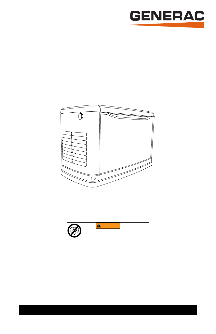
Owner’s Manual
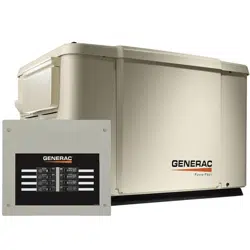
60 Hz Air-Cooled Generators
10 kW to 26 kW
Para español, visita: http://www.generac.com/service-support/product-support-lookup
Pour le français, visiter : http://www.generac.com/service-support/product-support-lookup
Register your Generac product at:
WWW.GENERAC.COM
1-888-GENERAC
(888-436-3722)
(000209b)
WARNING
Loss of life. This product is not intended to
be used in a critical life support application.
Failure to adhere to this warning could result
in death or serious injury.
ii Owner’s Manual for 60 Hz Air-Cooled Generators
Use this page to record important information about this generator.
Record the information found on the unit data
label on this page. See General Information
for the location of the unit data label. The unit
has a label plate affixed to the inside partition,
to the left of the control panel console as
shown in Figure 2-1, Figure 2-2, or Figure 2-
3. See Operation for directions on how to
open the top lid and remove the front panel.
Always supply the complete model and serial
numbers of the unit when contacting an Inde-
pendent Authorized Service Dealer (IASD)
about parts and service.
Operation and Maintenance: Correct main-
tenance and care of the unit ensures a mini-
mum number of problems, and keeps
operating expenses at a minimum. It is the
operator’s responsibility to perform all safety
inspections, to verify all maintenance for safe
operation is performed promptly, and to have
the equipment inspected periodically by an
IASD. Normal maintenance, service, and
replacement of parts are the responsibility of
the owner/operator and are not considered
defects in materials or workmanship within the
terms of the warranty. Individual operating
habits and usage may contribute to the need
for additional maintenance or service.
When the generator requires servicing or
repairs, Generac recommends contacting an
IASD for assistance. Authorized service tech-
nicians are factory-trained and are capable of
handling all service needs. To locate the near-
est IASD, please visit the dealer locator at:
www.generac.com/Dealer-Locator.
Model:
Serial:
Production Date:
Volts:
LPV Amps:
NG Amps:
Hz:
Phase:
Controller P/N:
STA MAC ID:
SSID:
(000393a)
WARNING
CANCER AND REPRODUCTIVE HARM
www.P65Warnings.ca.gov.

Owner’s Manual for 60 Hz Air-Cooled Generators iii
Table of Contents
Section 1: Safety Information
Introduction ..................................... 1
Read This Manual Thoroughly ............1
Safety Rules.................................... 1
How to Obtain Service ........................2
General Hazards............................. 2
Exhaust Hazards............................. 2
Electrical Hazards ........................... 3
Fire Hazards.................................... 3
Explosion Hazards .......................... 3
Battery Hazards .............................. 4
Section 2: General Information
Generator Components and
Control Locations ............................ 5
Data Decals..................................... 8
Specifications .................................. 9
Generator ............................................9
Engine .................................................9
Protection Systems ....................... 10
Emissions...................................... 10
Fuel Requirements........................ 10
Battery Requirements ................... 10
Battery Charger............................. 11
Engine Oil Requirements .............. 11
Activating the Generator ............... 11
Wi-Fi Module................................. 11
Replacement Parts........................ 11
Accessories................................... 11
Section 3: Operation
Site Prep Verification..................... 13
Generator Enclosure ..................... 13
Opening the Lid .................................13
Front Access Panel Removal ............13
Intake Side Panel Removal ...............14
Main Line Circuit Breaker (Generator
Disconnect) .......................................14
LED Indicator Lights ..........................14
Generator Emergency Shutdown
Switch ........................................... 15
Control Panel Interface ................. 15
Using the AUTO/OFF/MANUAL
Buttons.......................................... 15
Operating Modes........................... 16
Interface Menu Displays................ 16
LCD Panel .........................................16
Menu System Navigation .............. 17
Setting the Exercise Timer ............ 19
Battery Charger ............................. 19
Manual Transfer Operation............ 19
Transfer to Generator Power
Source ...............................................19
Transfer to Utility Power Source ........20
Automatic Transfer Operation ....... 20
Automatic Sequence of
Operation....................................... 20
Utility Failure ......................................20
Cranking ............................................20
Cold Smart Start ................................20
Cleaning Cycle ..................................21
Load Transfer ....................................21
Shutting Generator Down While Under
Load or During a Utility Outage ..... 21
Section 4: Maintenance
Maintenance .................................. 22
Preparing for Maintenance ............ 22
Performing Scheduled
Maintenance .................................. 22
Service Schedule........................... 23
Maintenance Log ...................................23
Checking Engine Oil Level ............ 24
Engine Oil Requirements ..................24
Changing the Oil and Oil Filter ...... 24
Servicing the Air Cleaner............... 25
Spark Plug(s)................................. 26
Valve Clearance Adjustment ......... 26
Checking Valve Clearance ................26
Adjusting Valve Clearance ................27
Battery Maintenance...................... 27
Inspecting the Battery ........................28
Cleaning the Sediment Trap.......... 29
Post Maintenance Checks............. 29
Performing Fuel System Leak Test ...29
Attention After Submersion............ 30
Corrosion Protection...................... 30
Remove From and Return To
Service Procedure ......................... 30
Remove From Service .......................30
Return to Service ...............................30
Section 5: Troubleshooting /
Quick Reference Guide
Generator Troubleshooting............ 32
Quick Reference Guide ................. 34
Safety Information
1 Owner’s Manual for 60 Hz Air-Cooled Generators
Section 1: Safety Information
Introduction
Thank you for purchasing this compact, high
performance, air-cooled, engine-driven gen-
erator. It is designed to automatically supply
electrical power to operate critical loads
during a utility power failure.
This unit is factory installed in an all-weather,
metal enclosure intended exclusively for out-
door installation. This generator will operate
using either vapor withdrawn liquid propane
(LP) or natural gas (NG).
NOTE: This generator is suitable for supplying
typical residential loads such as induction
motors (sump pumps, refrigerators, air condi-
tioners, furnaces, etc.), electronic components
(computer, monitor, TV, etc.), lighting loads,
and microwaves, when sized correctly. This
unit is equipped with a Wi-Fi
®
module, which
allows the generator owner to monitor genera-
tor status from anywhere they have Internet
access.
NOTE: Wi-Fi
®
is a registered trademark of Wi-
Fi Alliance
®
.
The information in this manual is accurate
based on products produced at the time of
publication. The manufacturer reserves the
right to make technical updates, corrections,
and product revisions at any time without
notice.
Read This Manual Thoroughly
If any section of this manual is not under-
stood, contact the nearest Independent
Authorized Service Dealer (IASD) or Gen-
erac Customer Service at 1-888-436-3722
(1-888-GENERAC), or visit www.gen-
erac.com for starting, operating, and servic-
ing procedures. The owner is responsible for
correct maintenance and safe use of the unit.
This manual must be used in conjunction with
all other supporting product documentation
supplied with the product.
SAVE THESE INSTRUCTIONS for future ref-
erence. This manual contains important
instructions that must be followed during
placement, operation, and maintenance of
the unit and its components. Always supply
this manual to any individual that will use this
unit, and instruct them on how to correctly
start, operate, and stop the unit in case of
emergency.
Safety Rules
The manufacturer cannot anticipate every
possible circumstance that might involve a
hazard. The alerts in this manual, and on
tags and decals affixed to the unit, are not all
inclusive. If using a procedure, work method,
or operating technique that the manufacturer
does not specifically recommend, verify that
it is safe for others and does not render the
equipment unsafe.
Throughout this publication, and on tags and
decals affixed to the unit, DANGER, WARN-
ING, CAUTION, and NOTE blocks are used
to alert personnel to special instructions
about a particular operation that may be haz-
ardous if performed incorrectly or carelessly.
Observe them carefully. Alert definitions are
as follows:
NOTE: Notes contain additional information
important to a procedure and will be found
within the regular text of this manual.
These safety alerts cannot eliminate the haz-
ards that they indicate. Common sense and
strict compliance with the special instructions
while performing the action or service are
essential to preventing accidents.
(000100a)
Consult Manual. Read and understand manual
completely before using product. Failure to
completely understand manual and product
could result in death or serious injury.
WARNING
(000001)
DANGER
Indicates a hazardous situation which, if not avoided,
will result in death or serious injury.
(000002)
WARNING
Indicates a hazardous situation which, if not avoided,
could result in death or serious injury.
(000003)
CAUTION
Indicates a hazardous situation which, if not avoided,
could result in minor or moderate injury.
Safety Information
Owner’s Manual for 60 Hz Air-Cooled Generators 2
How to Obtain Service
When the unit requires servicing or repairs,
contact Generac Customer Service at 1-888-
GENERAC (1-888-436-3722) or visit
www.generac.com for assistance.
When contacting Generac Customer Service
about parts and service, always supply the
complete model and serial number of the unit
as given on its data decal located on the unit.
Record the model and serial numbers in the
spaces provided on the front cover of this
manual.
General Hazards
• Inspect generator regularly, and contact the
nearest IASD for parts needing repair or
replacement.
Exhaust Hazards
(000190)
DANGER
Loss of life. Property damage. Installation must
always comply with applicable codes, standards, laws
and regulations. Failure to do so will result in death
or serious injury.
(000191)
DANGER
Automatic start-up. Disconnect utility power and
render unit inoperable before working on unit.
Failure to do so will result in death or serious injury.
(000209b)
WARNING
Loss of life. This product is not intended to
be used in a critical life support application.
Failure to adhere to this warning could result
in death or serious injury.
(000247a)
Equipment damage. This unit is not intended for use as a prime
power source. It is intended for use as an intermediate power
supply in the event of temporary power outage only. Doing so
could result in death, serious injury, and equipment damage.
WARNING
(000130)
Accidental Start-up. Disconnect the negative battery
cable, then the positive battery cable when working
on unit. Failure to do so could result in death
or serious injury.
WARNING
(000182a)
WARNING
Equipment damage. Only qualified service personnel may
install, operate, and maintain this equipment. Failure to
follow proper installation requirements could result in death,
serious injury, and equipment or property damage.
(000187)
WARNING
Electrocution. Potentially lethal voltages are generated
by this equipment. Render the equipment safe before
attempting repairs or maintenance. Failure to do so
could result in death or serious injury.
(000155a)
WARNING
Electric shock. Only a trained and licensed electrician
should perform wiring and connections to unit. Failure to
follow proper installation requirements could result in death,
serious injury, and equipment or property damage.
(000115)
Moving Parts. Do not wear jewelry when
starting or operating this product. Wearing
jewelry while starting or operating this product
could result in death or serious injury.
WARNING
(000111)
WARNING
Moving Parts. Keep clothing, hair, and
appendages away from moving parts. Failure
to do so could result in death or serious injury.
(000108)
WARNING
Hot Surfaces. When operating machine, do not
touch hot surfaces. Keep machine away from
combustibles during use. Hot surfaces could
result in severe burns or fire.
(000146)
WARNING
Equipment and property damage. Do not alter
construction of, installation, or block ventilation for
generator. Failure to do so could result in unsafe
operation or damage to the generator.
Risk of injury. Do not operate or service this machine
if not fully alert. Fatigue can impair the ability to
operate or service this equipment and could result in
death or serious injury.
(000215a)
WARNING
WARNING
(000228)
Environmental Hazard. Always recycle batteries at an
official recycling center in accordance with all local
laws and regulations. Failure to do so could result in
environmental damage, death, or serious injury.
(000216)
WARNING
Injury and equipment damage. Do not use generator
as a step. Doing so could result in falling, damaged
parts, unsafe equipment operation, and could result
in death or serious injury.
(000103)
Asphyxiation. Running engines produce carbon
monoxide, a colorless, odorless, poisonous
gas. Carbon monoxide, if not avoided, will
result in death or serious injury.
DANGER
Safety Information
3 Owner’s Manual for 60 Hz Air-Cooled Generators
Electrical Hazards
Fire Hazards
Comply with regulations the local agency for
workplace health and safety has established.
Also, verify that the generator is installed in
accordance with the manufacturer’s instruc-
tions and recommendations. Following
proper installation, do nothing that might alter
a safe installation and render the unit in non-
compliance with the aforementioned codes,
standards, laws, and regulations.
Explosion Hazards
(000178a)
WARNING
Asphyxiation. Always use a battery operated carbon
monoxide alarm indoors and installed according to
the manufacturer’s instructions. Failure to do so
could result in death or serious injury.
(000146)
WARNING
Equipment and property damage. Do not alter
construction of, installation, or block ventilation for
generator. Failure to do so could result in unsafe
operation or damage to the generator.
WARNING
(000281)
Fire risk. Fuel and vapors are extremely
flammable. Do not operate indoors. Doing
so could result in death, serious injury, or
property or equipment damage.
(000144)
DANGER
Electrocution. Contact with bare wires,
terminals, and connections while generator
is running will result in death or serious injury.
(000150)
Electrocution. Never connect this unit to the electrical
system of any building unless a licensed electrician
has installed an approved transfer switch. Failure to
do so will result in death or serious injury.
DANGER
(000237)
DANGER
Electrical backfeed. Use only approved switchgear to
isolate generator from the normal power source.
Failure to do so will result in death, serious injury,
and equipment damage.
(000152)
DANGER
Electrocution. Verify electrical system is
properly grounded before applying power.
Failure to do so will result in death or serious
injury.
(000188)
DANGER
Electrocution. Do not wear jewelry while
working on this equipment. Doing so will
result in death or serious injury.
(000104)
DANGER
Electrocution. Water contact with a power
source, if not avoided, will result in death
or serious injury.
(000145)
DANGER
Electrocution. In the event of electrical accident,
immediately shut power OFF. Use non-conductive
implements to free victim from live conductor. Apply
first aid and get medical help. Failure to do so will
result in death or serious injury.
WARNING
(000217)
Fire hazard. Do not obstruct cooling and ventilating
airflow around the generator. Inadequate ventilation
could result in fire hazard, possible equipment
damage, death or serious injury.
WARNING
(000218)
Fire and explosion. Installation must comply with all
local, state, and national electrical building codes.
Noncompliance could result in unsafe operation,
equipment damage, death, or serious injury.
WARNING
(000219)
Fire hazard. Use only fully-charged fire extinguishers
rated “ABC” by the NFPA. Discharged or improperly
rated fire extinguishers will not extinguish electrical
fires in automatic standby generators.
(000100a)
Consult Manual. Read and understand manual
completely before using product. Failure to
completely understand manual and product
could result in death or serious injury.
WARNING
WARNING
Electrocution. Refer to local codes and standards for
safety equipment required when working with a live
electrical system. Failure to use required safety
equipment could result in death or serious injury.
(000257)
(000147)
WARNING
Risk of Fire. Unit must be positioned in a
manner that prevents combustible material
accumulation underneath. Failure to do so
could result in death or serious injury.
(000192)
DANGER
Explosion and fire. Fuel and vapors are extremely
flammable and explosive. No leakage of fuel is
permitted. Keep fire and spark away. Failure to do
so will result in death or serious injury.
(000151a)
DANGER
Explosion and fire. Connection of fuel source must be
completed by a qualified professional technician or contractor.
Incorrect installation of this unit will result in death, serious
injury, and property and equipment damage.
Safety Information
Owner’s Manual for 60 Hz Air-Cooled Generators 4
Battery Hazards
Always recycle batteries in accordance with
local laws and regulations. Contact your local
solid waste collection site or recycling facility
to obtain information on local recycling pro-
cesses. For more information on battery
recycling, visit the Battery Council Interna-
tional website at: http://batterycouncil.org.
(000174)
DANGER
Risk of fire. Allow fuel spills to completely dry
before starting engine. Failure to do so will
result in death or serious injury.
(000110)
WARNING
Risk of Fire. Hot surfaces could ignite
combustibles, resulting in fire. Fire could
result in death or serious injury.
(000188)
DANGER
Electrocution. Do not wear jewelry while
working on this equipment. Doing so will
result in death or serious injury.
(000162)
Explosion. Do not dispose of batteries in a fire.
Batteries are explosive. Electrolyte solution can cause
burns and blindness. If electrolyte contacts skin or eyes,
flush with water and seek immediate medical attention.
WARNING
(000137a)
WARNING
Explosion. Batteries emit explosive gases while
charging. Keep fire and spark away. Wear protective
gear when working with batteries. Failure to do so
could result in death or serious injury.
(000164)
WARNING
Electrical shock. Disconnect battery ground
terminal before working on battery or battery
wires. Failure to do so could result in death
or serious injury.
(000138a)
WARNING
Risk of burns. Batteries contain sulfuric acid and can
cause severe chemical burns. Wear protective gear
when working with batteries. Failure to do so could
result in death or serious injury.
(000163a)
Risk of burn. Do not open or mutilate batteries.
Batteries contain electrolyte solution which can cause
burns and blindness. If electrolyte contacts skin or
eyes, flush with water and seek immediate medical
attention.
WARNING
WARNING
(000228)
Environmental Hazard. Always recycle batteries at an
official recycling center in accordance with all local
laws and regulations. Failure to do so could result in
environmental damage, death, or serious injury.
General Information
5 Owner’s Manual for 60 Hz Air-Cooled Generators
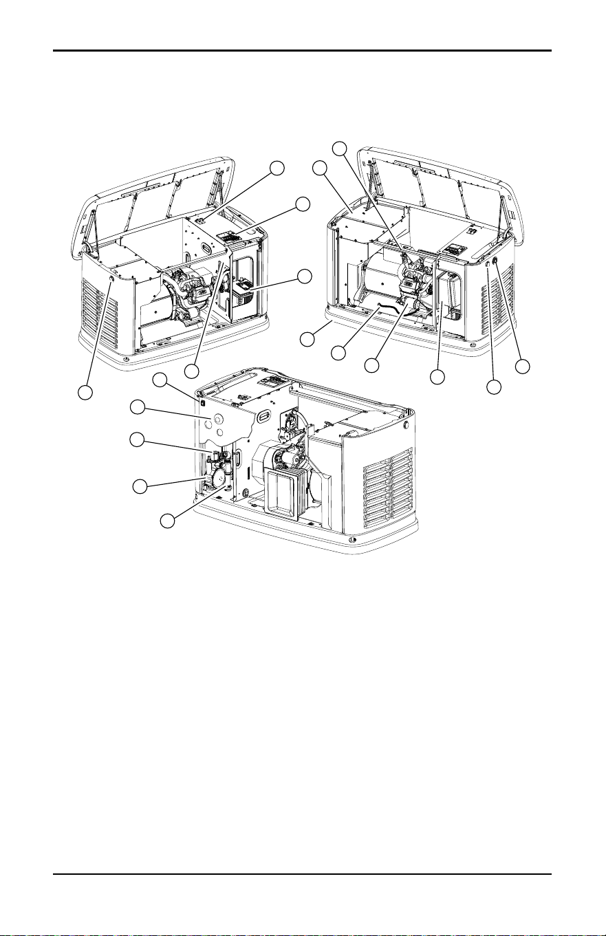
Section 2: General Information
Generator Components and Control Locations
Figure 2-1. 10 kW—Components and Control Locations
A Lock with cover G Status LED indicators N Fuel regulator
B Main line circuit breaker
(generator disconnect)
H Airbox with air cleaner O Fuel inlet
C Control panel J Oil filter P Wi-Fi module
D Battery compartment
(battery not supplied)
K Oil drain hose Q Data decal location
E Exhaust enclosure L Composite base R Generator emergency shut-
down switch
F Oil fill cap/dipstick M Sediment trap
001818
F
M
N
O
P
A
Q
D
C
B
E
L
K
J
H
A
G
R
General Information
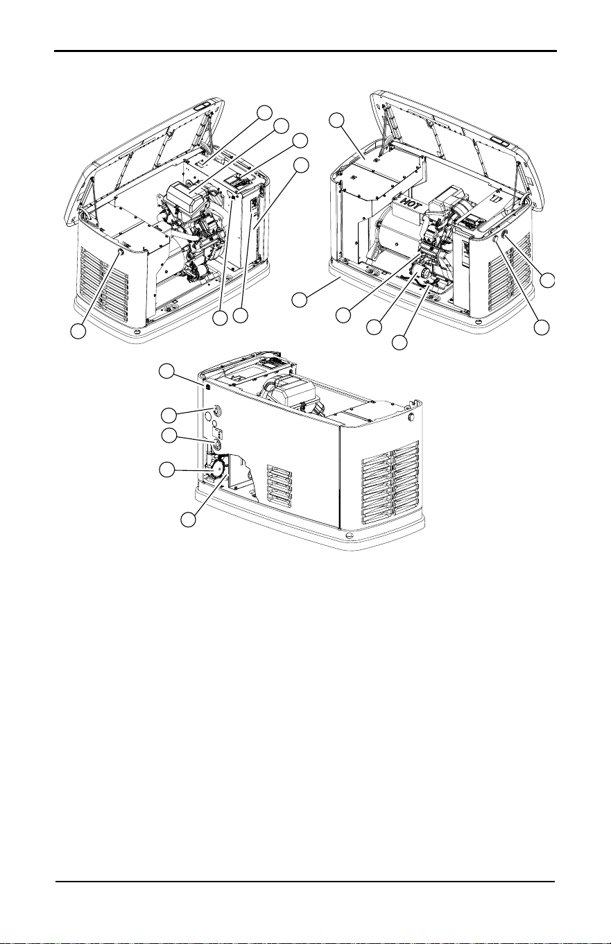
Owner’s Manual for 60 Hz Air-Cooled Generators 6
Figure 2-2. 14 kW–18 kW—Components and Control Locations
A Lock with cover G Status LED indicators N Fuel regulator
B Main line circuit breaker
(generator disconnect)
H Oil drain hose O Fuel inlet
C Airbox with air cleaner J Oil fill cap/dipstick P Wi-Fi module
D Control panel K Oil filter Q Data decal location
E Battery compartment
(battery not supplied)
L Composite base R Generator emergency shut-
down switch
F Exhaust enclosure M Sediment trap S Generator emergency shut-
down switch
009340a
C
B
G
F
E
D
A
A
L
K
J
H
P
O
N
M
S
R
Q
General Information
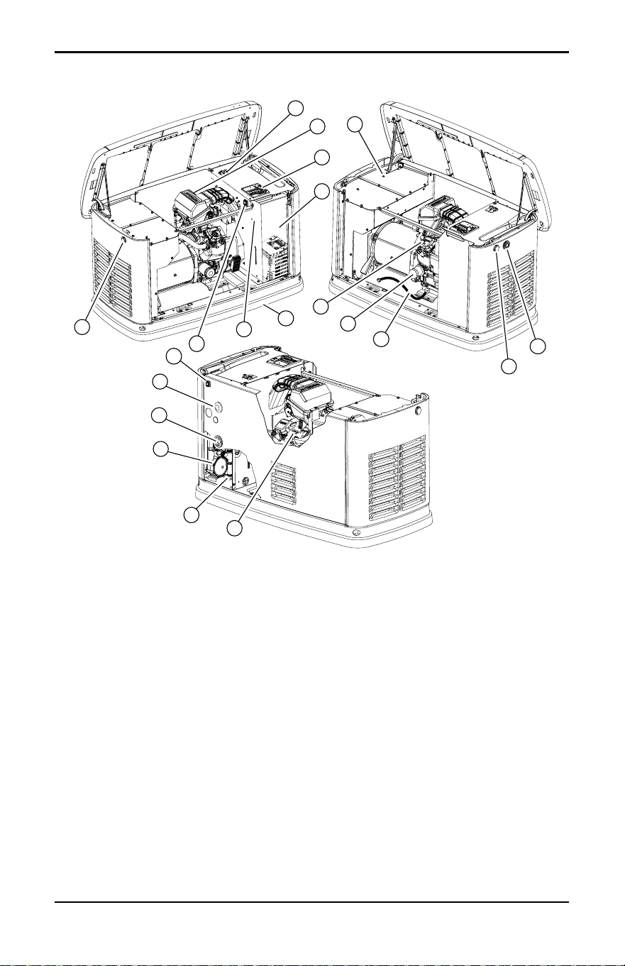
7 Owner’s Manual for 60 Hz Air-Cooled Generators
Figure 2-3. 20 kW–26 kW—Components and Control Locations
A Lock with cover H Oil drain hose P Fuel inlet
B Main line circuit breaker
(generator disconnect)
J Oil fill cap Q Wi-Fi module
C Airbox with air cleaner K Oil filter R Data decal location
D Control panel L Composite base S Generator emergency
shutdown switch
E Battery compartment
(battery not supplied)
M Oil dipstick T Generator emergency
shutdown switch
F Exhaust enclosure N Sediment trap
G Status LED indicators O Fuel regulator
001786
N
M
O
P
Q
G
K
J
F
L
R
E
A
D
C
B
A
H
T
S
General Information
Owner’s Manual for 60 Hz Air-Cooled Generators 8
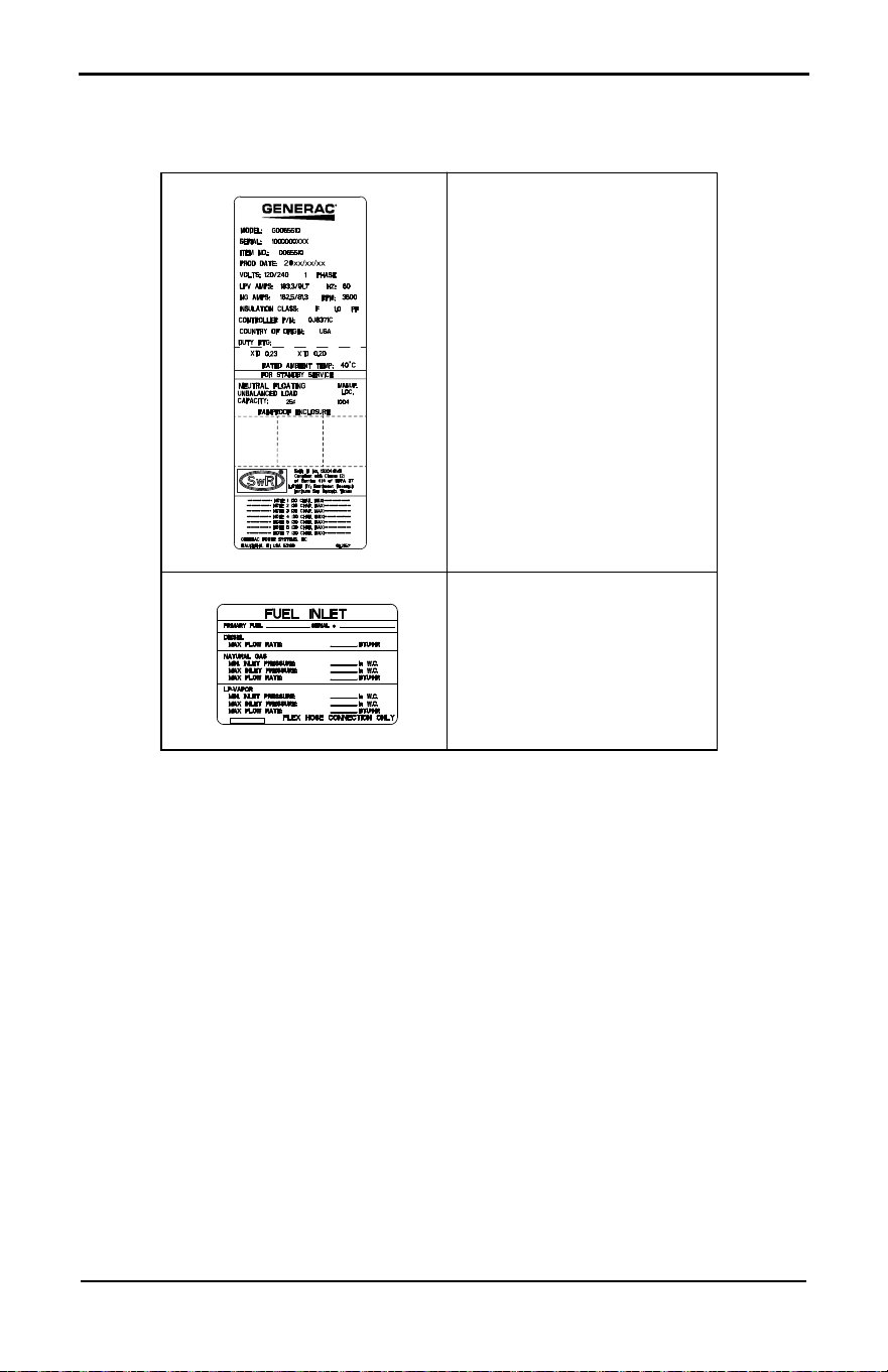
Data Decals
Two decals on the generator provide information about the unit itself and required fuel inlet pres-
sure for correct operation.
Model Data Decal
Includes important information
about the unit including:
• model number
• serial number
• production date
• voltage
• frequency
• amps
• country of origin
• rated ambient
temperature
The model data decal also displays
certification symbols by Under-
writer’s Laboratory (UL) and the
Southwest Research Institute
(SwRI).
Fuel Inlet Pressure
Displays unit serial number, along
with minimum and maximum inlet
pressures for natural gas (NG) and
liquid propane (LP) supply. Space
is provided for installer to enter
maximum flow rates based on
installed pipe sizes and lengths.
General Information
9 Owner’s Manual for 60 Hz Air-Cooled Generators
Specifications
Generator
Engine
A detailed specification sheet for a particular generator is available from a local IASD.
Model 10 kW 14 kW 18 kW 20 kW 22 kW 24 kW 26 kW
Rated voltage 240
Rated maximum load cur-
rent (amps) at rated volt-
age with LP*
41.7 58.3 75.0 83.3 91.7 100.0 108.3
Main line circuit breaker
(generator disconnect)
45 amp 60 amp 80 amp 90 amp 100 amp 110 amp
Phase 1
Rated AC frequency 60 Hz
Battery requirement
(field supplied)
0H3421S
Enclosure Aluminum
Weight (lb / kg)
(without battery)
338 / 153 385 / 175 420 / 191 436 / 198 445 / 202 455 / 206 518 / 235
Normal operating range This unit is tested in accordance to UL 2200 standards with an operating
temperature of -20 °F (-29 °C) to 122 °F (50 °C). For areas where tempera-
tures fall below 32 °F (0 °C), a cold weather kit is recommended. When oper-
ated above 77 °F (25 °C), there may be a decrease in engine power. See
Engine.
These generators are rated in accordance with UL 2200, Safety Standard for Stationary Engine Genera-
tor Assemblies, and CSA-C22.2 No. 100-04 Standard for Motors and Generators.
* NG ratings will depend on specific fuel joules/BTU content. Typical derates are between 10-20% off the
LP gas rating.
Model 10 kW 14/18 kW 20–26 kW
Engine type G-Force™ 400 Series G-Force™ 800 Series G-Force™ 1000 Series
Number of cylinders 1 2 2
Displacement 460 cc 816 cc 999 cc
Cylinder block Aluminum with cast iron sleeve
Recommended spark plug 0G0767B 0G0767A
Spark plug gap 0.020 in (0.508 mm) 0.040 in (1.02 mm)
Hydraulic lifters No Yes No
Valve clearance 0.002–0.004 in
(0.05–0.1 mm)
N/A
0.002–0.004 in
(0.05–0.1 mm)
Starter 12 VDC
Oil capacity including filter Approx. 1.1 qt (1.03 L) Approx. 2.2 qt (2.1 L) Approx. 1.9 qt (1.8 L)
Recommended oil filter 070185ES
Recommended air filter 0E9371AS 0J8478S
Engine power is subject to and limited by such factors as fuel BTU/joules, ambient temperature, and alti-
tude. Engine power decreases approximately 3.5% for each 1,000 ft (304.8 m) above sea level, and also
will decrease approximately 1% for each 10 °F (6 °C) above 60 °F (15 °C) ambient temperature.
General Information
Owner’s Manual for 60 Hz Air-Cooled Generators 10
Protection Systems
The generator may need to run for long peri-
ods of time with no operator present to moni-
tor engine or generator conditions. The
generator is equipped with protection sys-
tems to automatically shut down the unit to
protect against potentially damaging condi-
tions. Some of these systems include:
Alarms:
Warnings:
The control panel contains a display alerting
the operator when a fault condition occurs.
The above list is not all-inclusive. See Opera-
tion for more information about alarms and
control panel operation.
NOTE: A warning indicates a condition on the
generator which should be addressed, but will
not shut down generator. An alarm shuts
down the generator to protect system from
any damage. In event of an alarm, an owner
can clear the alarm and restart generator prior
to contacting an IASD. Contact an IASD if the
intermittent issue occurs again.
Emissions
The United States Environmental Protection
Agency (US EPA) (and California Air
Resources Board (CARB), for engines/equip-
ment certified to California standards)
requires this engine/equipment to comply
with exhaust and evaporative emissions
standards. Locate the emissions compliance
decal on the engine to determine applicable
standards. See the included emissions war-
ranty for emissions warranty information. Fol-
low the maintenance specifications in this
manual to ensure the engine complies with
applicable emissions standards for the dura-
tion of the product’s life.
This generator is certified to operate on liquid
propane vapor fuel or pipeline natural gas.
The Emission Control System code is EM
(Engine Modification). The Emission Control
System on this generator consists of the fol-
lowing:
:
NOTE: Under U.S. EPA regulations, a mixer
adjustment kit may be required when
operating over 2,000 ft (609.6 m) above sea
level. Contact an IASD for high altitude*
adjustment information.
*High altitude is any elevation over
2,000 ft (609.6 m).
Fuel Requirements
The engine has been fitted with a dual fuel
carburetion system. The unit will run on NG
or LP gas (vapor), but has been factory-con-
figured to run on NG. The fuel system will be
configured for the available fuel source
during installation.
Recommended fuels should have a BTU con-
tent of at least 1,000 BTUs per ft
3
(37.26
megajoules per m
3
) for natural gas, or at
least 2,500 BTUs per ft
3
(93.15 megajoules
per m
3
) for LP gas.
NOTE: If converting to LP gas from NG, a
minimum LP tank size of 250 gal (946 L) is
recommended. See installation manual for
complete procedures and details.
Battery Requirements
12 volts, Group 26R Wet Cell 540CCA (Part
number 0H3421S) minimum or Group 35
AGM 650CCA minimum.
• High Temperature
• Low Oil Pressure
• Overcrank
• Overspeed
• Overvoltage
• Undervoltage
• Overload
• Underspeed
• RPM Sensor
Loss
• Controller Fault
• Wiring Error
• Stepper
Overcurrent
• Charger Warning
• Charger Missing
AC
• Low Battery
• Battery Problem
• Exercise Set
Error
• USB Warning
• Download
Failure
System Components
Air induction - Intake manifold
- Air cleaner
Fuel metering - Carburetor and mixer
assembly
- Fuel regulator
Ignition - Spark plug
- Ignition module
Exhaust - Exhaust manifold
- Muffler
(000105)
Explosion and Fire. Fuel and vapors are extremely
flammable and explosive. Add fuel in a well
ventilated area. Keep fire and spark away. Failure
to do so will result in death or serious injury.
DANGER
General Information
11 Owner’s Manual for 60 Hz Air-Cooled Generators
Battery Charger
The battery charger is integrated into the
control panel module in all models. It oper-
ates as a smart charger, verifying output
charging levels are safe and continuously
optimized to promote maximum battery life. A
kit is provided to install a fuse in transfer
switch for T1 battery charger connection. Fol-
low installation instructions provided with kit.
NOTE: Do not use external battery chargers.
Engine Oil Requirements
See Engine Oil Requirements for correct oil
viscosity.
Activating the Generator
Generator should be activated upon initial
startup. See installation manual for complete
instructions.
Wi-Fi Module
Generator is equipped with a Wi-Fi module.
See Wi-Fi module owner’s manual for further
information.
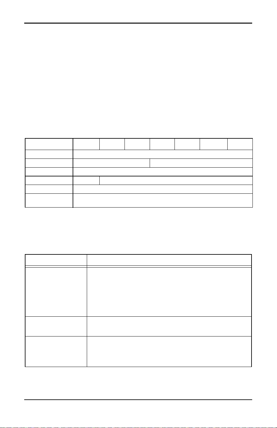
Replacement Parts
Accessories
NOTE: Performance enhancing accessories are available for air-cooled generators. Contact an
IASD or visit www.generac.com for additional information on replacement parts, accessories, and
extended warranties. See also http://www.ordertree.com/generac/air-cooled-homestandby-
generators/.
Description 10 kW 14 kW 18 kW 20 kW 22 kW 24 kW 26 kW
26R Battery 0H3421S
Spark plug 0G0767B 0G0767A
Oil filter 070185ES
Air filter 0E9371A 0J8478
Control panel fuse 0D7178T
Transfer switch
fuses
See transfer switch manual for part number
Accessory Description
Cold Weather
Accessories*
• Battery Pad Warmer
• Oil Warmer
• Breather Warmer
* each sold separately
• Recommended in areas where temperatures fall below 0 °F (-18
°C). (Not necessary for use with AGM-style batteries)
• Recommended in areas where temperatures fall below 0 °F (-18
°C).
• Recommended in areas where heavy icing occurs.
Scheduled Maintenance
Kit
Includes all items necessary to perform complete routine mainte-
nance on the generator along with oil recommendations (oil not
included).
Fascia Base Wrap The fascia base wrap snaps together around the bottom of the new
air-cooled generators. This offers a sleek, contoured appearance as
well as protection from rodents and insects by covering the lifting
holes located in the base. Requires use of the mounting pad shipped
with the generator.
General Information
Owner’s Manual for 60 Hz Air-Cooled Generators 12
Mobile Link
®
Cellular
Accessories
The Mobile Link family of Cellular Accessories allow users to monitor
generator status from anywhere in the world, using a smartphone,
tablet, or PC. Easily access information such as the current operating
status and maintenance alerts. Users can connect an account with an
authorized service dealer for fast, friendly, and proactive service. With
Mobile Link, users are taken care of before the next power outage.
Touch-Up Paint Kit If the generator enclosure is scratched or damaged, it is important to
touch-up the paint to protect from future corrosion. The touch-up paint
kit includes the necessary paint to correctly maintain or touch-up a
generator enclosure.
Extended Warranty
Coverage
Extend generator warranty coverage by purchasing extended war-
ranty coverage. Covers both parts and labor. Extended coverage can
be purchased within 12 months of the end-user’s purchase date. This
extended coverage is applicable to registered units and end-user
proof of purchase must be available upon request.
Available for Generac
®
and Guardian
®
products.
Not available for Corepower™, PowerPact
®
, and EcoGen™ products
or all international purchases.
LTE LP Fuel Level
Monitor
The LTE enabled LP fuel level monitor provides constant monitoring
of a connected LP fuel tank. Monitoring the LP tank’s fuel level is an
important step in verifying the generator is ready to run during an
unexpected power failure. Status alerts are available through a free
application to notify users when the LP tank needs a refill.
Base Plug Kit Base plugs snap into the lifting holes on the base of air-cooled home
standby generators. This offers a sleek, contoured appearance, as
well as offers protection from rodents and insects by covering the lift-
ing holes located in the base. Base plug kit contains four base plugs,
sufficient for use on a single air-cooled home standby generator.
Smart Management
Module
(50 and 100 amps)
Smart Management Modules (SMM’s) are used to optimize the per-
formance of a standby generator. They manage large electrical loads
upon startup and shed them to aid in recovery when overloaded. In
many cases, using SMM’s can reduce the overall size and cost of the
system.
High Altitude Kit A high altitude kit may be required when operating over 2,000 ft (610
m) above sea level per U.S. EPA regulations. Operating the engine
with the incorrect engine configuration at a given altitude may
increase emissions and decrease fuel efficiency and performance.
Accessory Description
Operation
13 Owner’s Manual for 60 Hz Air-Cooled Generators
Section 3: Operation
Site Prep Verification
Generator must be installed to allow unim-
peded airflow into and out of generator.
Mechanical and gravity outdoor air intake
openings for air distribution and supply sys-
tems must be located not less than 10 ft (3.05
m) horizontally from generator enclosure.
See Section 401.4 in the ICC Mechanical
Code for additional information.
Verify all shrubs or tall grasses within 3 ft
(0.91 m) of intake and discharge louvers on
the sides of the enclosure have been
removed. Install generator on high ground
where water levels will not rise and endanger
it. This unit must not operate in or be sub-
jected to standing water. Verify all potential
water sources such as water sprinklers, roof
run-off, rain gutter downspouts, and sump
pump discharges are directed away from
unit.
Generator Enclosure
Enclosure lid is locked prior to shipment. A
set of keys is attached to cardboard on top of
generator. An additional set of keys is
attached to pallet bracket on the front intake
end of generator.
NOTE: Keys provided with this unit are
intended for service personnel use only.
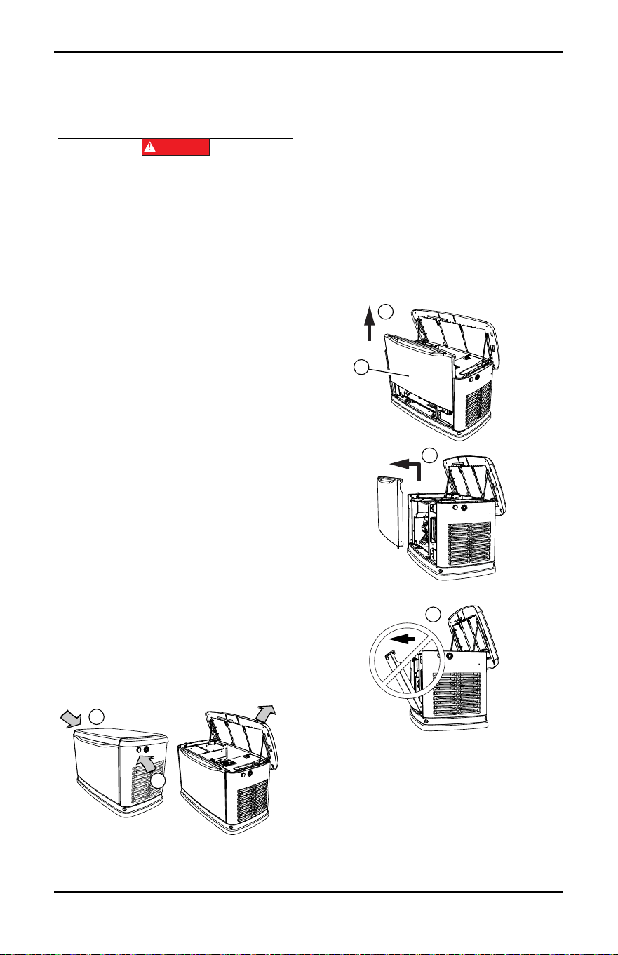
Opening the Lid
1. Use keys to open generator lid.
2. See Figure 3-1. Two locks (A) secure lid;
one on each side. Open protective rubber
cap to access keyhole.
Figure 3-1. Opening the Lid
3. Press down on lid above side lock, and
unlock latch to correctly open lid.
4. Repeat for other side. Lid may appear
stuck if pressure is not applied from the
top.
NOTE: Always verify side locks are unlocked
before attempting to lift lid.
Front Access Panel Removal
See Figure 3-2. Remove front access panel
(A) by lifting straight up and out once lid is
open.
Figure 3-2. Remove Front Access Panel
NOTE: Always lift front access panel straight
up before pulling away from enclosure (B and
C). Do not pull panel away from the enclosure
before lifting up (D).
(000191)
DANGER
Automatic start-up. Disconnect utility power and
render unit inoperable before working on unit.
Failure to do so will result in death or serious injury.
009209
A
A
009210
A
B
C
D
Operation
Owner’s Manual for 60 Hz Air-Cooled Generators 14
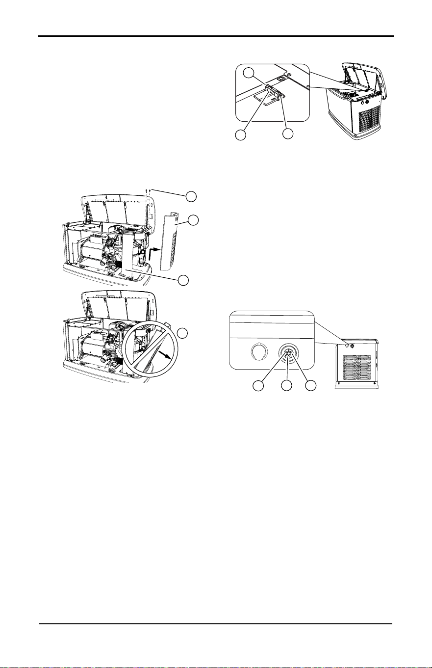
Intake Side Panel Removal
See Figure 3-3. Intake side panel (A) must be
removed to access battery compartment, fuel
regulator, and sediment trap.
1. Raise lid and remove front panel.
2. Use a hex key to remove two mounting
screws (B) and L-bracket screw (C).
3. Lift intake panel up and away from genera-
tor.
NOTE: Always lift intake side panel straight up
before pulling away from enclosure. Do not
pull panel away from enclosure before lifting
up (D).
Figure 3-3. Intake Side Panel Removal
Main Line Circuit Breaker
(Generator Disconnect)
See Figure 3-4. This is a 2-pole main line cir-
cuit breaker (MLCB) (generator disconnect)
(A) rated according to relevant specifications.
The generator MLCB (generator disconnect)
can be locked in OFF (OPEN) for security.
Use an appropriately-sized padlock (not
included) with a shackle long enough to pass
through both lock tabs (B).
Figure 3-4. Main Line Circuit Breaker
(MLCB)
NOTE: DO NOT leave generator MLCB
(generator disconnect) locked in OFF (OPEN)
during normal generator operation. Leaving
generator MLCB (generator disconnect) in
OFF (OPEN) will prevent generator from
powering structure during a power outage
when placed in AUTO mode.
LED Indicator Lights
See Figure 3-5. Three LEDs are visible
behind a translucent lens on the generator
side panel. These LEDs indicate generator
operating status.
Figure 3-5. LED Indicator Lights
• Green LED “Ready” light (A) illuminates
when utility is present and control panel is in
AUTO. LED flashes when automatic transfer
switch converts to generator power during a
utility power outage.
• Red LED “Alarm” light (B) illuminates when
generator is OFF or a fault is detected. Con-
tact an IASD.
• Yellow LED “Non-Critical Alert” light (C) illu-
minates when maintenance is required.
NOTE: Yellow LED may be illuminated at the
same time as either the red or green LED.
002961
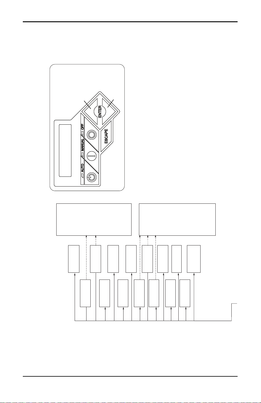
B
A
C
D
001810
A
B
B
001791
B
C
A
Operation
15 Owner’s Manual for 60 Hz Air-Cooled Generators
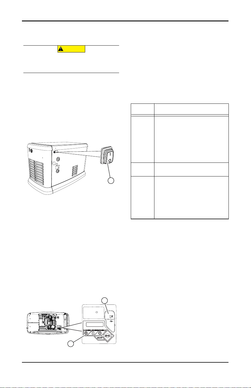
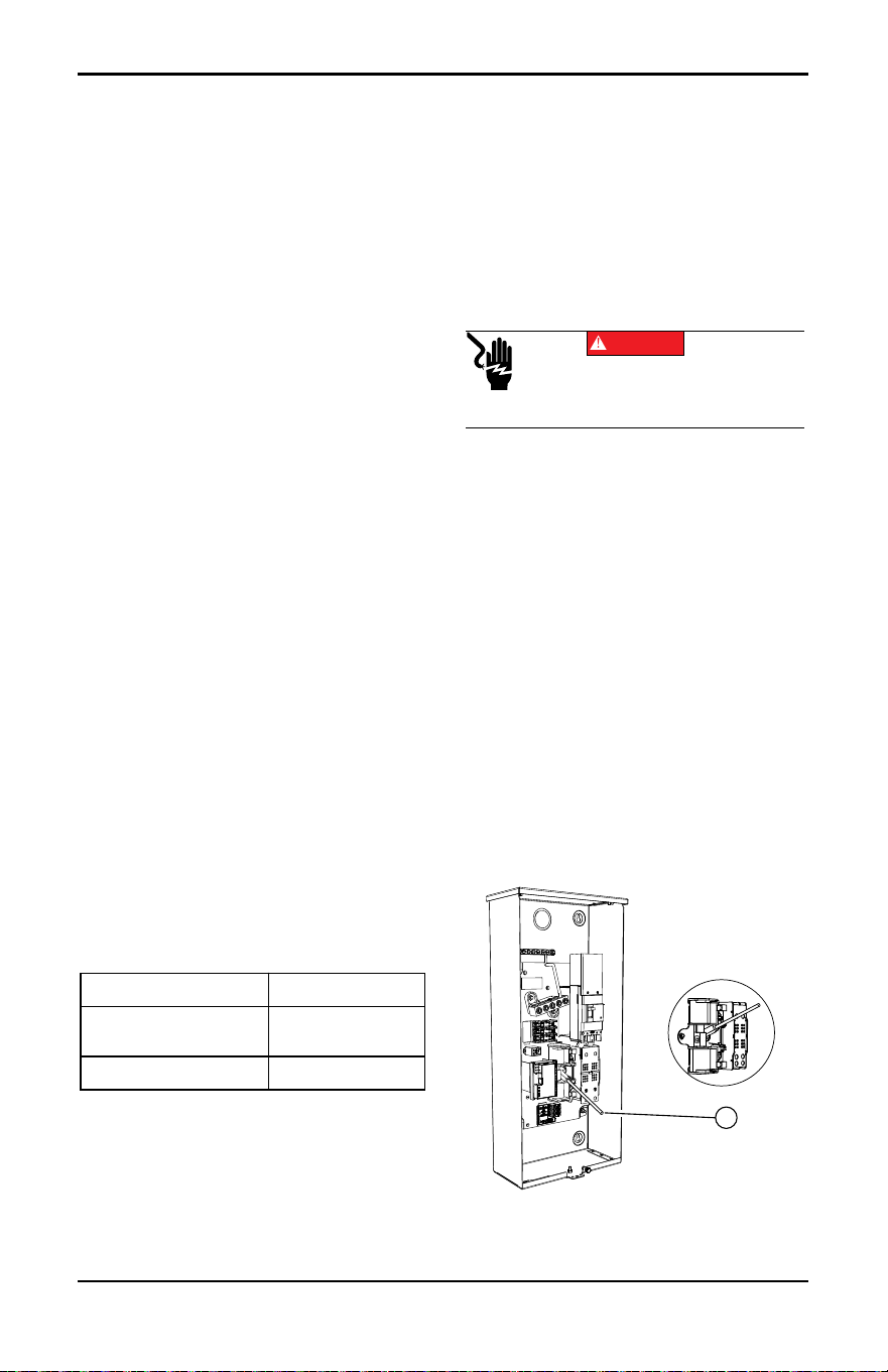
Generator Emergency
Shutdown Switch
All generators are equipped with an external
means of shutting down the generator which
complies with the latest NEC code require-
ment. Primary generator shutdown sequence
is described in Shutting Generator Down
While Under Load or During a Utility Outage.
See Figure 3-6. An emergency shutdown
switch (A) is located on the exterior of the
generator back panel. This emergency shut-
down switch shuts down generator and dis-
ables restarts.
Figure 3-6. External Emergency Shutdown
Switch (all models)
NOTE: Whenever possible, perform primary
shutdown procedure before disabling genera-
tor with emergency shutdown switch.
See Figure 3-7. 14–26 kW ge
by pressing OFF button, and then ENTER.
The generator can then be placed in AUTO
or MANUAL.
Control Panel Interface
See Figure 3-7. The control panel interface
(A) is located under the enclosure lid. Verify
both left and right side locks are unlocked
before attempting to lift lid of enclosure.
Open lid as directed in Opening the Lid.
Figure 3-7. Generator Control Panel
The 7.5A fuse is located beneath rubber
cover (B) to the right of the control panel.
Verify both left and right side locks are
securely out of the way before closing unit.
All appropriate panels must be in place
during any operation of the generator. This
includes operation by a servicing technician
while conducting troubleshooting pro-
cedures.
Using the AUTO/OFF/MANUAL
Buttons
NOTE: Damage caused by mis-wiring of
interconnect wires is not warrantable.
Equipment Damage. The emergency shutdown
switch is not to be used to power down the unit
under normal operating circumstances. Doing so
will result in equipment damage.
(000399a)
CAUTION
005492
A
001798
B
A
Button Description of Operation
AUTO Activates fully automatic system
operation. Allows unit to automati-
cally start and exercise generator
according to exercise timer (see
Setting the Exercise Timer).
Green LED flashes when auto-
matic transfer switch converts to
generator power during a utility
power outage.
OFF Shuts down engine and prevents
automatic operation of unit.
MANUAL Cranks and starts generator.
Transfer to stand-by power will not
occur unless there is a utility fail-
ure.
Blue LED flashes when automatic
transfer switch converts to gener-
ator power during a utility power
outage.
Operation
Owner’s Manual for 60 Hz Air-Cooled Generators 16
Operating Modes Interface Menu Displays
LCD PanelMode Description
MANUAL • Will not transfer to standby if
utility is present.
• Transfers to standby if utility
drops below 65% of nominal
for five consecutive seconds
(dealer programmable) after
warm-up.
• Transfers back when utility
returns for 15 consecutive
seconds (dealer program-
mable). Engine continues to
run until removed from
MANUAL.
AUTO • Starts and runs if utility
drops for five consecutive
seconds (dealer program-
mable).
• Starts an engine warm-up
timer (duration varies when
Cold Smart Start is
enabled).
–Will not transfer if utility
subsequently returns.
–Transfers to standby if util-
ity is not present.
• Transfers to utility once util-
ity returns (above 80% of
nominal) for 15 consecutive
seconds (dealer program-
mable).
• Will not transfer to utility
unless utility returns. Unit
will shut down if OFF button
is pressed or a shutdown
alarm is present.
• Unit will shut down after one
minute cool-down time
when utility power returns.
EXERCISE • Will not exercise if unit is
already running in either
AUTO or MANUAL.
• During exercise, controller
will only transfer if utility
drops during exercise for
five seconds (dealer pro-
grammable), and will switch
to AUTO.
Feature Description
HOME
page
Default page displayed if no but-
tons are pressed for 60 sec-
onds. Normally shows current
status message, and current
date and time. Highest priority
active alarm/warning is auto-
matically posted on this page,
as well as flashing the backlight
when such a condition is
detected. In the case of multiple
alarms/warnings, only first mes-
sage is displayed. Press OFF
button and then ENTER button
to clear an alarm or warning.
When “Hours of Protection” is
displayed, this represents total
time generator has been moni-
toring utility supply and ready to
provide backup power if
needed.
Display
Backlight
Normally off. The backlight will
automatically illuminate and
remain on for 30 seconds if
operator presses any button.
MAIN
MENU
page
Allows operator to navigate to
all other pages or sub-menus by
using arrow keys and ENTER
button. Page can be accessed
at any time with several presses
of the dedicated ESCAPE but-
ton. Each press of the ESCAPE
button takes operator to previ-
ous menu until MAIN MENU dis-
plays. This page contains
information for History; Status;
Edit; and Debug.
Operation
17 Owner’s Manual for 60 Hz Air-Cooled Generators
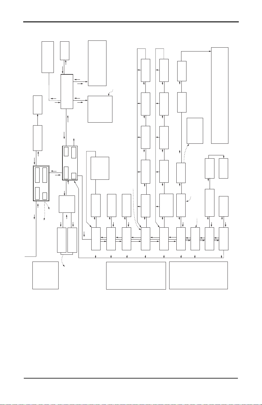
Menu System Navigation
Press ESCAPE button from any page to access the MENU. If needed, press ESCAPE button
several times to reach the MENU page. Navigate to the desired menu by using the
↑/↓ buttons.
Press ENTER button when desired menu is displayed and flashing,
Figure 3-8. Navigation Menu
EVOLUTION 2.0 / SYNC 3.0 HSB MENU MAP
Switched to “OFF”
Hours of Protection
0 (H)
Note: Menu functions and features may vary
depending on unit model and firmware revision.
* Hours of Protection and
number of hours will flash
every 5 seconds when
displayed.
*
Ready to Run
Hours of Protection
0 (H)
Utility Loss Delay
Pausing for 13 sec.
Cranking
Attempt # 3
Running in Exercise
Hours of Protection
0 (H)
Running
Cooling Down
Running - Warning
“Warning Message”
Warning Message(s)
Low Battery
Exercise Set Error
Service Schedule A
Service Schedule B
Inspect Battery
Stopping...
FIRMWARE ERROR-9
Fuel Pressure
Battery Problem
Charger Warning
Charger Missing AC
Overload Warning
SEEPROM ABUSE
USB Warning
Download Failure
Overload Warning
No WIFI Module
No WIFI Router Comms
No WIFI Server Comms
Cranking - Warning
“Warning Message”
Alarm Message(s)
High Engine Temp
Low Oil Pressure
Overcrank
Overspeed
RPM Sense Loss
Underspeed
Controller Fault
FIRMWARE ERROR-7
WIRING ERROR
Overvoltage
Undervoltage
Overload Remove Load
Low Volts Remove Load
Stepper Overcurrent
Shutdown Switch
Emergency Stop
Fuse Problem
Loss of Speed Signal
Loss of Serial Link
Stopped - Warning
“Warning Message”
Cranking
Pausing for 13 sec
Running
Hours of Protection
0 (H)
Running
Warming Up
Running - Alarm
“Alarm Message”
Cranking - Alarm
“Alarm Message”
Switched OFF
Hours of Protection
0 (H)
UP ARROW =
+
DOWN ARROW = -
006667b
Operation
Owner’s Manual for 60 Hz Air-Cooled Generators 18
Figure 3-9. Navigation Menu
Run Log
EXAMPLE:
Inspect Battery 200 RnHr or 12/27/18
and
Next Maintenance 200 RnHr or 12/27/18
Exercise Time
Å HH:MM Day Frequency Æ
ESC
+
–
++ +
–
ENTER
Current Date/Time
Å 2/12/16 12:22 Æ
ESCESCESCESC
ENTER
ESC
ENTER
ESC
ENTER
ESC
Maint. Log
Run Hrs
Scheduled
Select Month (1-12)
- 2 +
Run Hours (H)
0.0
Select Date (1-31)
- 13 +
Select Year (0-99)
- 13 +
Access
Requires Password
Language
Å English Æ
Fuel Selection
Å NG or LP Æ
Alarm Log
ENTER
ESC
ENTER
ESC
ENTER
ESC
"Battery Maintained"
"Schedule A Serviced"
"Schedule B Serviced"
"Maintenance Reset"
"Inspect Battery"
"Service Schedule A"
"Service Schedule B"
Warning Message(s)
Low Battery
Exercise Set Error
Service Schedule A
Service Schedule B
Inspect Battery
Stopping...
FIRMWARE ERROR-9
Battery Problem
Charger Warning
Charger Missing AC
Overload Cooldown
SEEPROM ABUSE
USB Warning
Download Failure
Overload Warning
No WIFI
Running Manual
Running-Utility Lost
Running–Remote Start
Running–2 Wire Start
Running–Exercise
Switched Off
Stopped - Auto
Select Min (0-59)
- 0 +
Select Hour (0-23)
- 14 +
Select Min (0-59)
- 0 +
Select Hour (0-23)
- 14 +
Quiet Test Mode ?
- YES or NO +
Select Frequency
- WEEKLY +
- BIWEEKLY +
- MONTHLY +
Language
+ English -
Fuel Selection
+ NG or LP -
Cold Smart Start?
Å YES or NO Æ
Cold Smart Start?
- YES or NO +
Language
+ Francais -
+ Espanol -
+ Português -
+ ...... -
Battery Condition
“Good”, “Inspect Battery” or
“Check Battery”
Select Day
- Wednesday +
Generator Activated
Service Unit
Language Update?
Å YES or NO Æ
WIFI Enable
Å YES or NO Æ
WIFI Enable
– YES or NO +
<ENT> LOAD LANGUAGE
<ESC> TO QUIT
ESC
ESC
ESC
ESC
ESC
ESC
ESC
ESC
Current Date/Time
10/09/18 07:40
ESC
ESC
ENTER
ESC
ENTER
ENTER
ENTER
Time Zone
Country/City
XX - XX/XX/XX XX:XX
XXXXX
XX - XX/XX/XX XX:XX
XXXXX
NOTE 1: Last 50 logs
displayed for each
(Alarm Log, Run Log,
Maint. Log).
NOTE 2: Date and time
displayed for each
occurence.
NOTE 3: Error code
displayed for each
Alarm, Error Code
and Alarm Message
swap every 5
seconds.
Battery
NOTE 1: Last 50 maintenance logs displayed.
NOTE 2: Date and time displayed for each
occurence.
(If enabled):
Refer to the Wi-Fi manual for
flow charts relating to Wi-Fi
(If not enabled): Displays SETUP WIFI
Only if Wi-Fi is disabled.
Date/Time automatically updates if connected to Wi-Fi.
Firmware Update
Å YES Æ
Current: V 1.01
USB: V 1.05
Are You Sure?
- Yes or No +
Update from:
Å USB or Wi-Fi Æ
Select YES, then press ENTER to continue or ESCAPE to cancel update. During
update process, the Blue “Manual” light flashes, then the Green “Auto” light flashes.
Sequence then repeats. When update is complete, the unit returns to Install Wizard
menu. When the controller powers up, the first screen briefly displays the version number.
When update is complete, remove USB Drive. Then follow the Install Wizard Menu.
Firmware Update
<- Insert USB ->
Possible Message(s):
Corrupted File
Invalid File
File Not Found
Unsupported Device*
* Re-try using a higher quality
USB drive. File names on the USB
cannot have more than 8 characters.
Refer to the Installation Wizard.
Only when WiFi Activated
SYSTEM
WIFI
DATE/TIME
SUB MENUS
HISTOR
Y
EDIT
MAINT
DEALER
ESC
ENTER
ESC
ENTER
ESC
ENTER
ENTER
USB
ENTER ENTER
ENTER
ENTER
ENTER ENTER
ENTER
ENTER
ENTER
ENTER
Current: V 1.01
USB: V 1.05
Are You Sure?
- Yes or No +
ENTER
ENTER
ENTER
ENTER ENTER
ENTER
ENTER
ESC
ENTER
ESC
ENTER
Alarm Message(s)
High Engine Temp
Low Oil Pressure
Overcrank
Overspeed
RPM Sense Loss
Underspeed
Internal Fault
FIRMWARE ERROR-7
WIRING ERROR
Overvoltage
Undervoltage
Overload Remove Load
Low Volts Remove Load
Stepper Overcurrent
Shutdown Switch
Emergency Stop
Defaults to English.
Select desired language
by scrolling through list.
ESC
ESCESCESCESC ESC
006667b
Operation
19 Owner’s Manual for 60 Hz Air-Cooled Generators
Setting the Exercise Timer
This generator is equipped with a configu-
rable exercise timer. Configuration can be
performed directly at the control panel or
though the Mobile Link
®
application. There
are two settings for the exercise timer:
Day/Time: Generator will start and exercise
for period defined, on day of week and at
time of day specified. During this exercise
period, unit runs for approximately five min-
utes and then shuts down.
Exercise frequency: Exercise frequency
can be set to Weekly, Biweekly, or Monthly. If
Monthly is selected, day of month must be
selected from 1–28. Generator will exercise
on that day each month. Transfer of loads to
generator output does not occur during exer-
cise cycle unless utility power is lost.
NOTE: If Wi-Fi is enabled, exercise timer will
automatically adjust for Daylight Saving Time.
NOTE: The exercise feature will operate only
when generator is in AUTO, and will not work
unless this procedure is performed. If Wi-Fi is
NOT enabled, current date/time will need to
be reset every time the 12 volt battery is
disconnected and then reconnected, and/or
when the fuse is removed.
Low Speed Exercise (Quiet-Test™) Pro-
file: Unit will run at operating speed for
approximately five seconds, then drop speed
to prepare for Quiet-Test. Speed will drop to
predetermined Quiet-Test speed after
approximately 40 seconds and continue to
run until Quiet-Test is complete, a total of five
minutes.
Table 3-1 details exercise information and
programming options for all home standby
generators.
NOTE: If Quiet-Test is disabled, generator will
exercise at the rated rpm.
Battery Charger
IMPORTANT NOTE: Contact an IASD if
controller screen displays “CHARGER
MISSING AC.”
NOTE: Battery charger is integrated into the
control module in all models.
The battery charger operates as a smart
charger which verifies:
• output is continually optimized to promote
maximum battery life.
• charging levels are safe.
NOTE: A warning is displayed on LCD when
battery needs service.
NOTE: Do not use external battery chargers.
Manual Transfer Operation
Prior to automatic operation, manually exer-
cise transfer switch to verify there is no inter-
ference with correct operation of the
mechanism. Manual operation of transfer
switch is required if electronic operation
should fail.
Transfer to Generator Power
Source
Proceed as follows to transfer to generator
power:
1. Verify generator is in OFF mode.
2. Set generator MLCB (generator discon-
nect) to OFF (OPEN).
3. Turn off utility power supply to transfer
switch using means provided (such as a
utility MLCB).
4. See Figure 3-10. Use manual transfer han-
dle (A) inside transfer switch to move main
contacts to STANDBY (loads connected to
standby power source).
Figure 3-10. Typical Manual Transfer
Switch Operation
Table 3-1. Generator Exercise
Characteristics
Generator Size 10–26 kW
Exercise Frequency
Options
Weekly/Bi-Weekly/
Monthly
Exercise Time Length 5 minutes
(000132)
Electrocution. Do not manually transfer under load.
Disconnect transfer switch from all power sources
prior to manual transfer. Failure to do so will result in
death or serious injury, and equipment damage.
DANGER
002565
A

Operation
Owner’s Manual for 60 Hz Air-Cooled Generators 20
5. Press MANUAL button on control panel to
crank and start engine.
6. Allow engine to stabilize and warm up for a
few minutes.
7. Set generator MLCB (generator discon-
nect) to ON (CLOSED). Standby power
source now powers loads.
Transfer to Utility Power Source
Shut down generator and transfer to utility
source after utility power has been restored.
Proceed as follows to manually transfer to
utility power and shut down generator:
1. Set generator MLCB (generator discon-
nect) to OFF (OPEN).
2. Run engine for one minute at no-load to
stabilize internal temperature.
3. Press OFF button on control panel. Engine
will shut down.
4. Verify utility power supply to transfer
switch is turned off.
5. Set main contacts to UTILITY (loads con-
nected to utility power source) using man-
ual transfer handle inside transfer switch.
6. Turn on utility power supply to transfer
switch using means provided (such as a
utility MLCB).
7. Press AUTO button on control panel.
8. Set generator MLCB (generator discon-
nect) to ON (CLOSED).
9. Close and lock lid.
Automatic Transfer Operation
Proceed as follows to select automatic oper-
ation:
1. Verify transfer switch main contacts are set
to UTILITY (loads connected to utility
power source).
2. Verify normal utility power source voltage
is available to loads connected to transfer
switch.
3. Press AUTO button on control panel.
4. Set generator MLCB (generator discon-
nect) to ON (CLOSED).
Generator will start automatically when utility
source voltage drops below a preset level.
Loads are transferred to standby power
source after unit starts.
Automatic Sequence of
Operation
Utility Failure
If generator is set to AUTO when utility fails
(below 65% of nominal), a five second
(dealer programmable) line interrupt delay
time is started. The engine cranks and starts
if utility power is not available when timer
expires. An engine warm-up timer will be initi-
ated once engine is started. Timer duration
varies depending on whether or not Cold
Smart Start is enabled. The controller will
transfer load to generator when warm-up
time expires. If utility power is restored
(above 80% nominal) at any time from initia-
tion of engine start until generator is ready to
accept load (warm-up time has not elapsed),
the controller completes start cycle and runs
generator through its normal cool down
cycle. However, load will remain on utility
source.
Cranking
The system will control the cyclic cranking as
follows:
• 10 kW Unit: five cranking cycles as follows:
15 seconds cranking, seven seconds rest-
ing, followed by four additional cycles of
seven seconds cranking followed by seven
seconds resting.
• 14–26 kW Units: five cranking cycles as fol-
lows: 16 seconds cranking, seven seconds
resting, 16 seconds cranking, seven sec-
onds resting, followed by three additional
cycles of seven seconds cranking followed
by seven seconds resting.
NOTE: An alarm will be triggered if generator
does not start after these five attempts.
Cold Smart Start
Cold Smart Start is factory-enabled, but can
be disabled in the EDIT menu. Generator will
monitor ambient temperature when Cold
Smart Start is enabled. The warm-up delay
will be adjusted based on prevailing condi-
tions.
See Table 3-2. If ambient temperature is
below a fixed temperature (based on model)
upon startup in AUTO, generator will warm
up for 30 seconds. This allows engine to
warm before a load is applied. The generator
will startup with normal warm-up delay of five
seconds if ambient temperature is at or
above the fixed temperature.
A check for correct output voltage buildup will
be performed when generator engine is
started.
Table 3-2. Cold Smart Start Set Points
Generator size 10–20 kW 22–26 kW
Fixed
temperature
50 °F
(10 °C)
20 °F
(-7 °C)

Operation
21 Owner’s Manual for 60 Hz Air-Cooled Generators
Cleaning Cycle
If some condition impedes normal voltage
creation, such as frost crystals or dust/dirt
preventing a good electrical connection, start
sequence will be interrupted so a cleaning
cycle of the internal electrical connections
can be attempted.
Cleaning cycle is an extended warm up
period which lasts for several minutes while
normal generator voltage output is deter-
mined to be low. During this cycle, generator
controller will display “Warming Up” on the
display screen.
The generator controller display will show
“Under Voltage” if cleaning cycle fails to clear
the obstruction. After several minutes, alarm
message can be cleared, and the generator
restarted.
If the problem persists, make no further
attempts to start. Contact an IASD.
Load Transfer
The transfer of load when generator is run-
ning is dependent upon operating mode.
Shutting Generator Down While
Under Load or During a Utility
Outage
IMPORTANT NOTE: To avoid equipment
damage, follow these steps, in order,
during utility outages. Shutdowns may be
required during utility outages to perform
routine maintenance or to conserve fuel.
To turn generator OFF:
1. Set utility MLCB to OFF (OPEN).
2. Set generator MLCB (generator discon-
nect) to OFF (OPEN).
3. Allow generator to run for cool-down for
approximately one minute.
4. Set generator to OFF at the controller.
5. Remove 7.5A fuse from controller.
To turn generator back ON:
1. Install 7.5A fuse in controller.
2. Verify generator MLCB (generator discon-
nect) is OFF (OPEN).
3. Set generator to AUTO mode at the con-
troller.
4. Generator will start and run. Allow genera-
tor to run and warm up for a few minutes.
5. Set generator MLCB (generator discon-
nect) to ON (CLOSED).
6. Set utility MLCB to ON (CLOSED).
The system now operates in automatic
mode.
Automatic start-up. Disconnect utility power and
render unit inoperable before working on unit.
Failure to do so will result in death or serious injury.
(000191)
DANGER
Maintenance
Owner’s Manual for 60 Hz Air-Cooled Generators 22
Section 4: Maintenance
Maintenance
Regular maintenance will improve perfor-
mance and extend engine/equipment life.
Generac Power Systems, Inc. recommends
that all maintenance work be performed by
an Independent Authorized Service Dealer
(IASD). Regular maintenance, replacement,
or repair of the emissions control devices and
systems may be performed by any repair
shop or person of the owner’s choosing. To
obtain emissions control warranty service
free of charge, the work must be performed
by an IASD. See the emissions warranty.
Preparing for Maintenance
Proceed as follows to prepare unit for main-
tenance:
1. Set utility MLCB to OFF (OPEN).
2. Lift lid and set generator MLCB (generator
disconnect) to OFF (OPEN).
3. If running during a utility outage, allow
generator to run and cool down for one
minute with no load.
4. Press OFF button on controller.
5. Remove 7.5A fuse from control panel.
6. Remove front panel and intake side panel.
Performing Scheduled
Maintenance
It is important to perform maintenance as
specified in the Service Schedule for correct
generator operation. Engine oil and oil filter
must be changed, and valve clearance
adjusted (where applicable, see Engine) after
first 25 hours of operation.
Emissions-critical maintenance must be per-
formed as scheduled in order for emissions
warranty to be valid. Emissions-critical main-
tenance consists of servicing the air filter and
spark plug(s) in accordance with Service
Schedule.
Controller will prompt for Schedule A or
Schedule B maintenance to be performed.
Schedule A maintenance consists of oil, oil
filter, and battery check. Schedule B mainte-
nance includes oil, oil filter, battery check, air
cleaner, spark plug(s), and valve clearance
(where applicable, see Engine).
Since most maintenance alerts occur at the
same time (most have two year intervals),
only one will appear on control panel display
at a time. Once first alert is cleared, the next
active alert will be displayed.
(000191)
DANGER
Automatic start-up. Disconnect utility power and
render unit inoperable before working on unit.
Failure to do so will result in death or serious injury.
(000182a)
WARNING
Equipment damage. Only qualified service personnel may
install, operate, and maintain this equipment. Failure to
follow proper installation requirements could result in death,
serious injury, and equipment or property damage.
Maintenance
23 Owner’s Manual for 60 Hz Air-Cooled Generators
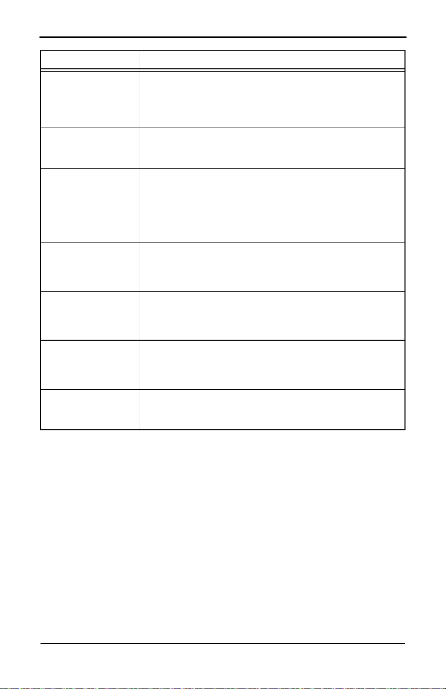
Service Schedule
NOTE: Contact an IASD or visit www.generac.com for additional information on replacement
parts.
Maintenance Log
Battery Inspection and Charge Check
Dates Performed:
Oil, Oil Filter, Air Filter, and Spark Plug Replacement
Dates Performed:
Service
Daily If Running
Continuously or
Before Each Use
Every
Year
Schedule A
Every Two
Years or
200 Hours
Schedule B
Every Four
Years
or 400 Hours
Inspect enclosure louvers for dirt and
debris *
●
Inspect lines and connections for fuel or
oil leaks
●
Check engine oil level ●
Inspect for water intrusion ** ●
Perform fuel system leak test ●
Check battery condition ●
Replace engine oil and oil filter † ● ●
Replace engine air filter ●
Replace spark plug(s) ●
Inspect/adjust valve clearance (where
applicable) ‡
●
Inspect/clean sediment trap See local codes and guidelines.
Contact the nearest IASD for assistance if necessary.
* Remove any shrubs or tall grasses which have grown within 3 ft (0.91 m) of intake and discharge lou-
vers on enclosure sides. Clean any debris (dirt, grass clippings, etc.) which may have accumulated
inside enclosure.
** Verify all sources of potential water intrusion such as water sprinklers, roof run-off, rain gutter down-
spouts, and sump pump discharges are directed away from generator enclosure.
† Change engine oil and filter after first 25 hours of operation. In cold weather conditions (ambient below
40 °F [4.4 °C]), or if unit is operated continuously in hot weather conditions (ambient above 85 °F [29.4
°C]), change engine oil and filter every year or 100 hours of operation.
‡ Inspect/adjust valve clearance after first 25 hours of operation. (Excludes units with hydraulic lifters.
See Engine.)
Maintenance
Owner’s Manual for 60 Hz Air-Cooled Generators 24
Valve Adjustment
NOTE: Not required on 14 or 18 kW units with 816cc engines.
Dates Performed:
Checking Engine Oil Level
IMPORTANT NOTE:
Verify oil level daily
when power outages necessitate running
generator for extended periods. Generator
will shut down if oil level is low
.
Proceed as follows to check engine oil level:
1. Set utility MLCB to OFF (OPEN).
2. Set generator MLCB (generator discon-
nect) to OFF (OPEN).
3. Allow generator to run for a cool-down
period of approximately one minute, if
generator was running during an outage.
4. Press OFF button to turn generator off.
Wait five minutes.
5. See Figure 2-1, Figure 2-2, or Figure 2-3.
Remove oil dipstick and wipe it dry with a
clean cloth.
6. Completely insert oil dipstick into oil dip-
stick tube and remove.
7. Observe oil level. Oil level should be at
FULL mark on oil dipstick.
8. If necessary, remove oil fill cap and add
recommended oil to engine (with oil dip-
stick removed) until oil level reaches FULL
mark. Insert oil dipstick and install fill cap.
See Engine Oil Requirements.
To restart generator:
1. Press AUTO button on control panel.
2. Allow generator to start and warm up for a
few minutes.
3. Set generator MLCB (generator discon-
nect) to ON (CLOSED).
The system is now operating in AUTO. The
utility MLCB can be turned ON (CLOSED).
Engine Oil Requirements
Engine oil should be serviced in accordance
with the recommendations of this manual to
maintain product warranty. Generac mainte-
nance kits consisting of engine oil, oil filter,
air filter, spark plug(s), a shop towel, and a
funnel are available through an IASD.
All Generac oil kits meet minimum American
Petroleum Institute (API) Service Class SJ,
SL, or better. Do not use special additives.
After the 25 hour break-in period (and at
every interval there-after), it is recommended
to use Generac’s proprietary 5W-20 gaseous
engine oil (GEO) for continuous use. It is
specifically formulated for use in gaseous
powered Generac generators.
Changing the Oil and Oil Filter
Proceed as follows to change oil and oil filter:
1. Lift lid and press MANUAL button on con-
trol panel to start engine, and run unit until
it is thoroughly warmed up. Press OFF
button on control panel to shut down
engine.
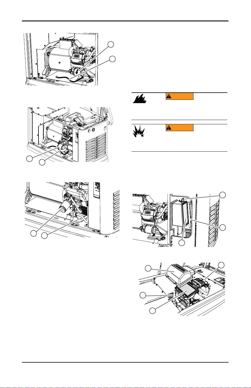
2. See Figure 4-1, Figure 4-2, or Figure 4-3.
Remove front panel when unit has cooled.
Pull oil drain hose (A) free of retaining clip.
Remove cap from oil drain hose and place
free end into a suitable container. Drain
oil.
(000139)
WARNING
Risk of burns. Allow engine to cool before
draining oil or coolant. Failure to do so could
result in death or serious injury.
(000210)
WARNING
Skin irritation. Avoid prolonged or repeated contact with
used motor oil. Used motor oil has been shown to cause
skin cancer in laboratory animals. Thoroughly wash
exposed areas with soap and water.
(000135)
Engine damage. Verify proper type and quantity of
engine oil prior to starting engine. Failure to do so
could result in engine damage.
CAUTION
(000135)
Engine damage. Verify proper type and quantity of
engine oil prior to starting engine. Failure to do so
could result in engine damage.
CAUTION
Maintenance
25 Owner’s Manual for 60 Hz Air-Cooled Generators
Figure 4-1. Oil Filter and Drain Location
(10 kW)
Figure 4-2. Oil Filter and Drain Location
(14–18 kW)
Figure 4-3. Oil Filter and Drain Location
(20–26 kW)
3. Install cap on oil drain hose. Position and
secure oil drain hose with the retaining
clip.
4. Remove oil filter (B) by turning it counter-
clockwise.
5. Apply a light coating of clean engine oil to
gasket of new filter.
6. Screw new filter on by hand until gasket
lightly contacts oil filter adapter. Tighten fil-
ter an additional three-quarter to one full
turn.
7. Fill engine with recommended oil. See
Engine Oil Requirements.
8. Press MANUAL button on control panel to
start engine. Run for one minute, and
inspect for leaks.
9. Press OFF button on control panel to stop
engine. Wait five minutes.
10.Inspect oil level. Add oil as needed. DO
NOT OVERFILL.
11. Insert oil dipstick and/or attach fill cap.
12.Press AUTO button on control panel to
return unit to AUTO.
13.Close and lock lid.
14.Dispose of used oil and filter according to
local, state, or national codes.
Servicing the Air Cleaner
Proceed as follows to service air cleaner:
1. Lift lid and press OFF button on control
panel to stop generator.
2. Remove front panel.
3. See Figure 4-4 or Figure 4-5. Remove
cover clips (A) and air cleaner cover (B).
Figure 4-4. Servicing Air Cleaner (10 kW)
Figure 4-5. Servicing Air Cleaner
(14–26 kW)
4. Remove old air filter element (C) and dis-
card.
5. Thoroughly clean air cleaner enclosure of
any dust or debris.
001831
A
B
009342
A
B
009343
A
B
(000249)
WARNING
Risk of fire. Never operate engine without the
air cleaner installed. Operating engine without
the air cleaner could result in death or serious
injury.
(000580)
WARNING
Explosion and fire. Never clean air filter element
with gasoline or low flash-point detergents. Doing
so could result in death, serious injury, or
equipment damage.
001820
B
C
A
001814
D
C
B
A
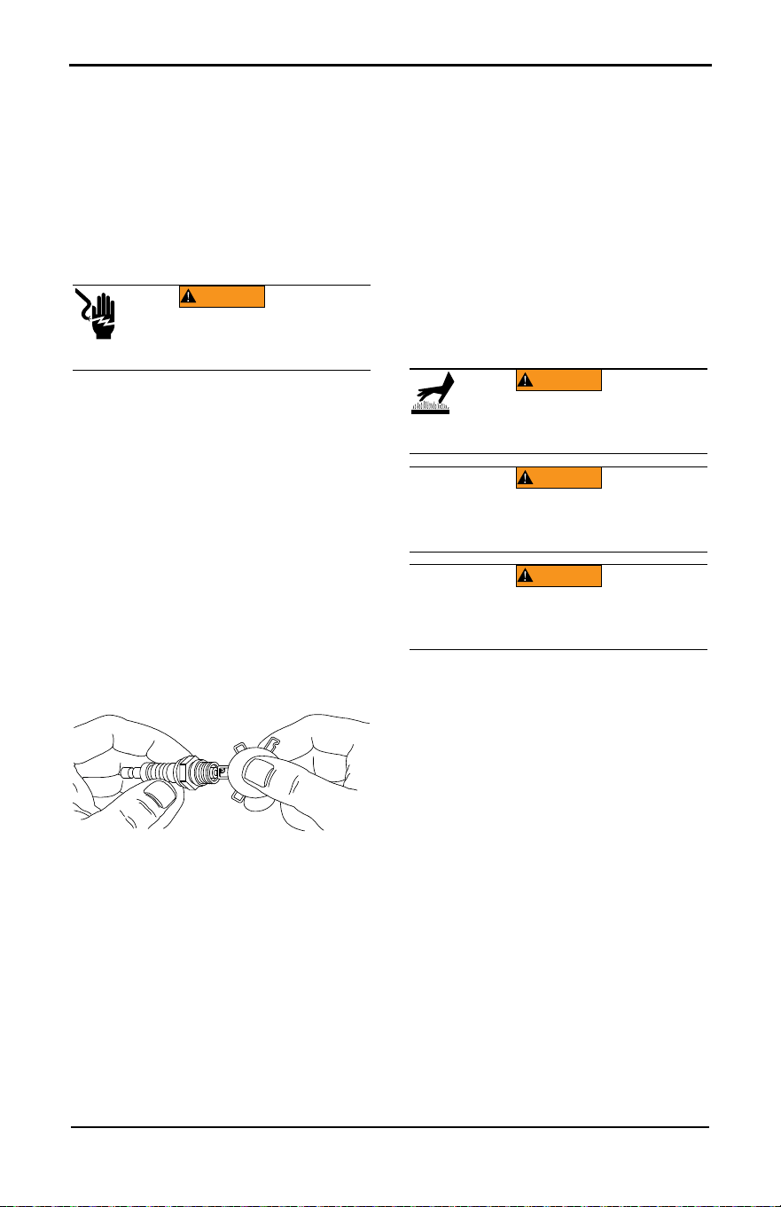
Maintenance
Owner’s Manual for 60 Hz Air-Cooled Generators 26
6. Install a new air filter element.
7. Install air cleaner cover and fasten cover
clips.
8. (14–26 kW units only): Verify air inlet
duct (D) is correctly connected to air
cleaner cover.
9. Press AUTO button on control panel to
return unit to AUTO.
Spark Plug(s)
Proceed as follows to inspect spark plug
gap(s) and replace spark plug(s):
1. With generator OFF and engine cool, lift lid
and remove front panel.
2. Clean area around base of spark plug(s) to
keep dirt and debris out of engine.
NOTE: Clean and re-gap spark plug(s) in
emergency situations only. Otherwise, replace
spark plug(s).
3. Remove spark plug(s) and inspect spark
plug gap(s) using a wire feeler gauge.
Replace spark plug(s) if spark plug gap is
out of specification. See Engine.
NOTE: See Figure 4-6. New spark plug(s)
should have spark plug gap checked prior to
installation.
Figure 4-6. Spark Plug Gap Measurement
4. Install spark plug(s), and tighten to 18.4 ft-
lbs (25 Nm).
5. Press AUTO button to return unit to AUTO
mode.
Valve Clearance Adjustment
IMPORTANT NOTE: Contact an IASD for
service assistance. Correct valve clear-
ance is essential for prolonging the life of
the engine. Excludes units equipped with
hydraulic lifters. See Engine.
IMPORTANT NOTE: Valve lash not
required on 14 or 18 kW units with 816cc
engine. See Engine.
Inspect valve clearance after first 25 hours of
operation, then after 400 hour intervals.
Adjust if necessary.
Checking Valve Clearance
NOTE: Engine should be cool before checking
valve clearance. Adjustment is not needed if
valve clearance is within dimensions provided
in Engine.
Proceed as follows to check valve clearance.
1. Close fuel valve and disconnect battery to
avoid accidental startup.
2. Remove spark plug wire(s), and position
spark plug wire(s) away from spark
plug(s).
3. Remove spark plug(s).
4. Remove the four screws attaching the
valve cover. Remove and discard gasket.
(Repeat for second cylinder, if equipped.)
5. Verify piston is at top dead center (TDC) of
its compression stroke (both valves
closed).
NOTE: To move piston to TDC, remove intake
baffle at front of the engine to access the
flywheel nut. Use a large socket and socket
wrench to rotate flywheel nut clockwise, which
will rotate the crankshaft. Watch piston
through spark plug hole. Piston will move up
and down. Piston is at TDC when at its
highest point of travel.
(000140a)
WARNING
Electric shock. Do not disconnect spark
plug wires with engine running. Doing so
could result in death or serious injury.
000211
WARNING
(000560)
Risk of Burn. Allow the engine to cool before
performing the following procedure. Failure
to do so could result in serious injury.
(000130)
Accidental Start-up. Disconnect the negative battery
cable, then the positive battery cable when working
on unit. Failure to do so could result in death
or serious injury.
WARNING
(000141)
WARNING
Accidental start-up. Disconnect spark plug wires when
working on unit. Failure to do so could result in death
or serious injury.
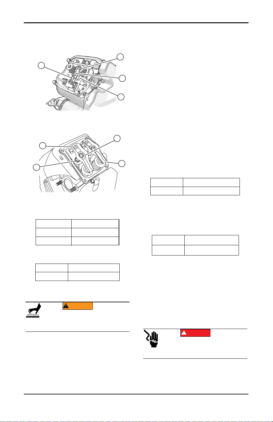
Maintenance
27 Owner’s Manual for 60 Hz Air-Cooled Generators
6. See Figure 4-7 or Figure 4-8. Verify valve
clearance between each rocker arm (A)
and valve stem (B) with a feeler gauge.
.
Figure 4-7. Valve Clearance Adjustment
(10 kW)
Figure 4-8. Valve Clearance Adjustment
(20–26 kW)
7. Install replacement valve cover gasket(s).
8. Install valve cover(s). Tighten fasteners in
a cross pattern, tightening to:
Adjusting Valve Clearance
IMPORTANT NOTE: Valve lash not
required on 14 or 18 kW units with 816cc
engine. See Engine.
See Figure 4-7 or Figure 4-8. Proceed as fol-
lows to ad-just valve clearance:
NOTE: Allow engine to cool before adjusting
valve clearance.
1. Remove spark plug wire(s) and position
spark plug wire(s) away from spark
plug(s).
2. Remove spark plug(s).
3. Remove the four screws attaching valve
cover. Remove and discard gasket.
4. Verify piston is at TDC of its compression
stroke (both valves closed).
5. Loosen rocker jam nut (C) using a 10 mm
wrench (10 kW units) or 13 mm wrench
(20–26 kW units).
6. Turn pivot ball stud (D) using a 14 mm
wrench (10 kW units), or 10 mm hex key
(20–26 kW units) while inspecting clear-
ance between rocker arm (A) and valve
stem (B) with a feeler gauge. Adjust clear-
ance as per Engine.
NOTE: Hold rocker jam nut in place as pivot
ball stud is turned.
7. When valve clearance is correct, hold
pivot ball stud in place with a wrench and
tighten rocker arm jam nut. Tighten jam
nut according to:
8. Inspect valve clearance to verify it did not
change.
9. Install new valve cover gasket.
10.Install valve cover. Tighten fasteners in a
cross pattern. Tighten to:
NOTE: Start all four screws before tightening,
or it will not be possible to get all screws in
place. Verify valve cover gasket is in place.
11. Install spark plug(s) and tighten to 18 ft-lbs
(25 Nm).
12.Attach spark plug wire(s) to spark plug(s).
13.Repeat process for other cylinder if
equipped.
Battery Maintenance
10 kW 0K8946
14–18 kW 10000014927
20–26 kW 0C2979
10 kW 80 in-lbs (9.0 Nm)
20–26 kW 60 in-lbs (6.8 Nm)
001812
D
C
B
A
002380
D
C
B
A
WARNING
(000560)
Risk of Burn. Allow the engine to cool before
performing the following procedure. Failure
to do so could result in serious injury.
10 kW 53 in-lbs (6.0 Nm)
20–26 kW 174 in-lbs (19.68 Nm)
10 kW 80 in-lbs (9.0 Nm)
20–26 kW 60 in-lbs (6.8 Nm)
(000188)
DANGER
Electrocution. Do not wear jewelry while
working on this equipment. Doing so will
result in death or serious injury.
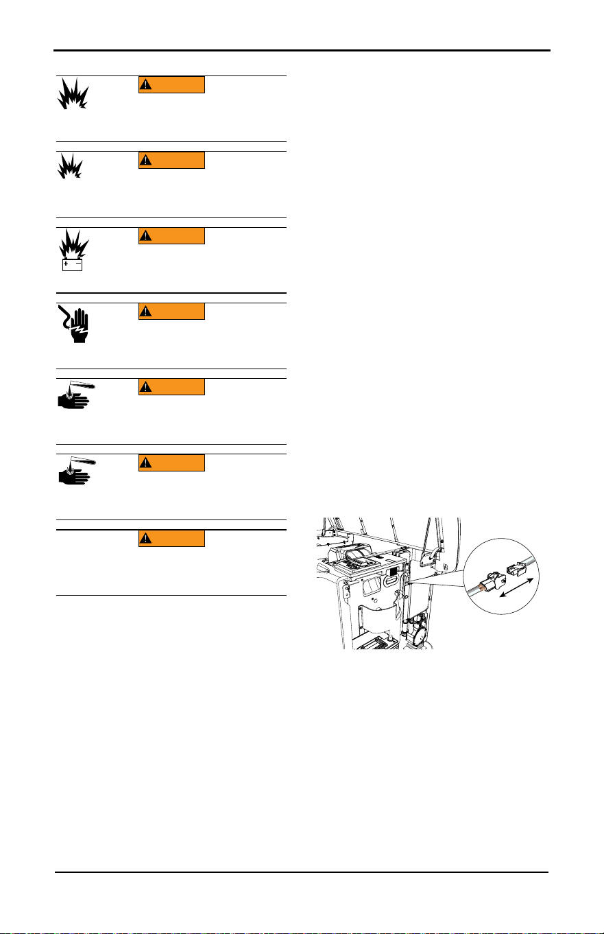
Maintenance
Owner’s Manual for 60 Hz Air-Cooled Generators 28
Always recycle batteries in accordance with
local laws and regulations. Contact your local
solid waste collection site or recycling facility
to obtain information on local recycling pro-
cesses. For more information on battery
recycling, visit the Battery Council Interna-
tional website at: http://batterycouncil.org.
Strictly observe the following precautions
when working on batteries:
• Remove 7.5A fuse from generator control
panel.
• Disconnect battery charger as directed in
Inspecting the Battery.
• Use tools with insulated handles.
• Wear rubber gloves and boots.
• Do not place tools or metallic objects on top
of battery.
• Disconnect charging source prior to con-
necting or disconnecting battery terminals.
• Wear full eye protection and protective cloth-
ing.
• If electrolyte contacts skin, wash it off imme-
diately with water.
• If electrolyte contacts eyes, flush thoroughly
with water immediately and seek medical
attention.
• Wash down spilled electrolyte with an acid
neutralizing agent. A common practice is to
use a solution of 1 lb (454 g) bicarbonate of
soda to 1 gal (3.8 L) of water. Add bicarbon-
ate of soda solution until evidence of reac-
tion (foaming) has ceased. Flush resulting
liquid with water and dry area completely.
• DO NOT smoke near battery.
• DO NOT cause flame or spark in battery
area.
• Discharge static electricity from the body
before touching battery by first touching a
grounded metal surface.
Battery should be regularly inspected per
Service Schedule. Contact an IASD for assis-
tance if necessary.
Inspecting the Battery
Proceed as follows to inspect battery:
1. Press OFF button to shut down generator,
then lift lid and remove front panel.
2. Remove 7.5A fuse from control panel.
3. Remove intake side panel. (See Intake
Side Panel Removal.)
4. See Figure 4-9. Disconnect white battery
charger cable.
Figure 4-9. Disconnecting Battery Charger
Cable
5. See Figure 4-10. Inspect battery posts and
cables for tightness and corrosion. Tighten
and clean as necessary.
(000162)
Explosion. Do not dispose of batteries in a fire.
Batteries are explosive. Electrolyte solution can cause
burns and blindness. If electrolyte contacts skin or eyes,
flush with water and seek immediate medical attention.
WARNING
(000137a)
WARNING
Explosion. Batteries emit explosive gases while
charging. Keep fire and spark away. Wear protective
gear when working with batteries. Failure to do so
could result in death or serious injury.
(000238)
Explosion. Batteries emit explosive gases.
Always disconnect negative battery cable
first to avoid spark. Failure to do so could
result in death or serious injury.
WARNING
(000164)
WARNING
Electrical shock. Disconnect battery ground
terminal before working on battery or battery
wires. Failure to do so could result in death
or serious injury.
(000138a)
WARNING
Risk of burns. Batteries contain sulfuric acid and can
cause severe chemical burns. Wear protective gear
when working with batteries. Failure to do so could
result in death or serious injury.
(000163a)
Risk of burn. Do not open or mutilate batteries.
Batteries contain electrolyte solution which can cause
burns and blindness. If electrolyte contacts skin or
eyes, flush with water and seek immediate medical
attention.
WARNING
WARNING
(000228)
Environmental Hazard. Always recycle batteries at an
official recycling center in accordance with all local
laws and regulations. Failure to do so could result in
environmental damage, death, or serious injury.
002389
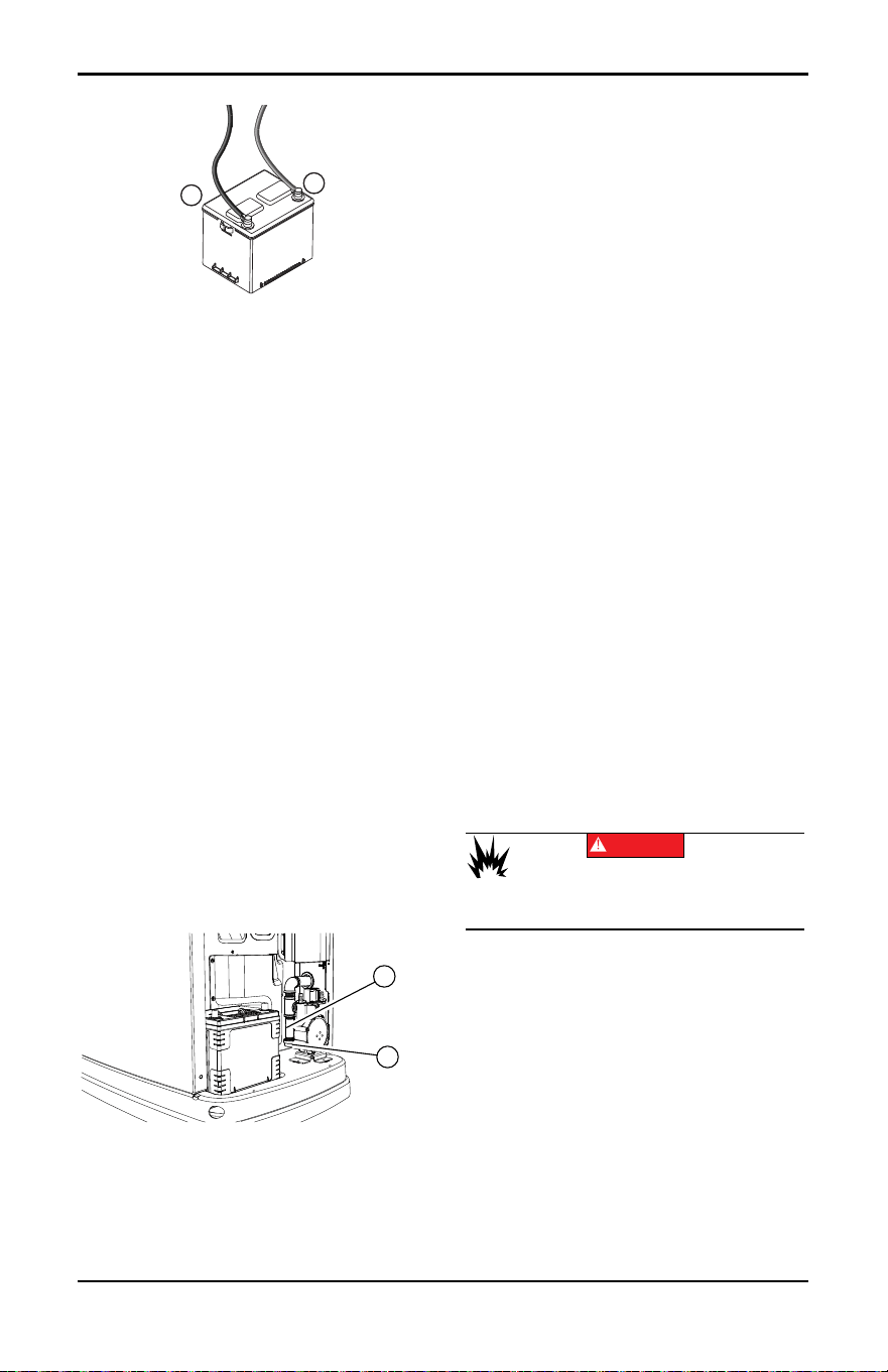
Maintenance
29 Owner’s Manual for 60 Hz Air-Cooled Generators
Figure 4-10. Battery Cables
6. Unsealed batteries only: Completely dis-
connect battery, removing negative battery
cable first. Check battery fluid level and, if
necessary, fill with distilled water only. DO
NOT use tap water. Have an IASD or a
qualified service technician verify state of
charge and condition.
7. Connect positive battery cable, then nega-
tive battery cable.
8. Connect battery charger cable.
9. Install intake side panel, and install 7.5 A
fuse.
10.Press AUTO button on controller.
11. Install front panel and close generator lid.
Cleaning the Sediment Trap
The sediment trap removes contaminants
(moisture and fine particles) from gaseous
fuels before they enter the fuel regulator.
Accumulated moisture and particles must be
emptied from the sediment trap per local
codes and guidelines.
Proceed as follows to clean sediment trap:
1. Remove intake side panel. See Intake
Side Panel Removal.
2. Turn generator fuel supply OFF.
3. See Figure 4-11. Unscrew and remove cap
(A).
Figure 4-11. Cleaning the Sediment Trap
4. Use a clean-out tool (not provided) to
remove accumulated moisture and parti-
cles from cap and body (B).
5. Wipe inside of each component with a
clean, dry, lint-free cloth.
6. Seal threads of cap with appropriate seal-
ing compound. Install cap and hand-
tighten.
7. Tighten cap with an appropriately sized
pipe wrench. DO NOT overtighten.
8. Turn generator fuel supply ON. Inspect for
leaks by spraying all connection points
with a non-corrosive gas leak detection
fluid. Solution should not be blown away
or form bubbles.
9. Install intake side panel.
Post Maintenance Checks
Proceed as follows to perform post mainte-
nance checks:
1. Perform required maintenance proce-
dure(s).
2. Install intake side panel and front panel if
removed. (See Intake Side Panel Removal
and Front Access Panel Removal.)
3. Install 7.5A fuse in control panel.
4. Complete Install Wizard information.
5. Press AUTO button on control panel.
Allow unit to run for one minute with no
load (if running during a utility outage).
6. Set generator MLCB (generator discon-
nect) to ON (CLOSED).
7. Set utility MLCB to ON (CLOSED).
The system is now in AUTO.
NOTE: If correct utility is present at this time,
generator will perform its usual shutdown
process.
Performing Fuel System Leak Test
All products are factory-tested before ship-
ping to verify the performance and integrity of
the fuel system. However, it is important to
perform a final fuel system leak test before
starting the generator. The entire fuel system
should be tested from supply to regulator.
See Figure 4-12. Perform a final fuel system
leak test after generator installation. The test
will identify possible leaks at all connection
points (A).
It is best practice to perform a fuel system
leak test during normally-scheduled mainte-
nance.
–
+
001832
001821
A
B
(000192)
DANGER
Explosion and fire. Fuel and vapors are extremely
flammable and explosive. No leakage of fuel is
permitted. Keep fire and spark away. Failure to do
so will result in death or serious injury.
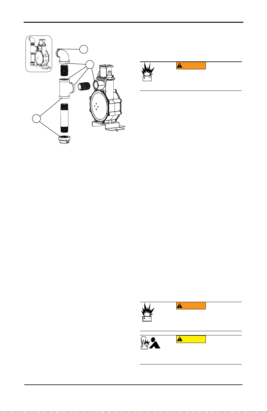
Maintenance
Owner’s Manual for 60 Hz Air-Cooled Generators 30
Figure 4-12. Connection Points to Leak
Check
Inspect for leaks by spraying all connection
points with a non-corrosive gas leak detec-
tion fluid. The solution should not be blown
away or form bubbles.
Attention After Submersion
DO NOT start or operate generator if it has
been submerged in water. Have an IASD
thoroughly clean, dry, and inspect generator
following any submersion in water. If the
structure (home) has been flooded, it should
be inspected by a certified electrician to ver-
ify there will not be any electrical problems
during generator operation or when utility
power is returned.
Corrosion Protection
Regular scheduled maintenance should be
conducted to inspect unit for corrosion.
Inspect all metal components of generator,
including base frame, brackets, alternator
can, the entire fuel system (inside and out-
side of the generator), and fastener locations.
If there is corrosion found on generator com-
ponents (e.g. regulator, engine/alternator
mounts, fuel plenum, etc.), replace parts as
necessary.
Periodically wash and wax enclosure using
automotive type products. Do not spray unit
with a hose or power washer. Use warm,
soapy water and a soft cloth. Frequent wash-
ing is recommended in salt water/coastal
areas. Spray engine linkages with a light oil
such as WD-40.
Remove From and Return To
Service Procedure
Remove From Service
If generator cannot be exercised monthly, at
a minimum, and will be out of service longer
than 90 days, proceed as follows to prepare
generator for storage:
1. Start engine and allow it to warm up.
2. Close fuel shutoff valve in fuel supply line
and allow engine to stop.
3. Set generator MLCB (generator discon-
nect) to OFF (OPEN) once engine has
stopped.
4. Disconnect battery charger AC input T1/
Neutral cable (with white sleeve) at con-
troller.
5. Remove 7.5A fuse from generator control
panel.
6. Disconnect battery cables. Remove nega-
tive battery cable first.
7. Drain oil completely while engine is still
warm, and then fill crankcase with oil. See
Changing the Oil and Oil Filter.
8. Attach a tag to engine indicating viscosity
and classification of the new oil in the
crankcase.
9. Remove spark plug(s) and spray a fogging
agent into spark plug(s) threaded open-
ings. Install and tighten spark plug(s) to
specification.
10.Remove battery and store in a cool, dry
place.
11. Clean and wipe down generator enclo-
sure.
Return to Service
Proceed as follows to return unit to service
after storage:
004038
A
A
A
(000238)
Explosion. Batteries emit explosive gases.
Always disconnect negative battery cable
first to avoid spark. Failure to do so could
result in death or serious injury.
WARNING
(000133)
WARNING
Explosion. Batteries emit explosive gases.
Always connect positive battery cable first to
avoid spark. Failure to do so could result in
death or serious injury.
(000167a)
Equipment damage. Do not make battery
connections in reverse. Doing so will result
in equipment damage.
CAUTION

Maintenance
31 Owner’s Manual for 60 Hz Air-Cooled Generators
1. Inspect engine tag for oil viscosity and
classification. Drain and fill with recom-
mended oil if necessary.
2. Verify state of battery. Fill all cells of
unsealed batteries to correct level with dis-
tilled water. DO NOT use tap water.
Charge battery to 100% state of charge.
Replace battery if faulty.
3. Clean and wipe down generator enclo-
sure.
4. Verify 7.5A fuse is removed from genera-
tor control panel.
5. Connect battery. Observe battery polarity.
Damage will occur if battery is connected
incorrectly. Install positive battery cable
first.
6. Connect battery charger AC input T1/Neu-
tral cable (with white sleeve) at controller.
7. Open fuel shutoff valve.
8. Insert 7.5 A fuse into generator control
panel.
9. Complete Install Wizard procedure (dia-
grammed in generator installation man-
ual).
10.Press MANUAL button to start unit. Allow
unit to warm up for a few minutes.
11. Press OFF button to stop unit.
12.Set generator MLCB (generator discon-
nect) to ON (CLOSED).
13.Press AUTO button on control panel.
The generator is ready for service.
NOTE: Exercise timer and current date and
time must be reset if battery is discharged or
has been disconnected.
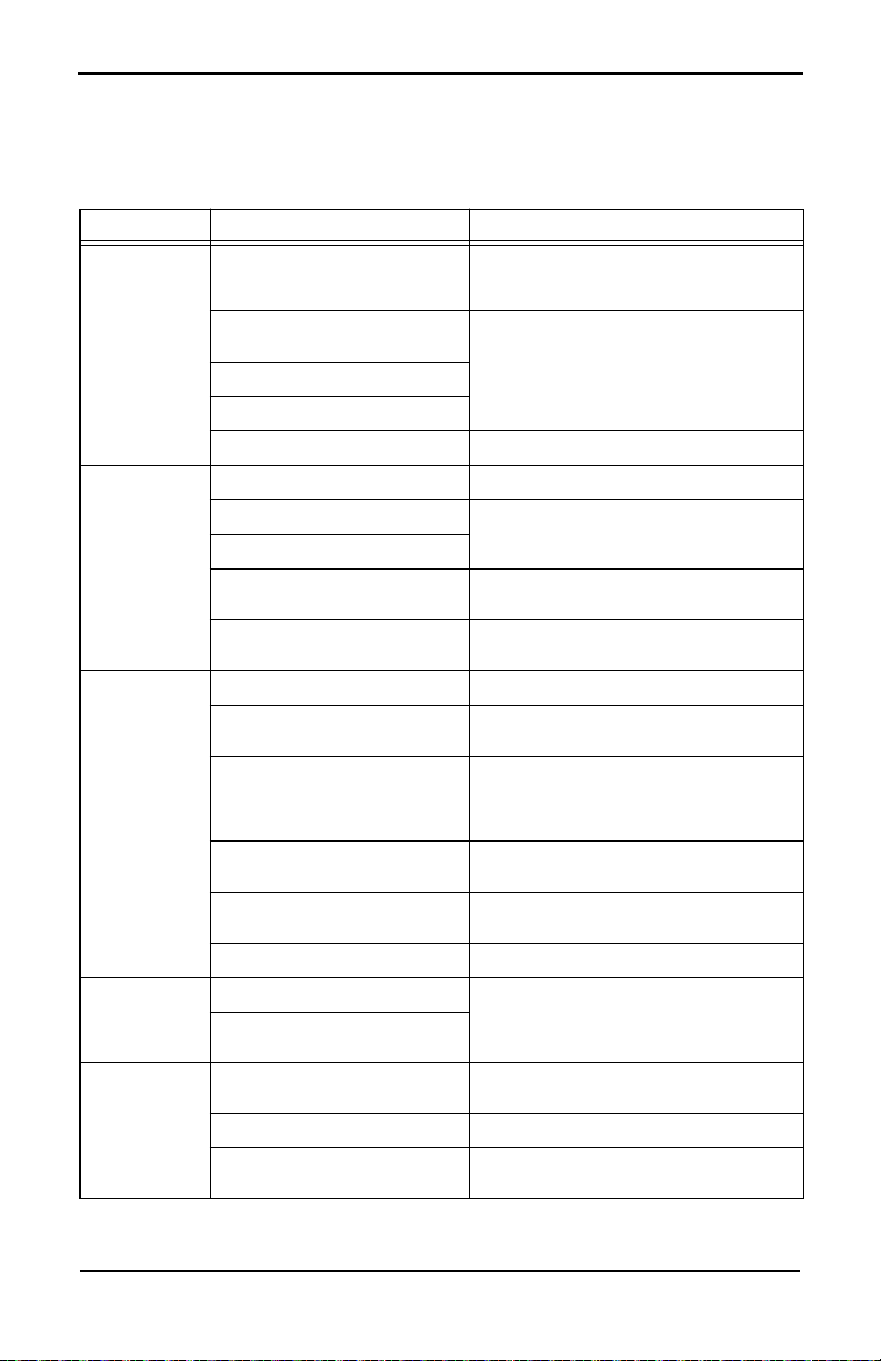
Troubleshooting / Quick Reference Guide
Owner’s Manual for 60 Hz Air-Cooled Generators 32
Section 5: Troubleshooting / Quick Reference Guide
Generator Troubleshooting
Problem Cause Correction
Engine will not
crank
Blown fuse.
Correct short circuit condition by replacing
7.5 A fuse in generator control panel. Con-
tact an IASD if fuse continues to blow.
Loose, corroded, or faulty battery
cables.
Tighten, clean, or replace as necessary.*
Faulty starter contact.
Faulty starter motor.
Discharged battery. Charge or replace battery.
Engine cranks
but will not start
No fuel. Replenish fuel / turn on fuel valve.
Faulty fuel solenoid (FS).
Contact an IASD for assistance.
Harness/wiring issue.
Faulty spark plug(s).
Inspect spark plug gap; replace spark
plug(s) if out of tolerance.
Valve clearance out of adjust-
ment, if applicable. See Engine.
Inspect and adjust valve clearance.
Engine starts
hard and runs
rough
Plugged or damaged air cleaner. Inspect and clean air cleaner.
Faulty spark plug(s).
Inspect spark plug gap; replace spark
plug(s) if out of tolerance.
Incorrect fuel pressure.
Verify fuel pressure to regulator is 10–12 in
water column (2.49–2.99 kPa) for LP gas,
and 3.5–7.0 in water column (0.87–1.74
kPa) for NG.
Fuel selector in wrong position.
Set fuel conversion valve to correct position
and program controller for fuel type.
Valve clearance out of adjust-
ment, if applicable. See Engine.
Inspect and adjust valve clearance.
Internal engine issue. Contact an IASD for assistance.
Unit is set to
OFF, but
engine contin-
ues to run
Controller wired incorrectly.
Contact an IASD for assistance.
Faulty control board.
No AC output
from generator
Generator MLCB (generator dis-
connect) is OFF (OPEN).
Set generator MLCB (generator discon-
nect) to ON (CLOSED).
Generator internal failure. Contact an IASD for assistance.
Engine may be warming up. See
Cold Smart Start.
Check the controller screen to verify status.
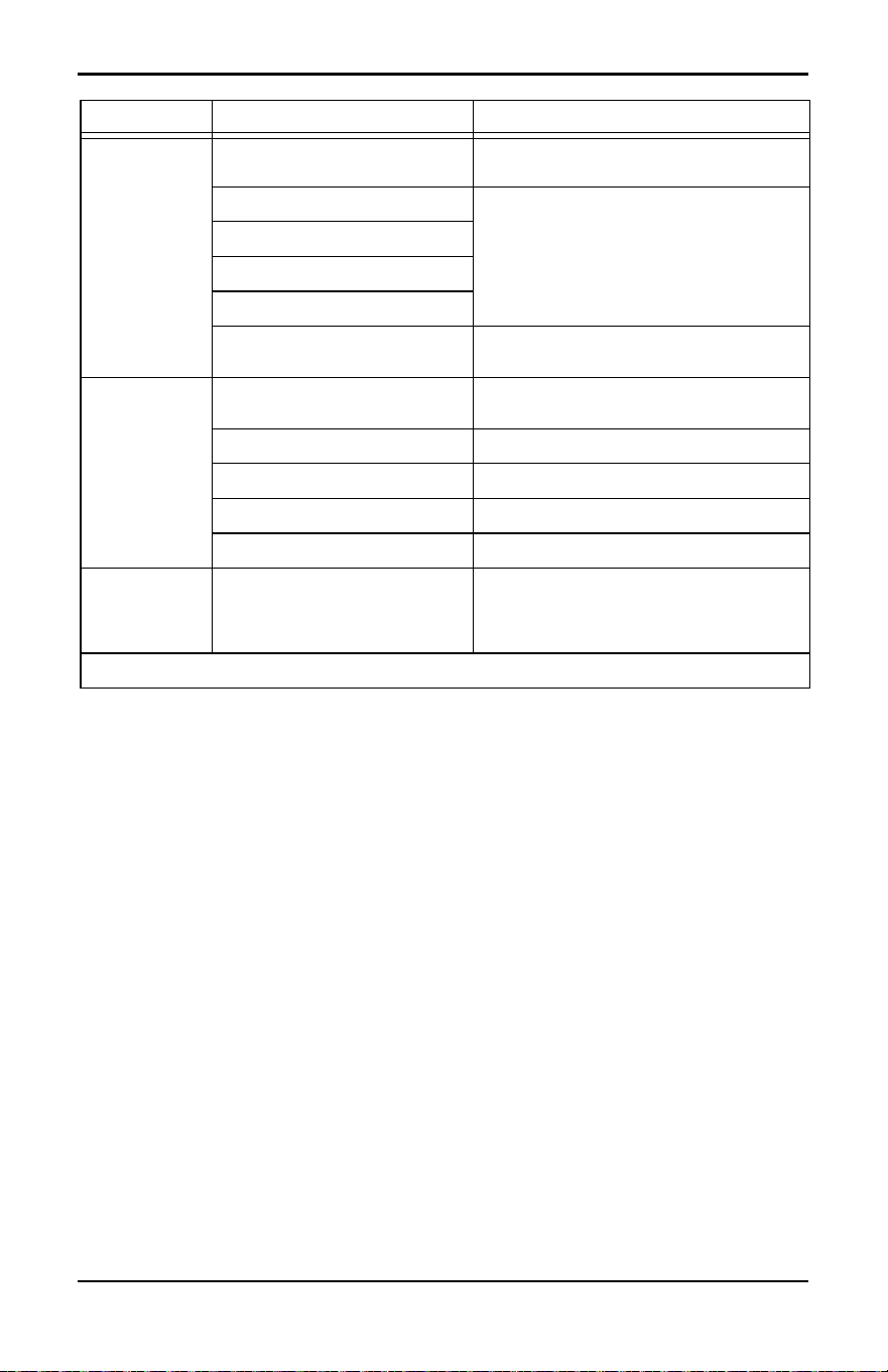
Troubleshooting / Quick Reference Guide
33 Owner’s Manual for 60 Hz Air-Cooled Generators
NOTE: IASD must have an active Tech ID and be air-cooled certified to perform any warrantable
repairs and submit warranty claims related to air-cooled products.
No transfer to
standby after
utility source
failure
Generator MLCB (generator dis-
connect) is OFF (OPEN).
Set generator MLCB (generator discon-
nect) to ON (CLOSED).
Faulty transfer switch coil.
Contact an IASD for assistance.
Faulty transfer relay.
Transfer relay circuit open.
Faulty control logic board.
Engine may be warming up. See
Cold Smart Start.
Check controller screen to verify status.
Unit consumes
large amounts
of oil
Excessive engine oil.
Adjust oil to correct level. See Checking
Engine Oil Level.
Faulty engine breather. Contact an IASD for assistance.
Incorrect type or viscosity of oil. See Engine Oil Requirements.
Damaged gasket, seal, or hose. Inspect for oil leaks.
Restricted air filter. Replace air filter.
Wi-Fi network
connection bro-
ken or intermit-
tent
Various. See Wi-Fi module owner’s manual.
* Contact an IASD or visit www.generac.com for assistance.
Problem Cause Correction
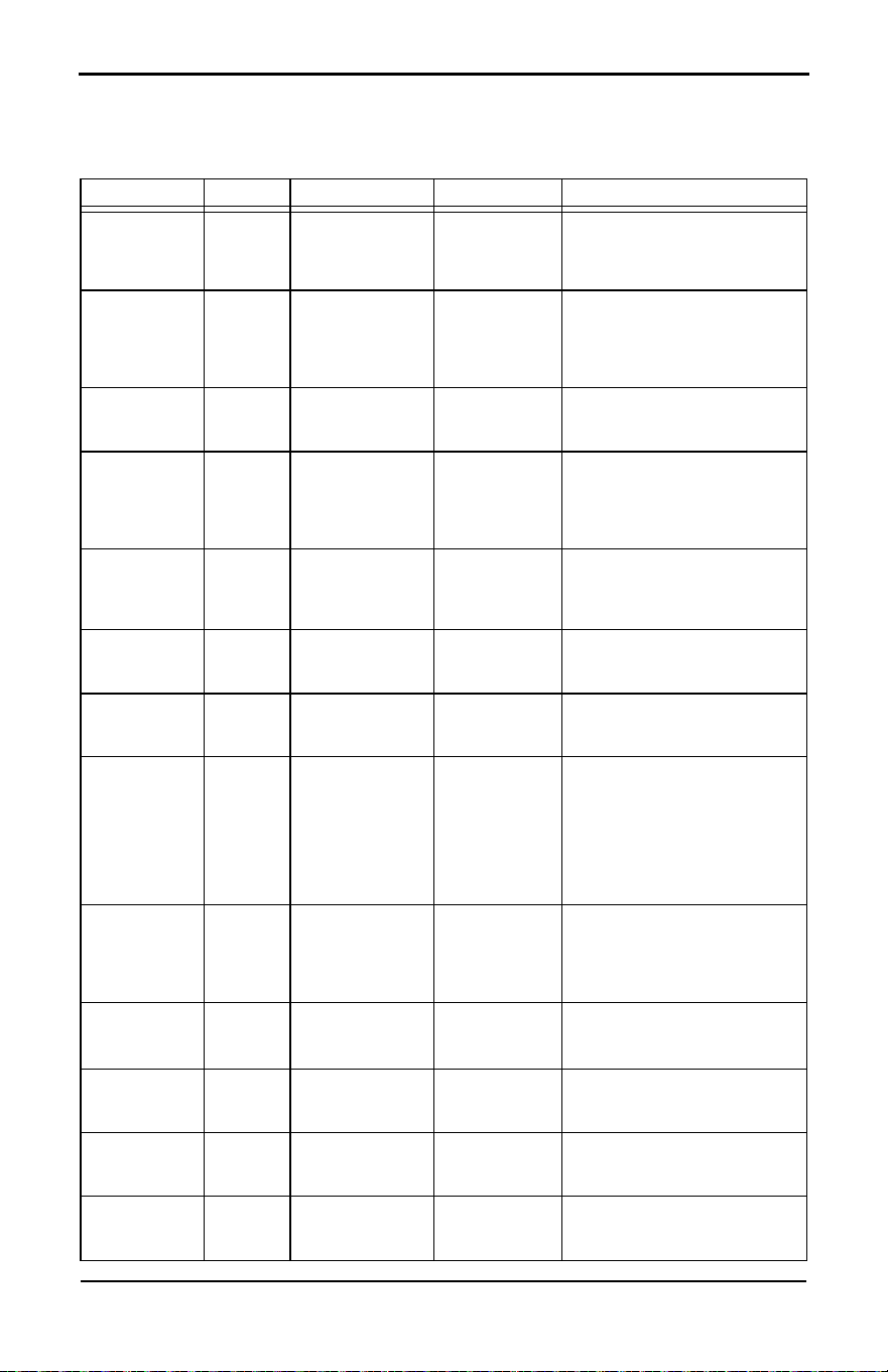
Troubleshooting / Quick Reference Guide
Owner’s Manual for 60 Hz Air-Cooled Generators 34
Quick Reference Guide
To clear an active alarm, press OFF button on the control panel, then the ENTER button, and
finally the AUTO button. Contact an air-cooled certified IASD if alarm reoccurs.
Active Alarm LED Problem Action Solution
NONE
FLASH-
ING
GREEN
Unit running in
AUTO but no
power in house.
Check genera-
tor MLCB
(generator dis-
connect).
Check generator MLCB (gen-
erator disconnect). If it is ON,
contact an IASD.
HIGH
TEMPERA-
TURE
RED
Unit shuts down
during operation.
Check LEDs /
screen for
alarms.
Inspect ventilation around gen-
erator, intake, exhaust, and
rear of generator. If no obstruc-
tions are present, contact an
IASD.
OVERLOAD
REMOVE
LOAD
RED
Unit shuts down
during operation.
Check LEDs /
screen for
alarms.
Clear alarm and remove
household loads from genera-
tor. Put in AUTO and restart.
RPM SENSE
LOSS
RED
Unit was running
and shut down,
attempts to
restart.
Check LEDs /
screen for
alarms.
Clear alarm and remove
household loads from genera-
tor. Put into AUTO and restart.
If generator does not start, con-
tact an IASD.
NOT
ACTIVATED
NONE
Unit will not start
in AUTO with util-
ity loss.
Check if
screen says
unit not acti-
vated.
See Activation section in instal-
lation manual.
NONE GREEN
Unit will not start
in AUTO with util-
ity loss.
Check screen
for start delay
countdown.
If startup delay is greater than
expected, contact an IASD to
adjust from 2 to 1500 seconds.
LOW OIL
PRESSURE
RED
Unit will not start
in AUTO with util-
ity loss.
Check LEDs /
screen for
alarms.
Check oil level and add oil as
needed. If oil level is correct,
contact an IASD.
RPM SENSE
LOSS
RED
Unit will not start
in AUTO with util-
ity loss.
Check LEDs /
screen for
alarms.
Clear alarm. Using control
panel, check battery by navi-
gating to BATTERY MENU
option from MAIN MENU. If
battery condition displays
GOOD, contact an IASD. If
control panel displays CHECK
BATTERY, replace battery.
OVERCRANK RED
Unit will not start
in AUTO with util-
ity loss.
Check LEDs /
screen for
alarms.
Verify fuel line shutoff valve is
ON. Clear alarm. Start unit in
MANUAL. If it does not start, or
starts and runs rough, contact
an IASD.
LOW VOLTS
REMOVE
LOAD
RED
Unit will not start
in AUTO with util-
ity loss.
Check LEDs /
screen for
alarms.
Clear alarm and remove
household loads from genera-
tor. Put in AUTO and restart.
OVERSPEED RED
Unit will not start
in AUTO with util-
ity loss.
Check LEDs /
screen for
alarms.
Contact an IASD.
UNDER-
VOLTAGE
RED
Unit will not start
in AUTO with util-
ity loss.
Check LEDs /
screen for
alarms.
Contact an IASD.
UNDER-
SPEED
RED
Unit will not start
in AUTO with util-
ity loss.
Check LEDs /
screen for
alarms.
Contact an IASD.
Troubleshooting / Quick Reference Guide
35 Owner’s Manual for 60 Hz Air-Cooled Generators
STEPPER
OVERCUR-
RENT
RED
Unit will not start
in AUTO with util-
ity loss.
Check LEDs /
screen for
alarms.
Contact an IASD.
WIRING
ERROR
RED
Unit will not start
in AUTO with util-
ity loss.
Check LEDs /
screen for
alarms.
Contact an IASD.
OVER-
VOLTAGE
RED
Unit will not start
in AUTO with util-
ity loss.
Check LEDs /
screen for
alarms.
Contact an IASD.
SHUTDOWN
SWITCH
FLASH-
ING RED
Unit will not start.
Check
emergency
shutdown
switches
Set emergency shutdown
switch(es) to CLOSED (I).
Clear alarm.
LOW
BATTERY
YELLOW
Yellow LED illu-
minated in any
state.
Check screen
for additional
information.
Clear alarm. Using control
panel, check battery by navi-
gating to BATTERY MENU
option from MAIN MENU. If
battery condition displays
GOOD, contact an IASD. If
control panel displays CHECK
BATTERY, replace battery.
BATTERY
PROBLEM
YELLOW
Yellow LED illu-
minated in any
state.
Check screen
for additional
information.
Contact an IASD.
CHARGER
WARNING
YELLOW
Yellow LED illu-
minated in any
state.
Check screen
for additional
information.
Contact an IASD.
CHARGER
MISSING AC
YELLOW
Yellow LED illu-
minated in any
state.
Check screen
for additional
information.
Contact an IASD.
SERVICE A YELLOW
Yellow LED illu-
minated in any
state.
Check screen
for additional
information.
Perform SERVICE A mainte-
nance. Press ENTER to clear.
SERVICE B YELLOW
Yellow LED illu-
minated in any
state.
Check screen
for additional
information.
Perform SERVICE B mainte-
nance. Press ENTER to clear.
INSPECT
BATTERY
YELLOW
Yellow LED illu-
minated in any
state.
Check screen
for additional
information.
Inspect battery. Press ENTER
to clear.
Active Alarm LED Problem Action Solution


Part No. A0001846499 Rev. C 05/12/2023
©2023 Generac Power Systems, Inc.
All rights reserved
Specifications are subject to change without notice.
No reproduction allowed in any form without prior
written consent from Generac Power Systems, Inc.
Generac Power Systems, Inc.
S45 W29290 Hwy. 59
Waukesha, WI 53189
1-888-GENERAC (1-888-436-3722)
www.generac.com