
Version number: V1.00.000
Revised date: 2022-08-30

High Level 2-Channel Lab Scope with built in Multimeter
i
MD
MAX2CSCOPE
A
WARNING
Study, understand and follow all instructions provided with this product. Read these instructions
carefully before installing, operating, servicing or repairing this tool. Keep these instructions in a safe,
accessible place.
Caution: To help prevent personal injury,
Handle device carefully. Do not drop, bend, puncture, insert foreign objects, or place heavy
objects on the device. The fragile components inside the unit may be damaged.
Connect and Disconnect Properly. Do not connect or disconnect probes or test leads while
they are connected to a voltage source.
Observe All Terminal Ratings. To avoid fire or shock hazard, observe all ratings and markings
on the product. Consult the product manual for further ratings information before making
connections to the product.
Use Proper Probe. To avoid shock hazard, use a properly rated probe for your measurement.
Avoid Circuit or Wire Exposure. Do not touch exposed connections and components when
power is on.
Do Not Operate With Suspected Failures. If suspected damage occurs with the device, have
it inspected by qualified service personnel before further operations.
Do not operate in Wet/Damp Conditions.
Do not operate in an Explosive Atmosphere.
Keep product surfaces Clean and Dry.
Do not disassemble or refit the device. The device is a sealed device and there are no
end-user serviceable parts inside. All internal repairs must be carried out by authorized
maintenance agencies or authorized technicians. Attempts to disassemble or refit the device
will void the warranty.
Do not try to replace the internal battery. The internal rechargeable battery must be replaced
by authorized maintenance agencies or authorized technicians.
AVERTISSEMENT
Étudiez, comprenez et suivez toutes les instructions fournies avec ce produit. Lisez attentivement
ces instructions avant d'installer, d'utiliser, d'entretenir ou de réparer cet outil. Conservez ces
instructions dans un endroit sûr et accessible.
Attention: pour éviter les blessures,
Manipulez l'appareil avec précaution. Ne laissez pas tomber, ne pliez pas, ne percez pas,
n'insérez pas de corps étrangers et ne placez pas d'objets lourds sur l'appareil. Les composants
fragiles à l'intérieur de l'appareil peuvent être endommagés.
Connectez et déconnectez correctement. Ne connectez ou ne déconnectez pas les sondes ou
les cordons de test lorsqu'ils sont connectés à une source de tension.
Observez toutes les valeurs nominales des bornes. Pour éviter tout risque d'incendie ou
d'électrocution, respectez toutes les caractéristiques et tous les marquages sur le produit.
High Level 2-Channel Lab Scope with built in Multimeter
ii
MD
MAX2CSCOPE
A
Consultez le manuel du produit pour plus d'informations sur les classifications avant d'effectuer
les connexions au produit.
Utilisez une sonde appropriée. Pour éviter tout risque d'électrocution, utilisez une sonde
correctement dimensionnée pour votre mesure.
Évitez l'exposition des circuits ou des fils. Ne touchez pas les connexions et les composants
exposés lorsque l'appareil est sous tension.
Ne pas utiliser avec des pannes présumées. Si des dommages suspects surviennent avec
l'appareil, faites-le inspecter par un personnel de service qualifié avant de poursuivre les
opérations.
Ne pas utiliser dans des conditions humides / humides.
N'utilisez pas l'appareil dans une atmosphère explosive.
Gardez les surfaces du produit propres et sèches.
Ne démontez pas et ne remontez pas l'appareil. L'appareil est un appareil scellé et il n'y a
aucune pièce réparable par l'utilisateur final à l'intérieur. Toutes les réparations internes doivent
être effectuées par des agences de maintenance agréées ou des techniciens agréés. Toute
tentative de démontage ou de remontage de l'appareil annulera la garantie.
N'essayez pas de remplacer la batterie interne. La batterie rechargeable interne doit être
remplacée par des agences de maintenance agréées ou des techniciens agréés.
ADVERTENCIA
Estudie, comprenda y siga todas las instrucciones proporcionadas con este producto. Lea
atentamente estas instrucciones antes de instalar, operar, dar servicio o reparar esta herramienta.
Guarde estas instrucciones en un lugar seguro y accesible.
Precaución: Para ayudar a prevenir lesiones personales,
Manipule el dispositivo con cuidado. No deje caer, doble, pinche, inserte objetos extraños ni
coloque objetos pesados en el dispositivo. Los componentes frágiles dentro de la unidad
pueden estar dañados.
Conectar y desconectar correctamente. No conecte ni desconecte sondas ni cables de
prueba mientras estén conectados a una fuente de voltaje.
Observar todas las clasificaciones de terminales. Para evitar incendios o choques, observe
todas las clasificaciones y marcas del producto. Consulte el manual del producto para obtener
más información sobre las clasificaciones antes de realizar conexiones con el producto.
Utilice la sonda adecuada. Para evitar el peligro de choque, utilice una sonda correctamente
clasificada para su medición.
Evite la exposición a circuitos o cables. No toque las conexiones y componentes expuestos
cuando la alimentación esté encendida.
No opere con errores sospechosos. Si se sospecha que se producen daños con el dispositivo,
que sea inspeccionado por personal de servicio cualificado antes de continuar con las
operaciones.
No opere en condiciones húmedas/mojadas.
No opere en una atmósfera explosiva.
High Level 2-Channel Lab Scope with built in Multimeter
iii
MD
MAX2CSCOPE
A
Mantenga las superficies del producto limpias y
secas.
No desmonte ni vuelva a ajustar el dispositivo. El dispositivo es un dispositivo sellado y no
hay piezas reparables por el usuario final en su interior. Todas las reparaciones internas deben
ser realizadas por agencias de mantenimiento autorizadas o un técnicos autorizados. Los
intentos de desmontar o reinstalar el dispositivo anularán la garantía.
No intente reemplazar la batería interna. La batería recargable interna debe ser reemplazada
por agencias de mantenimiento autorizadas o técnicos autorizados.
INTENTED USE OF THIS TOOL
This high level 2-channel lab scope with built in multimeter is designed as an add-on module, which
can work with the specific scanner of MATCO family to perform automotive oscilloscope and
multimeter functions.
Do not use this tool outside of the designed intent. Never modify the tool for any other purpose or
use.
PRODUCT INFORMATION
Made in China
to Matco specifications
FCC STATEMENT
Any Changes or modifications not expressly approved by the party responsible for compliance could
void the user’s authority to operate the equipment.
This device complies with part 15 of the FCC Rules. Operation is subject to the following two
conditions: (1) This device may not cause harmful interference, and (2) this device must accept any
interference received, including interference that may cause undesired operation.
Note: This equipment has been tested and found to comply with the limits for a Class B digital
device, pursuant to Part 15 of the FCC Rules. These limits are designed to provide reasonable
protection against harmful interference in a residential installation. This equipment generates, uses,
and can radiate radio frequency energy, and if not installed and used in accordance with the
instructions, may cause harmful interference to radio communications. However, there is no
guarantee that interference will not occur in a particular installation. If this equipment does cause
harmful interference to radio or television reception, which can be determined by turning the
equipment off and on, the user is encouraged to try to correct the interference by one or more of the
following measures:
- Reorient or relocate the receiving antenna.

High Level 2-Channel Lab Scope with built in Multimeter
iv
MD
MAX2CSCOPE
A
-
Increase the separation between the equipment and receiver.
- Connect the equipment into an outlet on a circuit different from that to which the receiver is
connected.
- Consult the dealer or an experienced radio/TV technician for help.

High Level 2-Channel Lab Scope with built in Multimeter
v
MD
MAX2CSCOPE
A
CONTENT
1 Overview ........................................................................................................................................... 1
1.1 Product Profile .............................................................................................................................. 1
1.2 Accessories Included .................................................................................................................... 1
1.3 Technical Parameters ................................................................................................................... 2
2 Component and Controls ................................................................................................................. 4
3 Operations ......................................................................................................................................... 6
3.1 Initial Use ..................................................................................................................................... 6
3.1.1 Getting Started ...................................................................................................................... 6
3.1.2 Automatic Calibration ............................................................................................................. 9
3.1.3 Connection ............................................................................................................................ 9
3.2 Operations ................................................................................................................................. 11
3.2.1 Channel Selection ................................................................................................................ 11
3.2.2 Channel Attributes & Trigger Setting .................................................................................... 11
3.2.3 Auto-Set .............................................................................................................................. 13
3.2.4 Menu Operations ................................................................................................................. 14
3.2.5 Car Test Operations ............................................................................................................. 17
3.2.6 Cursor Measurement ........................................................................................................... 17
3.2.7 Quick Save .......................................................................................................................... 18
3.2.8 REF (reference) Waveform................................................................................................... 18
4. Multimeter Operation .................................................................................................................... 19
4.1 Operation ................................................................................................................................... 19
4.1.1 Voltage Measurement.......................................................................................................... 19
4.1.2 Current Measurement.......................................................................................................... 20
4.1.3 Resistance Measurement .................................................................................................... 20
4.1.4 Diode Measurement ............................................................................................................ 21
4.1.5 Make-and-break Measurement ............................................................................................ 22
4.2 Test Example ............................................................................................................................. 22
4.3 Attention .................................................................................................................................... 23
5 Care & Maintenance ....................................................................................................................... 24

High Level 2-Channel Lab Scope with built in Multimeter
1
MD
MAX2CSCOPE
A
1 Overview
1.1 Product Profile
This MAX2CSCOPE is composed of hardware and software. Hardware includes MAX2CSCOPE module
and connection wire. The Oscilloscope and Multimeter APP are installed on diagnostic tool.
Automotive oscilloscope can make the auto repair technician to quickly judge the faults on automotive
electronic equipment and wiring, and the oscilloscope sweep speed is far greater than the signal
frequency of such vehicles, usually 5-10 times of the measured signal. The automotive oscilloscope not
only can quickly acquire the circuit signal, but also can slowly display the waveform to observe and
analyze. It can also record and store the tested signal waveform.
Multimeter is mainly used to test voltage, current and resistance. It only does simple measurements. In
this way it can determine if the device is operate normally or fault and if the circuit is complete.
1.2 Accessories Included
Common accessories are same, but for different destinations, the accessories may vary. Please consult
from the seller or check the package list supplied with this tool together.
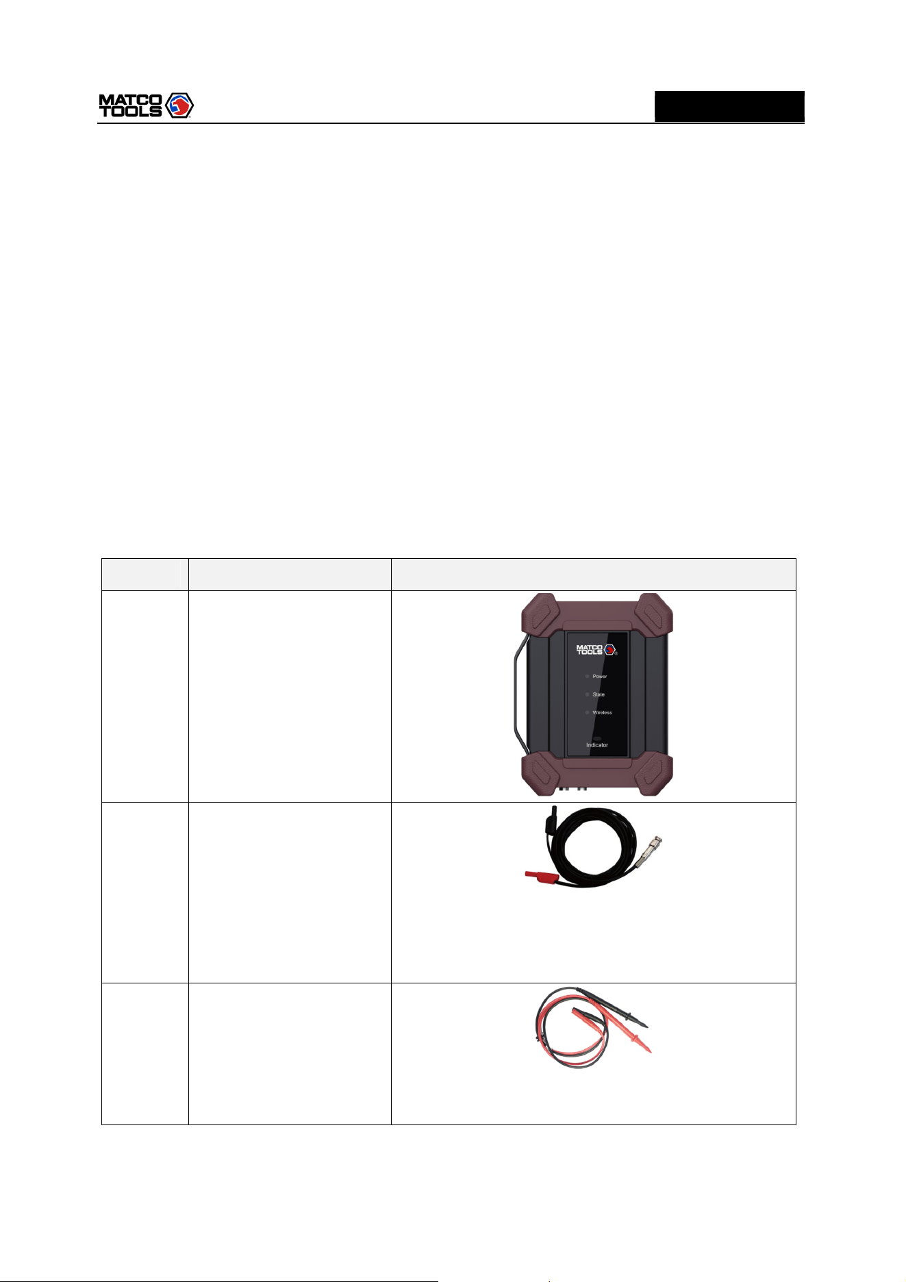
No. Name Description
1
MAX2CSCOPE
2
BNC to 4mm Test Leads
It is dedicated cable used to connect sensor and
MAX2CSCOPE and test all types of vehicle signal. If is
fitted with wide range probe, clip and hook and 4mm
connector that can plug in wire end.
3
Multimeter test pen (black
+ red)
It shall be connected to COM and V/Ω terminal of the
sensor module when using multimeter.
High Level 2-Channel Lab Scope with built in Multimeter
2
MD
MAX2CSCOPE
A
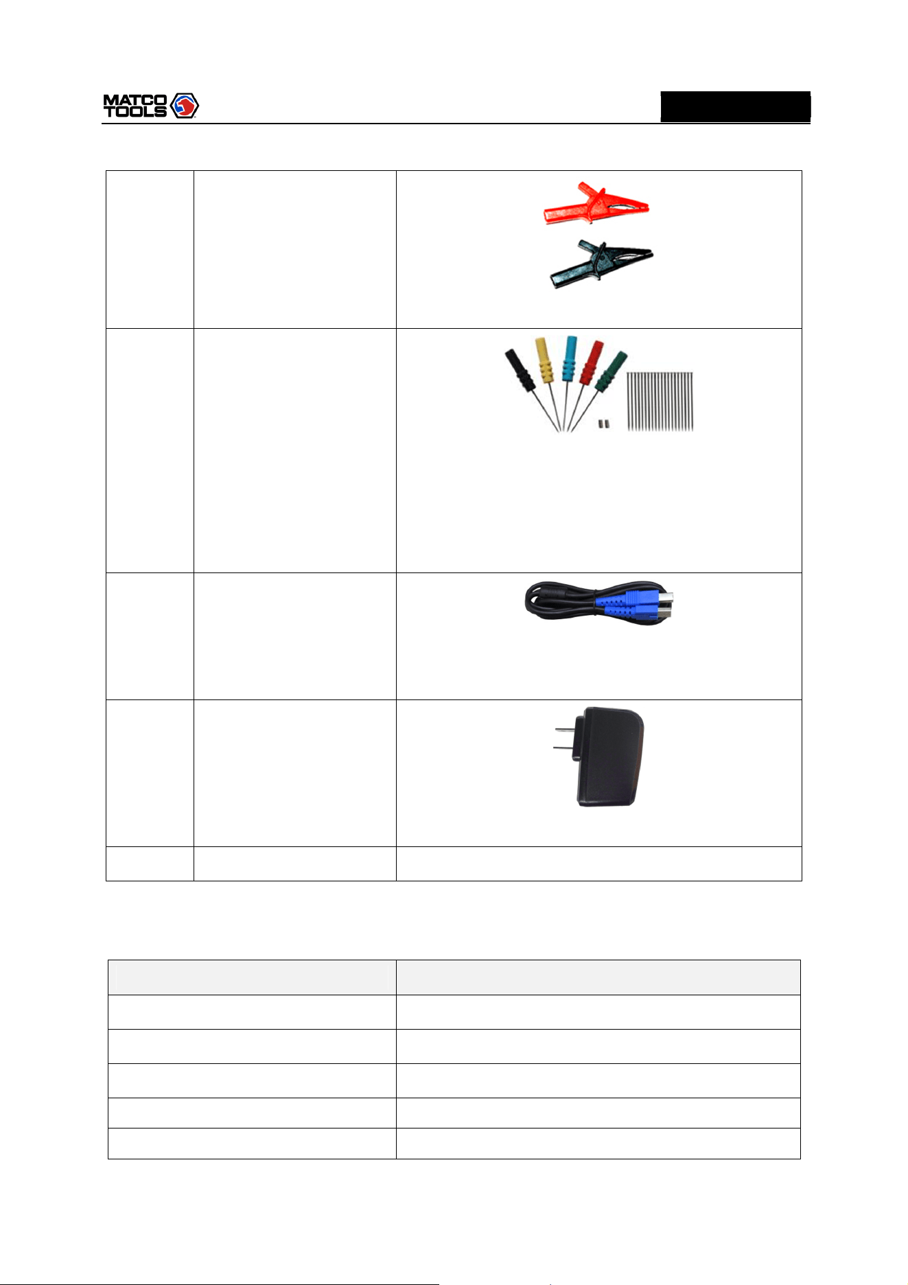
4
Crocodile Clips
Designed to connect the bare terminals or leads.
5
Back Probe Pins Suite
It can be used to connect sensor and BNC to 4mm Test
Leads, and can easily pierce the insulation of wires to
allow for automotive electrical measurements without
causing damage to the wires. Additionally, they can be
used as pin-tip probes while working with small circuit
boards.
6
Type A-Type B USB cable
Used to connect MAX2CSCOPE and diagnostic tool,
sending signal acquired by MAX2CSCOPE to diagnostics
tool to display waveform.
7
Power adapter
Charge the MAX2CSCOPE with included USB cable.
8
User manual
1.3 Technical Parameters
1. When used as Oscilloscope
Name Descriptions
Channels 2
Bandwidth 10MHz
Max. sample rate 50MHz/s
Timebase 200ns~10S
Acquisition mode Normal sampling
High Level 2-Channel Lab Scope with built in Multimeter
3
MD
MAX2CSCOPE
A
Storage depth 240KB
Coupling DC, AC
Input impedance 1MΩ±2%, 15pF±5pF parallel
Vertical sensitivity
10mV~10V x1
Vertical resolution 8bit
Max. input voltage 40V peak value (DC + AC peak value)
Probe attenuation coefficient 1X, 10X,100X (need probe support)
Trigger type Edge, Pulse width
Trigger mode Auto, Single
Auto measurement items
Peak value, average value, max value, min value,
frequency, cycle
2. When used as Multimeter
Name Descriptions
DC Voltage
Automatic range, measurement range: ±600V
AC voltage
Automatic range, measurement range: ±600V
DC current
Automatic range, measurement range: ±10A (external
sensor should be connected for large range current).
AC current
Automatic range, measurement range: ±10A. Average
value measurement (external sensor should be
connected for large range current).
Resistan
ce
Automatic range, measurement range: 0Ω~60MΩ
Diode
0.5V~2.0V
Make
-
and
-
break
detection
Make a sound when below 50Ω
High Level 2-Channel Lab Scope with built in Multimeter
4
MD
MAX2CSCOPE
A
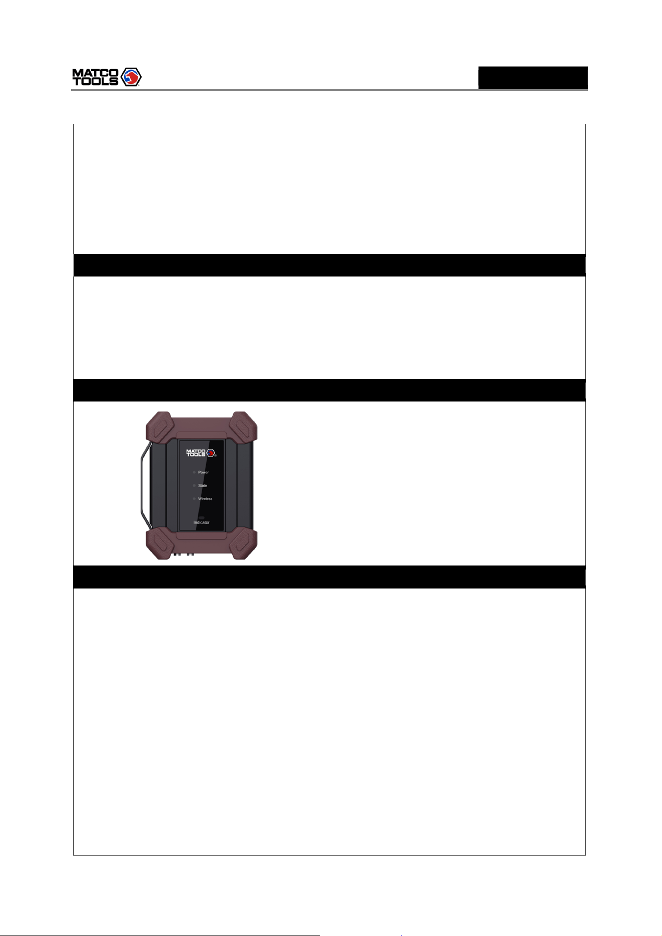
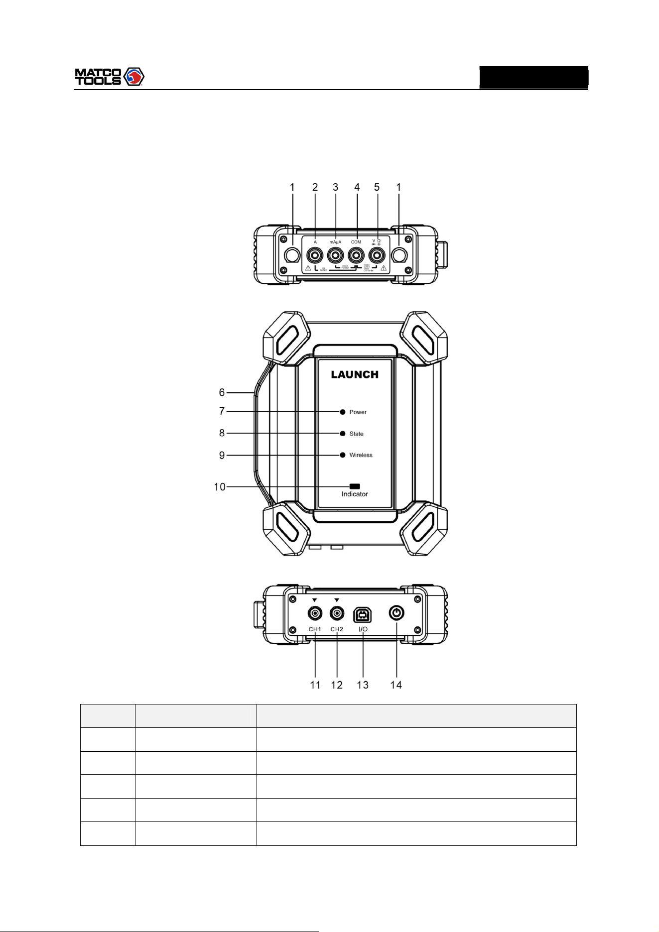
2 Component and Controls
Number
Name Description
1 Fuse
*2 A 10A current input port
*3 mAμA mA/ 400mA current input port
*4 COM Negative public port
*5
V/Ω
Voltage/resistance input terminal
High Level 2-Channel Lab Scope with built in Multimeter
5
MD
MAX2CSCOPE
A
* Note: The ports listed above are measurement ports for multimeter.
6
Handle
7 Power LED
Solid Green: Battery level normal
Sold Red: Charging.
Red Flashes: Battery level low, indicating the battery level is
below 20%.
8 State LED
Solid Green: Working normally.
Red Flashes: Working abnormally.
9 Wireless LED
Solid Green: Normally connected.
Red Flashes: Connecting in progress.
Not ON: Disconnected.
10 Indicator LED
Green Flashes: Wrong connection or poor contact.
Solid Green: Working normally.
11 CH1
Channel 1
12 CH2
Channel 2
13 I/O Port
1.
During charging, it can charge the MAX2CSCOPE with
power adapter and USB cable.
2.
During data transmission, it can connect MAX2CSCOPE and
diagnostic tool with USB cable.
Note: The diagnostic tool is not able to provide power
supply to MAX2CSCOPE. Please charge the MAX2CSCOPE
properly.
14 Power button Press it to turn on/off the MAX2CSCOPE.
High Level 2-Channel Lab Scope with built in Multimeter
6
MD
MAX2CSCOPE
A
3 Operations
3.1 Initial Use
3.1.1 Getting Started
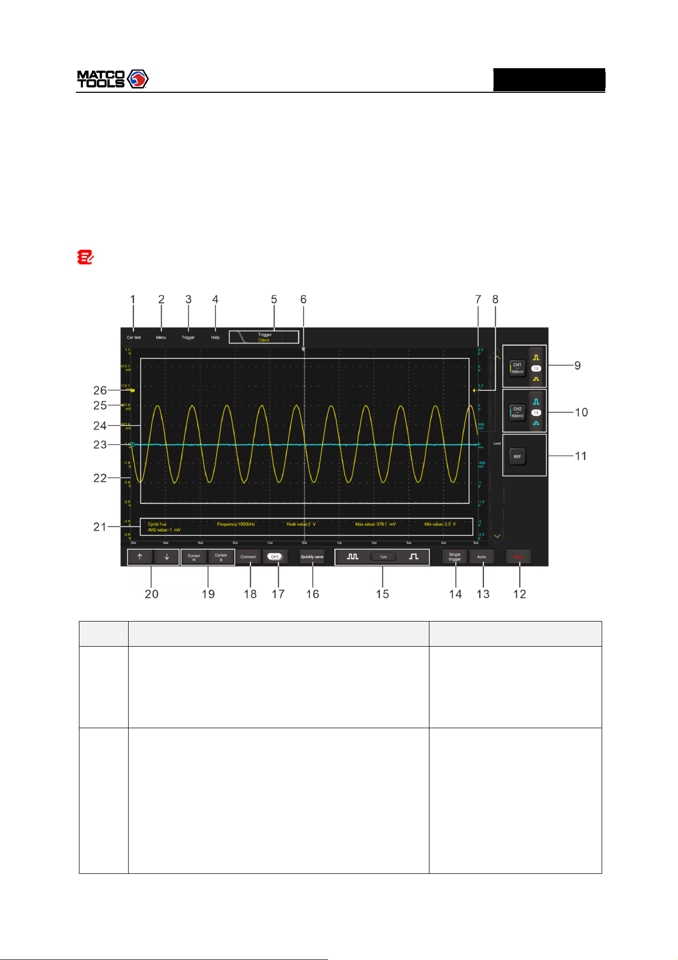
Tap the Oscilloscope app icon and the following screen will appear:
Note: If no proper connection is made, no waveforms will be displayed on the screen and most
functions become disabled.
N
o.
Description
Operation
tips
1
Car Test
Provides all kinds of the testing applications on the
automotive parts (including circuits, sensors, actuators,
ignition etc.).
Tap this button once to expand
the submenu. Tap it again to
fold the submenu.
2
Menu
Includes the following options:
•
Measure: It provides 6 parametric measurement
items.
• Save: It allows you to save format and path of channel
waveform.
•
Display: Sets the display mode of the waveform.
•
User Settings: The following items are available: clear
Tap this button once to expand
the submenu. Tap it again to
fold the submenu.
For detailed operations on the
submenus, refer to Chapter
4.4.
High Level 2-Channel Lab Scope with built in Multimeter
7
MD
MAX2CSCOPE
A
data
,
o
scilloscope settings and Automatic
calibration.
•
About: Displays the detailed information of the app.
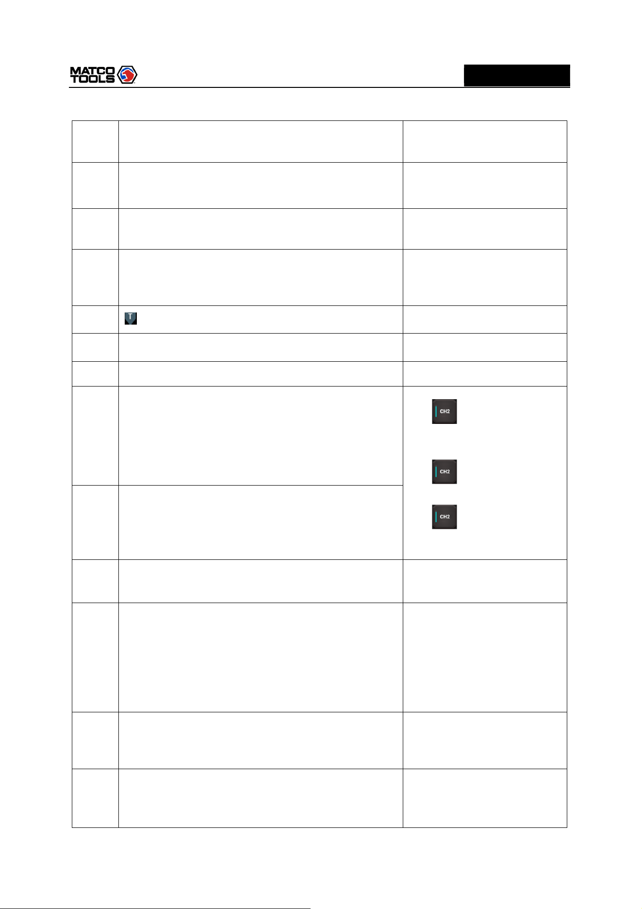
3
Trigger
It can be used to setup trigger condition and trigger type.
4
Help
Check detailed operation
instructions of application.
5
Trigger information of
current
channel
Readouts represent storage depth, sample rate and
trigger information respectively.
It shows the working status.
6
Horizontal trigger
position marker
7
Level scale of the Channel 2
8
Edge trigger level marker
9
Channel 1 vertical settings panel
Controls the amplitude of displayed signal. User can
change Invert, coupling and probe attenuation
coefficient.
Tap once - Turns on the
channel and sets it as the
current channel.
Tap twice - Calls out the
channel vertical settings.
Tap three times - Turns
off the channel.
10
Channel 2 vertical settings panel
Controls the amplitude of displayed signal. User can
change Invert, coupling and probe attenuation
coefficient.
11
Reference channel
settings panel
Setup reference channel.
12
RUN/STOP/WAIT
WAIT: All pre-triggered data has been acquired and
the MAX2CSCOPE is ready to accept a trigger.
STOP: The MAX2CSCOPE has stopped acquiring
waveform data.
RUN: The MAX2CSCOPE is running.
13
Auto
It automatically adjusts the vertical scale, horizontal scale
and trigger settings.
Tap this button to start auto
setup function.
14
Single trigger
Capture one single trigger, complete acquisition, and
then stop.
High Level 2-Channel Lab Scope with built in Multimeter
8
MD
MAX2CSCOPE
A
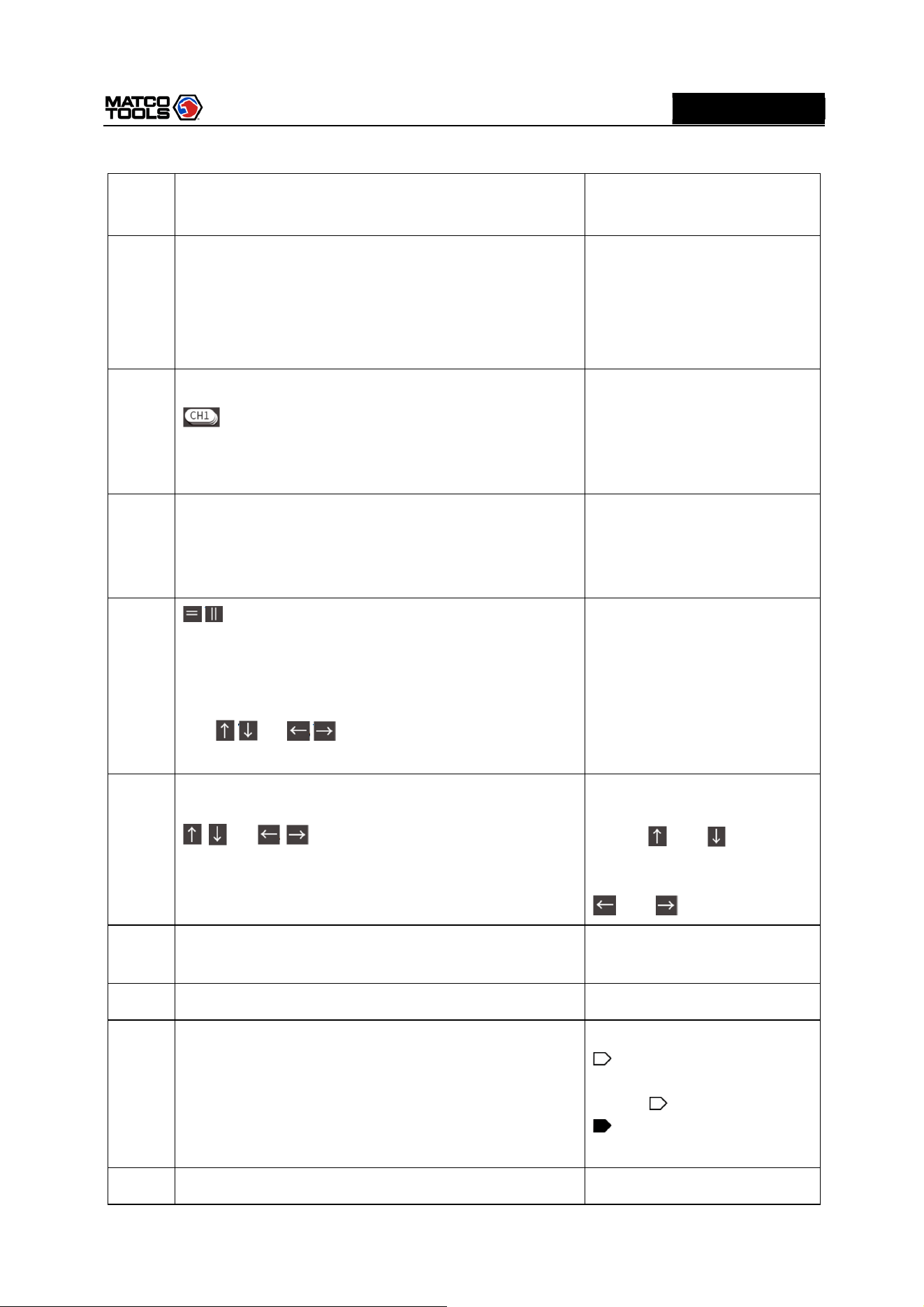
15
Horizontal
s
etting
Control the time base.
16
Quick save
Quickly saves the measured waveform of current
channel.
To modify save path and file type, please go into Menu
-> Save.
17
Channel selection button
Tap it to select the target channel.
Tap this button once, the
channel (only the channels that
have been turned on) selection
pop-up will appear. Tap it again
to fold the submenu.
18
Connection status button
Tap
th
is
button to search and
connect MAX2CSCOPE. It will
display “Connected” when
successfully connected.
19
/
Cursor position
Turn on/off the horizontal/vertical cursor measurement
function. When set to ON, two horizontal/vertical
reference lines named with Y1 & Y2/X1 & X2 will be
displayed on the waveform display area. The user can
use / or / to fine tune the line or drag the
line directly to move it.
Tap this button once to start
the cursor calculation function.
Tap it again to disable it.
20
/ or / Fine-tuning button
Fine tunes the vertical/horizontal reference line.
When the horizontal cursor is
ON, the fine tuning buttons
display and . If the
vertical cursor is ON, the fine
tuning buttons will change into
and .
21
Measurement value area
Go
to
Menu
-
>
Measure
to
expand it.
2
2
Level scale of the Channel 1
23
Channel 2 marker
Shows the reference points of the displayed waveforms.
If there is no marker, the channel is not displayed.
If the marker is displayed as
, it indicates the channel is
not the current channel. Tap the
marker , it will change into
; it indicates the channel is
the current channel.
2
4
Waveform display area
High Level 2-Channel Lab Scope with built in Multimeter
9
MD
MAX2CSCOPE
A
25
Channel 1 marker
Shows the reference points of the displayed waveforms.
If there is no marker, the channel is not displayed.
Same with “Channel 2
marker”.
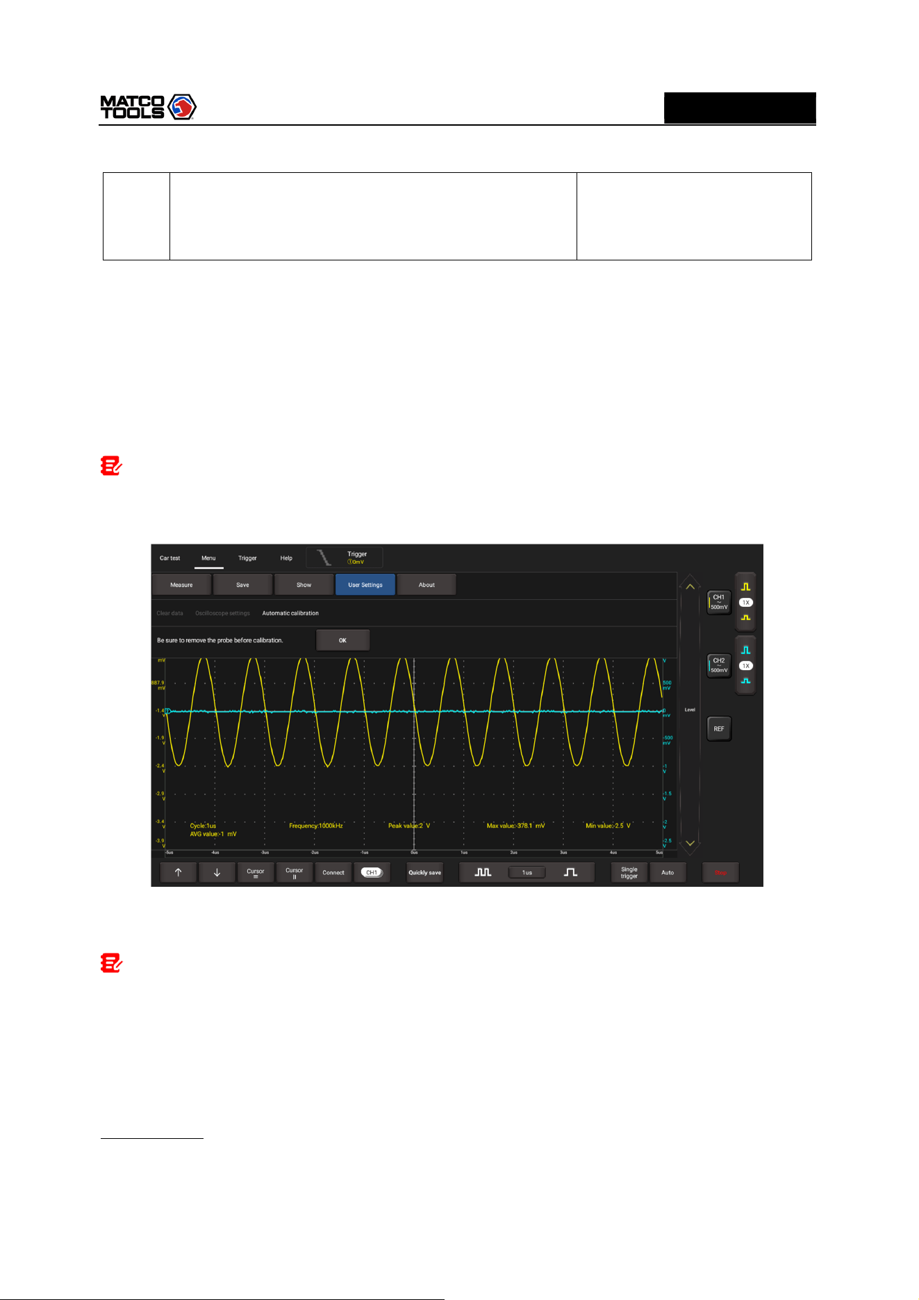
3.1.2 Automatic Calibration
The automatic calibration routine lets you optimize the oscilloscope signal path for maximum
measurement accuracy. You can run the routine at any time but you should always run the routine if the
ambient temperature changes by 10°C or more.
For accurate calibration, power on the MAX2CSCOPE and wait twenty minutes to ensure it is warmed
up. Calibration mainly includes simulation channel calibration, trigger voltage of trigger circuit calibration
and non-linear calibration of horizontal base line deviation.
Note
:
During auto calibration, please make sure no signal in input terminal of CH1 / CH2, otherwise it
may damage device.
Tap Menu -> User Settings, then tap Automatic Calibration.
Tap OK on the pop-up message box to start calibration. The LED on the MAX2CSCOPE starts flashing
and the prompt message “Calibrating, please wait” will appear on the upper left corner of the screen.
Note: While calibrating, no operations are allowed to perform until the calibration process is
successfully finished.
The self-calibration routine takes several minutes. After calibration is complete, the prompt message
“Correction successful” will pop up on the screen.
Tap OK to complete automatic calibration.
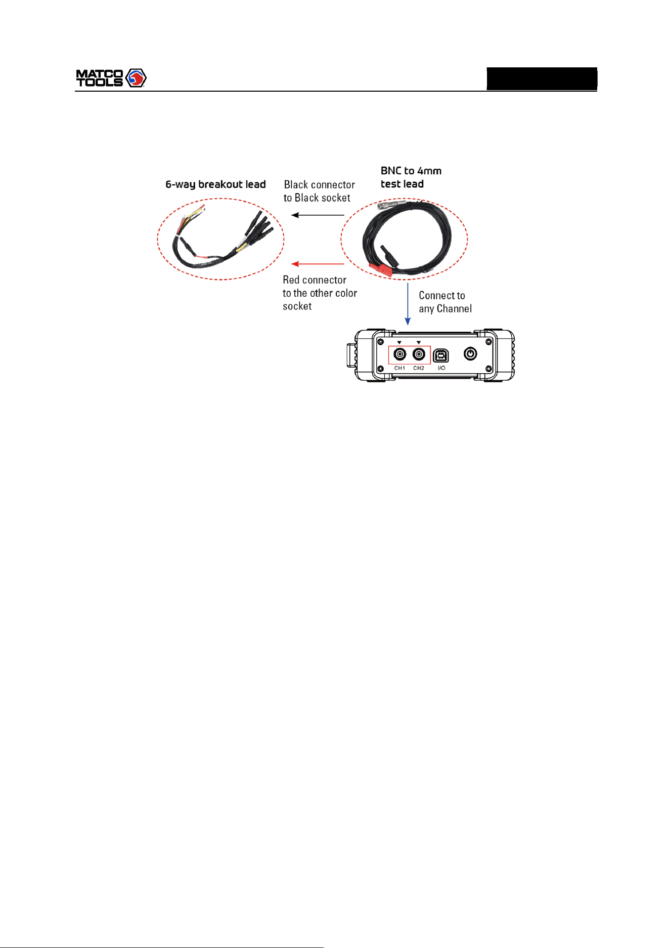
3.1.3 Connection
Testing Sensor:
1.
Connect the BNC connector of the BNC to 4mm test lead to the CH1/CH2 (select number of channel
and channel No. according to actual situations), and plug the black (GND) and red (SIGNAL) 4mm
High Level 2-Channel Lab Scope with built in Multimeter
10
MD
MAX2CSCOPE
A
connectors into the Black (GND) and other color (SIGNAL) banana sockets of the 6-way breakout leads
(optional) respectively.
2.
Connect the black terminal and signal wire (its other end connected to the red 4mm connector) of the
6-way breakout lead to the GND and signal terminal of the vehicle sensor.
High Level 2-Channel Lab Scope with built in Multimeter
11
MD
MAX2CSCOPE
A
3.2 Operations
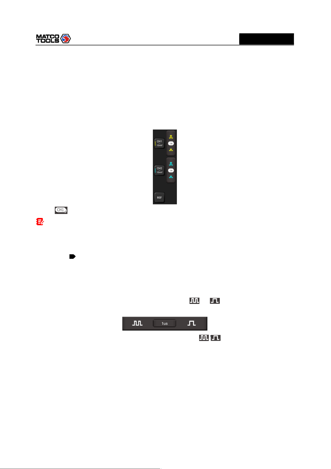
3.2.1 Channel Selection
A total of 3 channels are available: CH1, CH2 and REF (reference channel). Follow the methods to select
a channel:
There are two methods for you opt:
A. Tap the channel tab shown on the right edge of the screen.
B. Tap to select the target channel. This method is only applicable to the channel that is turned on.
Note: For better comparison and identification, each channel and waveform is marked in
different color.
The MAX2CSCOPE can display multiple waveforms simultaneously, but only one waveform is allowed
to display at top. The top channel is called current channel. The marker of the current channel is
displayed as , otherwise it is non-current channel.
3.2.2 Channel Attributes & Trigger Setting
Channel attributes can be set via horizontal settings and vertical settings.
1. Horizontal Settings
User can change the horizontal time/division scale by tapping or directly or by tapping the
time/division value to select it from the pull-down list.
If the waveform acquisition is stopped, the time/division selector ( / ) expands or compresses the
waveform.
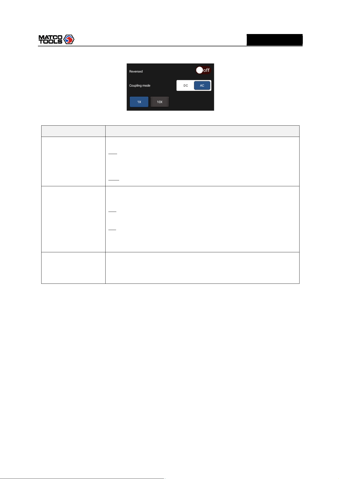
2. Vertical Setup
This option allows you to adjust vertical scale and position, and other channel setup. Each channel has
one separate vertical menu, you can set it individually.
Tap the target channel to call out the vertical setting option.
High Level 2-Channel Lab Scope with built in Multimeter
12
MD
MAX2CSCOPE
A
Option descriptions:
Menu
Comments
/
Settings
Reversed
This option
will affect how channel is displayed.
ON: Turn on the invert function. When Invert is set as On, voltage value of
displayed wave is reversed (upside down). When using basic trigger, it is
necessary to adjust the trigger level to keep waveform triggered steadily.
OFF: Restore to the original display of the waveform.
Coupling mode
Trigger coupling
determines what part of the signal passes to the trigger
circuit. AC and DC are included:
DC: Both DC and AC current can pass through, and can be used to view
waveform as low as 0Hz without large DC offset.
AC: The DC signal of the tested signal is blocked, and only AC current is
allowed to pass through, and can be used to view waveform with large DC
offset.
Probe type
Choose the
probe attenuation coefficient
Attenuation coefficient changes the vertical ratio of MAX2CSCOPE so that
the measurement results reflect the true voltage at the probe.
3. Trigger setting
The trigger determines when the Oscilloscope starts to acquire data and display a waveform. When a
trigger is set up properly, it can convert unstable displays or blank screens into meaningful waveforms.
When the Oscilloscope starts to acquire a waveform, it collects enough data so that it can draw the
waveform to the left of the trigger point. The Oscilloscope continues to acquire data while waiting for the
trigger condition to occur. After it detects a trigger, the Oscilloscope continues to acquire enough data so
that it can draw the waveform to the right of the trigger point.
Trigger indicates that when certain waveform meets the conditions that are predefined according to the
requirements, the Oscilloscope acquires the waveform and its adjacent section, and then presents it on
the screen.
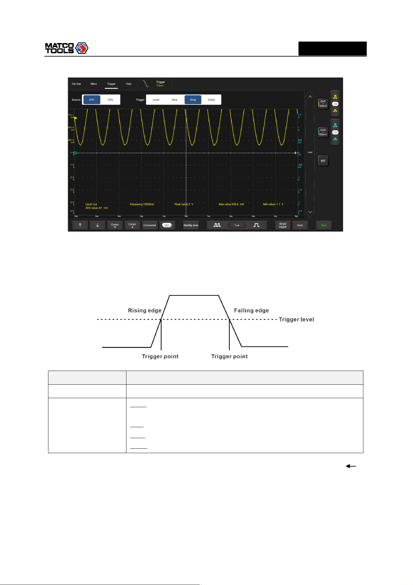
Go to Trigger, the following screen will appear:
High Level 2-Channel Lab Scope with built in Multimeter
13
MD
MAX2CSCOPE
A
The MAX2CSCOPE applies edge trigger, which is the most commonly used and effective trigger method.
A clear majority of applications apply this trigger method to trigger waveform. An edge trigger
determines whether the Oscilloscope finds the trigger point on the rising/falling/dual edge of a signal.
When tested signal voltage direction is consistent with preset direction, and value reaches trigger
voltage, the MAX2CSCOPE will be triggered and capture waveform.
Menu
Comments/Settings
Source
Select channel source of
triggered signal.
Trigger
Level
: The electrical level that signals shall exceed when capturing
waveform.
Rise: Trigger on rising edge.
Drop: Trigger on falling edge.
Close: Turning off trigger mode.
In this mode, the user can set the trigger level by directly dragging the Level scroll bar or the icon on
the right side of the waveform display area.
3.2.3 Auto-Set
The Oscilloscope has an Auto-set feature that sets up the Oscilloscope automatically to display the input
signal in a best fit.
Tap Auto, the MAX2CSCOPE may change the current settings to display the signal. It automatically
High Level 2-Channel Lab Scope with built in Multimeter
14
MD
MAX2CSCOPE
A
adjusts the vertical and horizontal scaling, as well as the trigger coupling and position.
3.2.4 Menu Operations
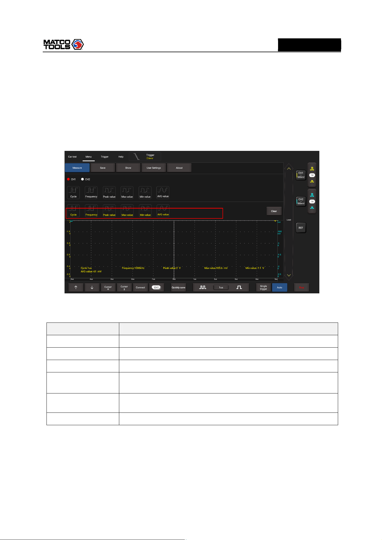
1. Measure
The MAX2CSCOPE provides 6 parametric auto measurements. Tap Measure, the following screen will
appear:
Tap to select the desired measurement item. All selected items will be shown on the left side of the
Clear button.
Tap it to remove the measurement item. The values corresponding to the selected items will be
displayed on the bottom of the screen.
Parameter type
Description
Cycle
Time for the first signal cycle to complete in the waveform.
Frequency
Reciprocal of the period of the first cycle in the waveform.
P
eak
v
alue
Peak
-
to
-
peak = Max
-
Min,
measured over the entire waveform.
Max value
Voltage of the absolute maximum level, measured over the entire
waveform.
Min value
Voltage of the absolute minimum level, measured over the entire
waveform.
AVG
v
alue
The arithmetic mean over the entire
waveform.
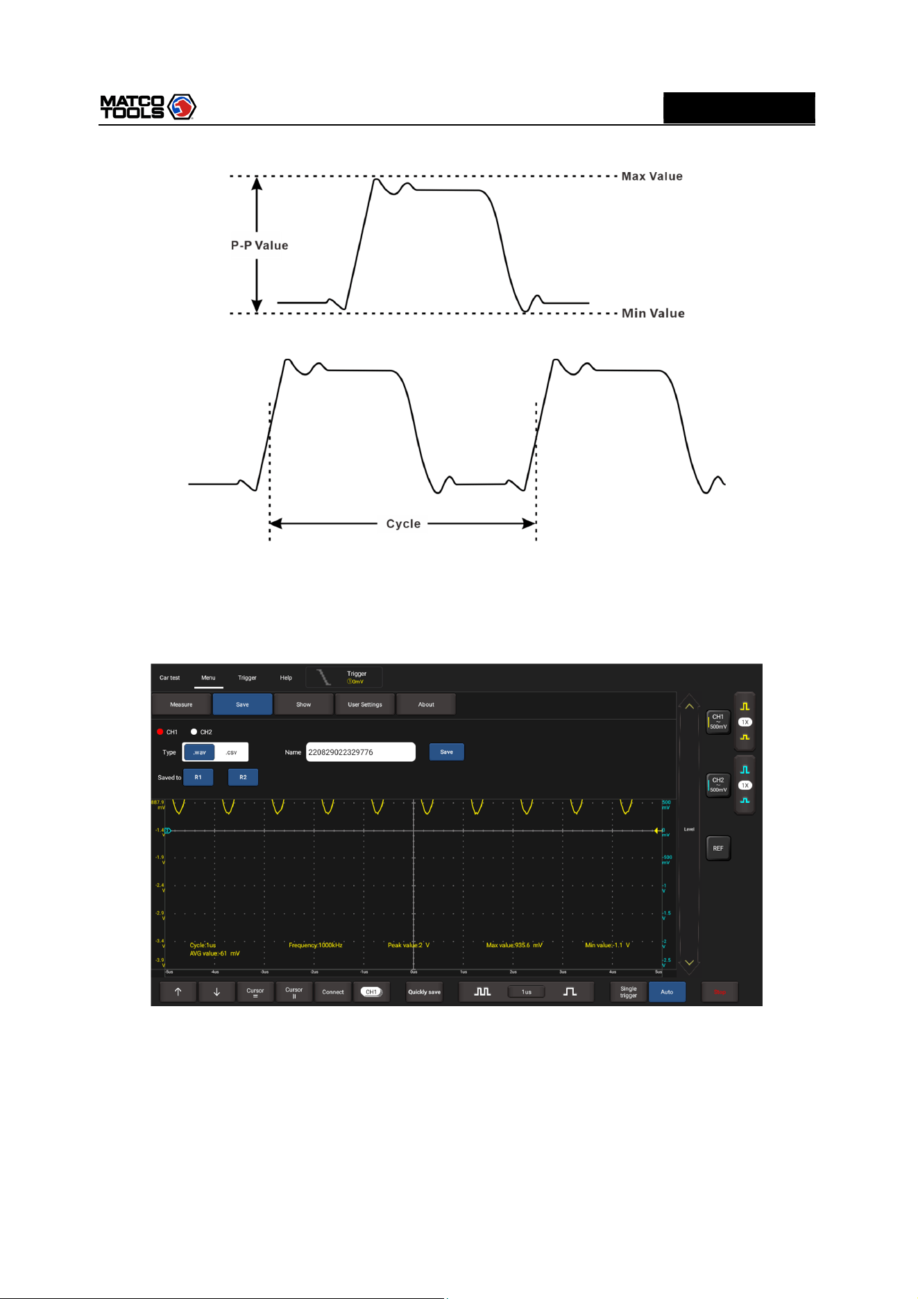
The following illustrations explain some common measurement items for your reference.
High Level 2-Channel Lab Scope with built in Multimeter
15
MD
MAX2CSCOPE
A
Tap Clear to turn off all measurement items.
2. Save
This function allows you to save the waveforms of the channels.
Tap Save, the following screen will appear:
Select the desired measurement channel and save type (.WAV or .CSV), tap the default file name to
revise it. Tap Save to save it. Alternatively, the user can save the waveform files to the designated folder
(R1, R2). If the files are saved under the folder, the user can recall the saved files for reference and play
back through REF channel.
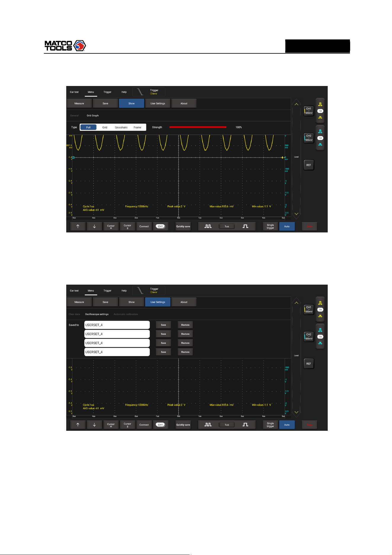
3. Display
This function enables you to setup waveform brightness, coordinate axis display level. Coordinate axis
comes with Full, Grid, Crosshairs and Frame.
High Level 2-Channel Lab Scope with built in Multimeter
16
MD
MAX2CSCOPE
A
Tap Display, the following screen will appear:
4. User Settings
This option can set data clearing, waveform display auto calibration and oscilloscope parameter save and
recovery.
Tap User Settings, the following screen will appear:
Item description:
Clear Data: Clear saved data and user setup.
Oscilloscope settings: User can save system setup parameter using Save function. Restore function
can enable user to use system setup saved previously so as to avoid repeated setup.
Automatic calibration: The self-calibration routine lets you optimize the oscilloscope signal path for
maximum measurement accuracy. Refer to Chapter 3.1.2 for detailed operations.
5. About
High Level 2-Channel Lab Scope with built in Multimeter
17
MD
MAX2CSCOPE
A
Displays basic information of the APP.
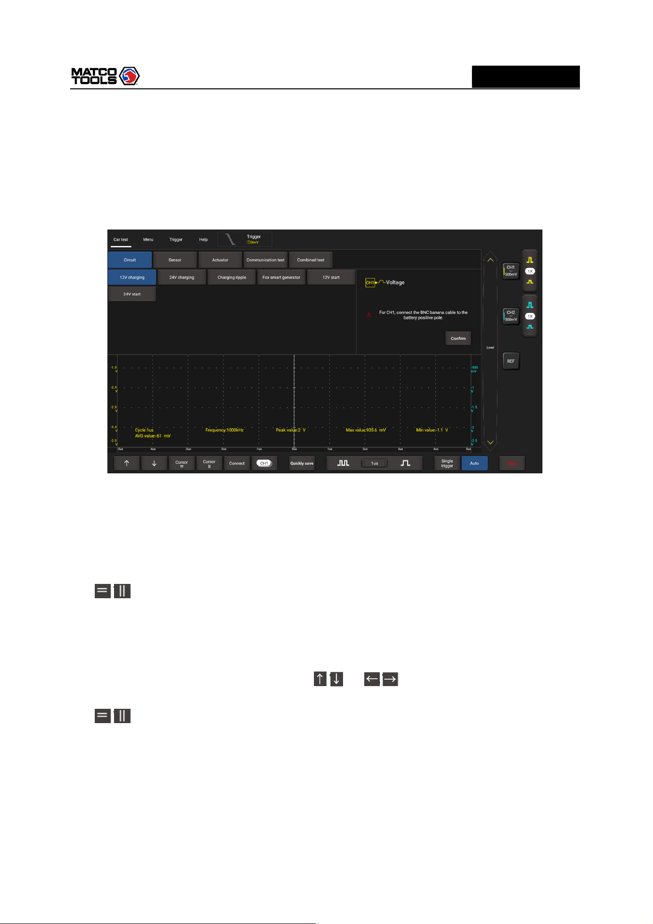
3.2.5 Car Test Operations
This function provides all kinds of the testing applications on the automotive parts (including circuits,
sensors, actuators, ignition etc.) and detailed connection methods.
Tap Car test, the following screen will appear:
Tap to select the desired automotive part, the system will automatically configure the option to the
preset parameters. The user does not need to make any settings. Just follow the on-screen instructions
to make connections and proceed.
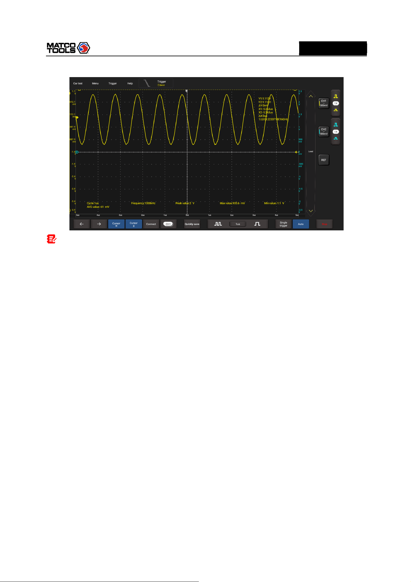
3.2.6 Cursor Measurement
The Cursor function can be used for assisting in measurement.
Tap / to turn on the cursor function and place the cursor on the measurement point to read the
waveform measurement value.
There are two types of cursors: horizontal cursor and vertical cursor. The horizontal cursor measures the
value in the vertical direction, and the vertical cursor can measure the value in the horizontal direction.
When set to ON, two horizontal/vertical reference lines named with Y1 & Y2/X1 & X2 will be displayed
on the waveform display area. The user can use / or / to fine tune the line or drag the line
directly to move it.
Tap / again to turn it off.
High Level 2-Channel Lab Scope with built in Multimeter
18
MD
MAX2CSCOPE
A
Note:
△Reading: indicates the difference between the two cursor positions.
The voltage reading after Y1, Y2: indicates the position of the activated cursor in the horizontal cursor
relative to the zero level.
The time reading after X1, X2: indicates the position of the activated cursor in the vertical cursor relative
to the trigger point.
1/△X: Frequency.
3.2.7 Quick Save
This function is used to quickly save the currently running measurement waveform. The MAX2CSCOPE
can save waveform of analog channel or mathematical channel to the local. Saved file format can be
WAV or CSV.
MAX2CSCOPE has two reference channels. WAV file can be uploaded to reference channel for
waveform reference. Relevant setup can be found in “Menu”.
3.2.8 REF (reference) Waveform
MAX2CSCOPE has reference channel to display reference waveform. User can upload previously
saved WAV file to reference channel and compare it with actual waveform so as to identify difference.
High Level 2-Channel Lab Scope with built in Multimeter
19
MD
MAX2CSCOPE
A
4. Multimeter Operation
Multimeter is mainly used to test voltage, current, resistance, diode and Make-and-break. It only does
simple measurements. In this way it can determine if the device is operate normally or fault and if the
circuit is complete.
4.1 Operation
1. First connect the MAX2CSCOPE to power supply.
2. Connection method varies with tested object. Please refer to the following method to test:
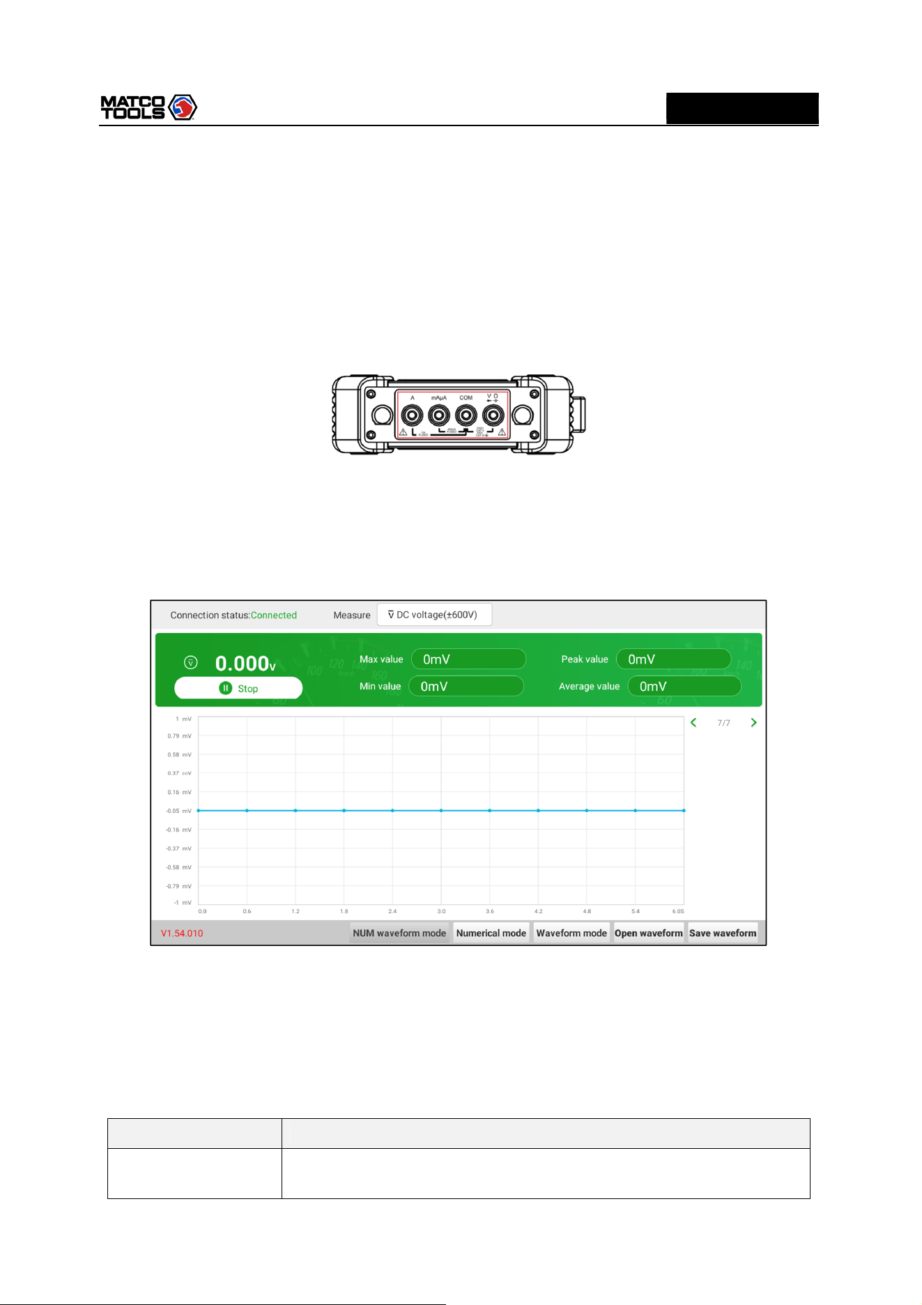
4.1.1 Voltage Measurement
DC voltage and AC voltage measurement apply the same connection method.
1.
Tap Toolbox -> Multimeter on the diagnostic tool to enter the following screen.
2.
Select DC voltage/AC voltage and corresponding range, tap Not connected to search for
MAX2CSCOPE. When it is successfully connected, the diagnostic tool will display connection status.
3.
Insert one end of black test pen into COM terminal of MAX2CSCOPE, insert one end of red test pen
into V/Ω terminal of MAX2CSCOPE.
4.
Attach black and red test pen tip to tested point. Keep test pen attached to it firmly.
Option descriptions:
Menu
Comments/Settings
Numerical waveform
mode
Displays the measurement result in both numerical and waveform form.
High Level 2-Channel Lab Scope with built in Multimeter
20
MD
MAX2CSCOPE
A
Numerical mode
Displays the
measurement result in
numerical form
.
Waveform mode
Displays the
measurement result in
waveform form
.
Open waveform
O
pen saved waveform file
.
Save waveform
Save
measurement result as
a
waveform file
.
5.
Tap Start, numerical value will be displayed directly on the diagnostic tool.
Warning: the tip of the test pen is metal, do not touch it with hands during measurement, otherwise it
might cause electricity shock and affect measurement results.
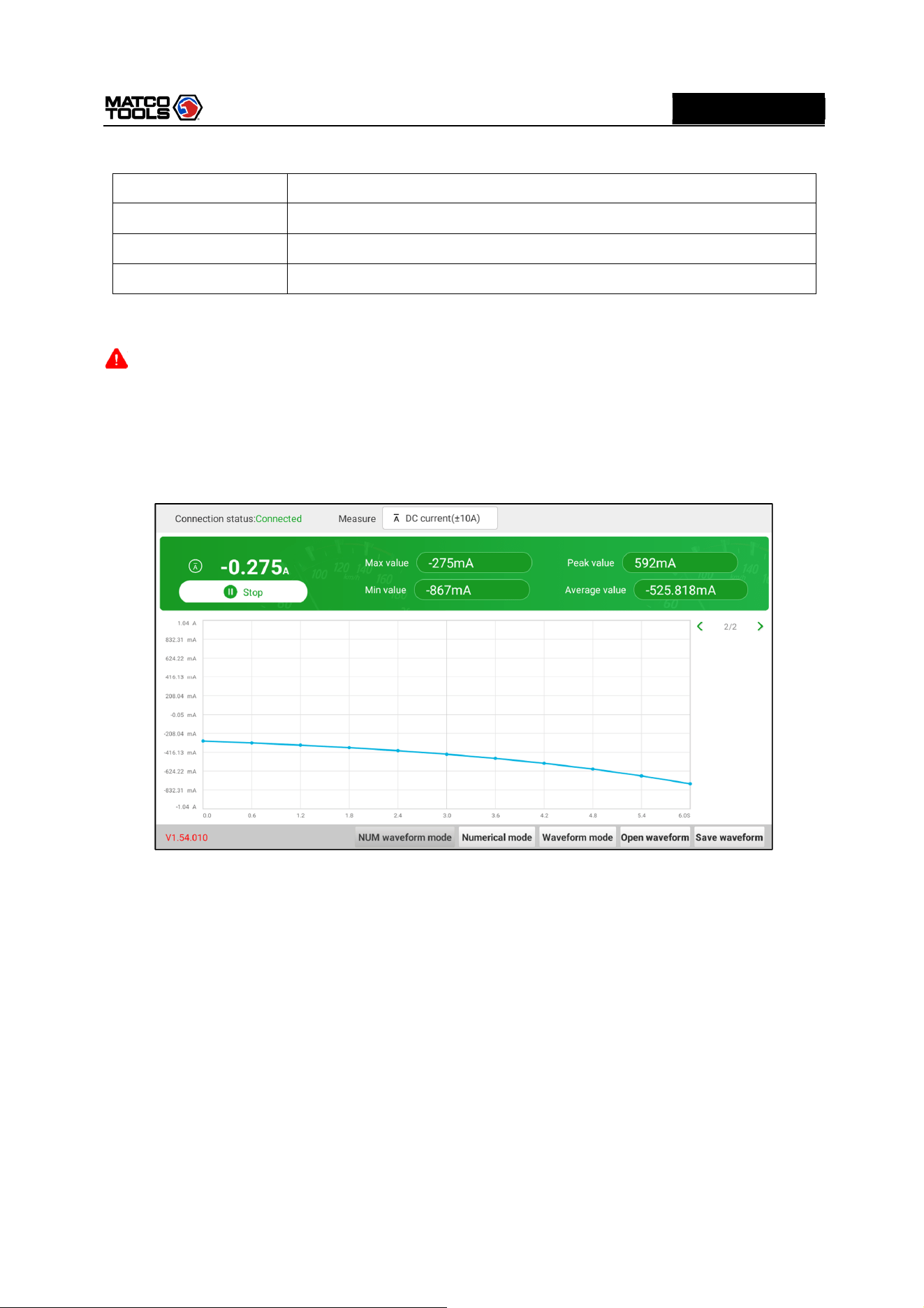
4.1.2 Current Measurement
DC current and AC current measurement apply the same connection method.
1.
Tap Toolbox -> Multimeter on the diagnostic tool to enter the following screen.
2.
Select DC current/AC current and corresponding range, tap Not connected to search for
MAX2CSCOPE. When it is successfully connected, the diagnostic tool will display connection status.
3.
Insert black test pen into COM terminal of MAX2CSCOPE. If measured current is above 400mA,
insert red test pen into A terminal of MAX2CSCOPE. If measured current is below 400mA, insert red
test pen into mAμA terminal of MAX2CSCOPE.
4.
Connect black and red test pen to tested point. Keep test pen attached to it firmly.
5.
Tap “Start”, numerical value will be displayed directly on diagnostic tool.
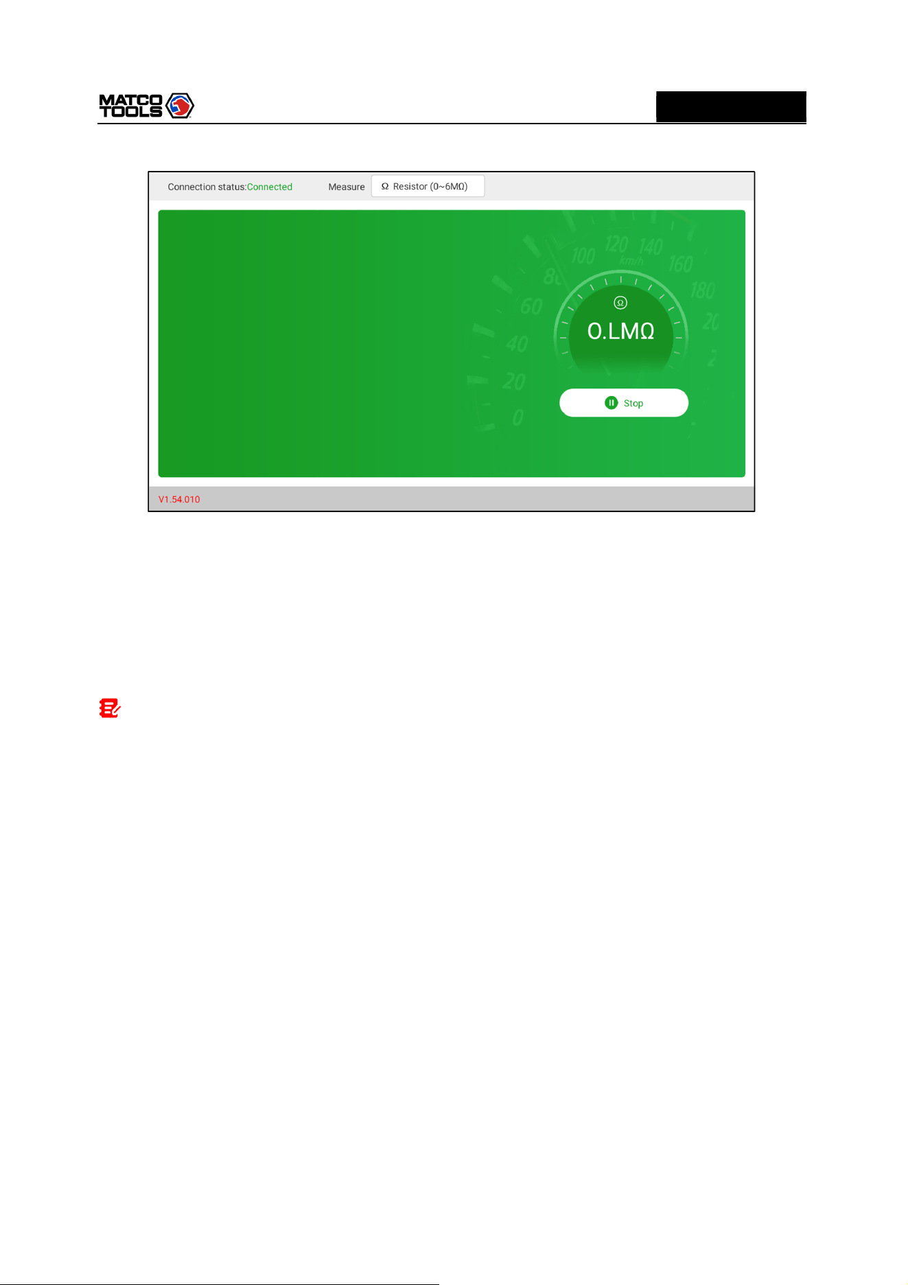
4.1.3 Resistance Measurement
1.
Tap Toolbox -> Multimeter on the diagnostic tool to enter the following screen.
High Level 2-Channel Lab Scope with built in Multimeter
21
MD
MAX2CSCOPE
A
2.
Select Resistance, tap Not connected to search for MAX2CSCOPE. When it is successfully
connected, the diagnostic tool will display connection status.
3.
Insert black test pen into COM terminal of MAX2CSCOPE, insert red test pen into V/Ω terminal of
MAX2CSCOPE.
4.
Attach black and red test pen to metal part of resistance ends. Keep test pen firmly attached to
resistance.
5.
Numerical value will be displayed directly on the diagnostic tool.
Note: you can touch resistance with hands during measurement, but do not touch both ends of
resistance simultaneously, as it will affect measurement accuracy.
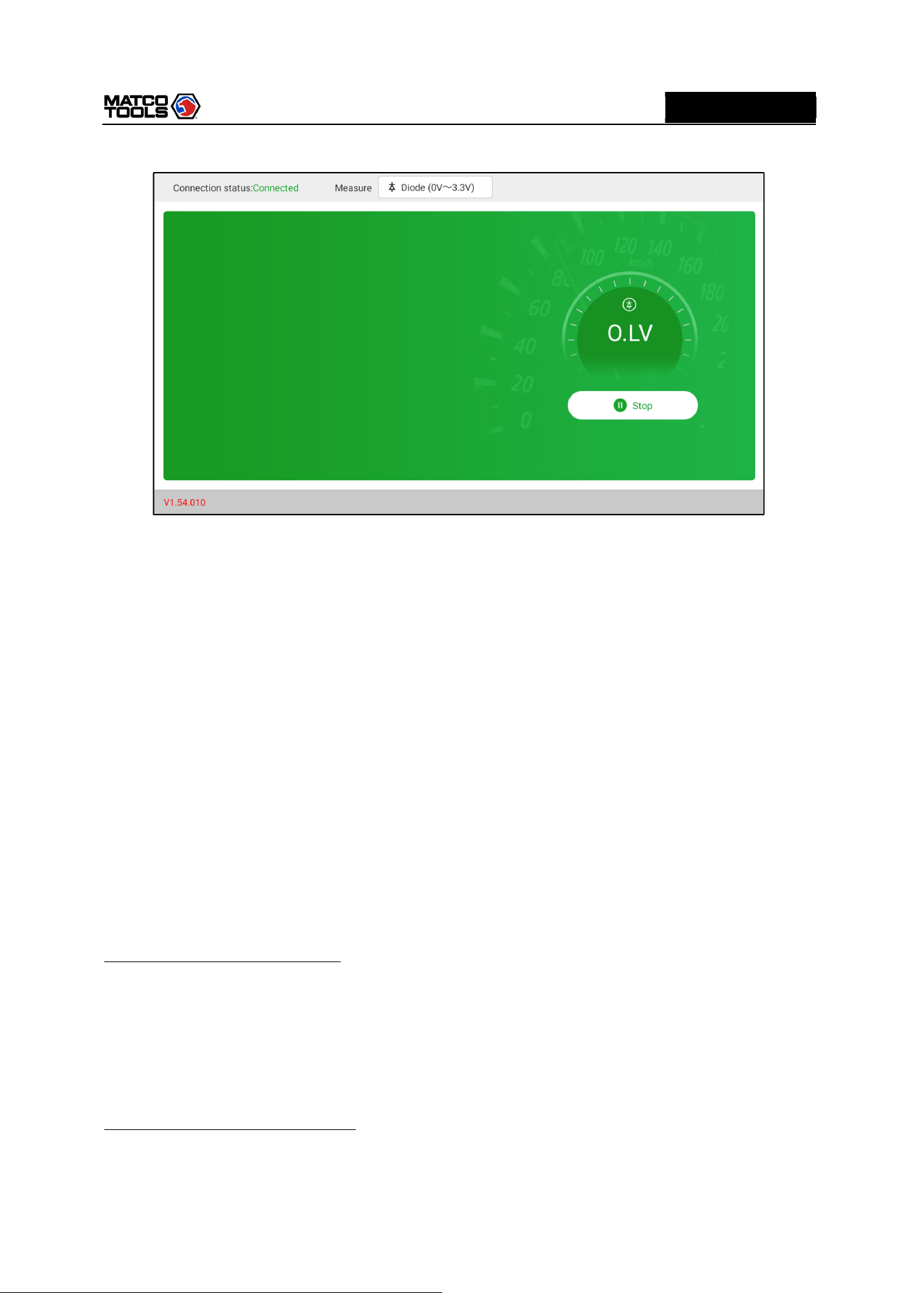
4.1.4 Diode Measurement
This MAX2CSCOPE can measure light-emitting diode and rectifier diode. The way test pen is placed
is the same with voltage measurement.
1.
Tap Toolbox -> Multimeter on the diagnostic tool to enter the following screen.
2.
Select Diode, tap Not connected to search for MAX2CSCOPE. When it is successfully connected,
the diagnostic tool will display connection status.
High Level 2-Channel Lab Scope with built in Multimeter
22
MD
MAX2CSCOPE
A
3.
Insert black test pen into COM terminal of MAX2CSCOPE, insert red test pen into V/Ω terminal of
MAX2CSCOPE.
4.
Attach red test pen to positive end of diode, black test pen to negative end of diode. Keep test pen
firmly attached to diode.
5.
Diode forward conduction current will be displayed directly on the diagnostic tool.
4.1.5 Make-and-break Measurement
1.
Tap Toolbox -> Multimeter on the diagnostic tool to enter the following screen.
2.
Select On/Off, tap Not connected to search for MAX2CSCOPE. When it is successfully connected,
the diagnostic tool will display connection status.
3.
Insert black test pen into COM terminal of MAX2CSCOPE, insert red test pen into V/Ω terminal of
MAX2CSCOPE.
4.
Attach red and black test pen to tested point.
5.
Readings will be displayed directly on the diagnostic tool.
4.2 Test Example
Knock sensor test
(1) Detect knock sensor resistance
Turn off the ignition switch, disconnect the knock sensor wire connector, and use Resistance to detect
the resistance between the knock sensor wire terminal and the housing. The resistance should be ∞
(disconnected). If the resistance is 0Ω (connected), the knock sensor must be replaced. For the
magnetostrictive knock sensor, “Resistance” can also be used to detect the coil resistance. The
resistance should be consistent with the specified value (Refer to the service manual for the specific
data). Otherwise, the knock sensor must be replaced.
(2) Check knock sensor output signal
Remove the knock sensor plug. Use AC Voltage to check the voltage between the knock sensor wire
terminal and ground when the engine is idling. There should be a pulse voltage output. If there is no

High Level 2-Channel Lab Scope with built in Multimeter
23
MD
MAX2CSCOPE
A
voltage output, replace the knock sensor.
Cooling water temperature sensor test
(1) Detect coolant temperature sensor resistance
Check on the vehicle: Turn off the ignition switch, disconnect the coolant temperature sensor wire
connector, and use Resistance to test the resistance between the two terminals of the sensor. Its
resistance value is inversely proportional to the temperature (negative temperature coefficient) and
should be less than 1kΩ during warm-up.
Single piece check: disconnect the coolant temperature sensor wire connector, remove the sensor from
the engine, place the sensor into the water in the beaker, heat the water in the beaker, and use
Resistance to test the resistance between the two terminals of the sensor under different water
temperature conditions. Compare the measured value with the standard value. If the standard value is
not met, the coolant temperature sensor should be replaced.
(2) Detect coolant temperature sensor output signal voltage
Install the coolant temperature sensor, insert the sensor wire connector, turn on the ignition switch, and
test the sensor output voltage signal between the two terminals of the coolant temperature sensor wire
connector. The measured voltage value should vary inversely with the coolant temperature. When the
coolant temperature sensor harness is disconnected and the ignition switch is on, the voltage should be
about 5V.
4.3 Attention
1.
Before usage, please reset APP value on the multimeter to zero.
2.
The tip of the test pen is metal, do not touch it with hands during measurement, otherwise it might
cause electric shock and affect measurement results.
3.
Before test, please check measurement range and socket into which the test pen is inserted,
perform test after checked with no error.
4.
If it is unable to estimate measured value, choose max measurement range, and shift to suitable
range based on measured results.
5.
It is strictly forbidden to shift measurement range when measuring high voltage or large
current, as it can cause electric arc to burn switch contact. If you want to change range, please
disconnect metal contact tip first.
6. To avoid instrument damage, it is strictly forbidden to measure resistance when tested
circuit is powered on.
7.
When you want to measure DC current with multimeter, please reset it to zero first, then select
suitable measurement range. Current varies in different modules, please refer to module mark to
shift measurement range. During measurement, connect the multimeter in series, and measure
circuit one by one. The bypass voltage can be disconnected. Please be aware that parallel connection
of multimeter is forbidden, as it can cause multimeter damage and personnel injury.

High Level 2-Channel Lab Scope with built in Multimeter
24
MD
MAX2CSCOPE
A
5 Care & Maintenance
General Care
Do not store or leave the MAX2CSCOPE where the device will be exposed to direct sunlight for long
periods of time.
Caution
To avoid damages to the device or probes, do not expose them to sprays, liquids or solvents.
Cleaning
Inspect the device and probes as often as operating conditions require. Make sure the device is
disconnected from all power sources.
To clean the exterior surface, perform the following steps:
1. Remove loose dust on the outside of the MAX2CSCOPE and probes with a lint-free cloth. Use care to
avoid scratching the clear glass display filter.
2. Use a soft cloth dampened with water to clean the device.
Caution
To avoid damages to the surface of the device or probes, do not use any abrasive or chemical cleaning
agents.

High Level 2-Channel Lab Scope with built in Multimeter
25
MD
MAX2CSCOPE
A
If you have any questions on the operation of the unit, please contact Matco customer service number:
877-853-3738.
Statement: We reserve the rights to change the product design and specifications without prior notice.
The appearance and color of the actual product may be different from those shown in the manual. Please
refer to the actual product. We have tried our best to make all the descriptions in the manual accurate,
but it is still inevitable that there are inadequacies. If you have any questions, please contact the dealer or
after-sales service center. We will not bear any consequences arising from misunderstanding.
