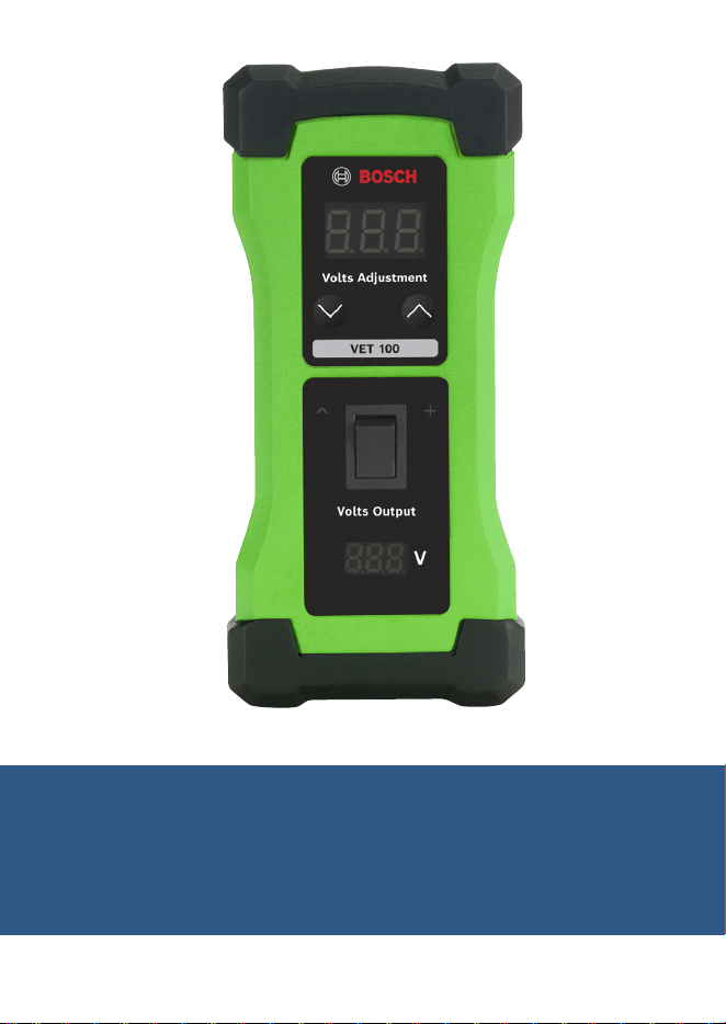
VET 100 Circuit Analysis Tool
Operating Instructions

en
|
2
|
Operating Instructions
| VET 100
Circuit Analysis Tool
1699501321 | REV. A | May 2019
Contents
1 Introduction 2
2 Safety Warnings 2
3 Tool Components 4
4 Testing Faulty Sensors 5
5 Testing Faulty Sensor Wiring or ECM 6
6 Circuit Analysis Sensor Theory 6
7 Technical Tips 7
8 Warranty Terms and Conditions 8
1 Introduction
The VET 100 Circuit Analysis Tool is used in conjunction with an
on-board diagnostic (OBD) scan tool, such as the Bosch ADS 625,
to identify faulty engine sensors, wiring harnesses, and/or issues
with the engine control module (ECM).
Operating Instructions
| VET 100
Circuit Analysis Tool | 3
|
en
1699501321 | REV. A | May 2019
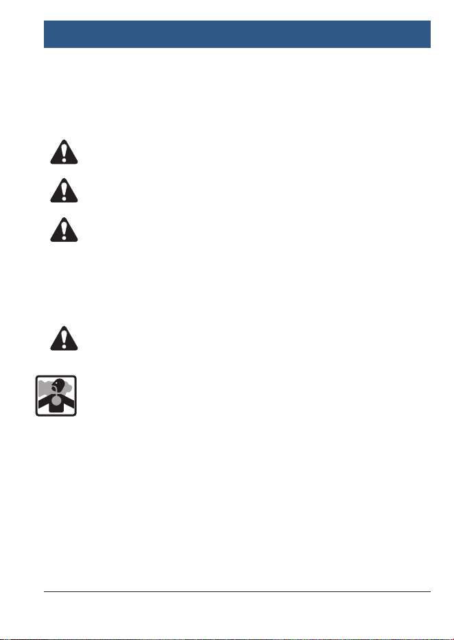
2 Safety Warnings
Explanation of Safety Signal Words
The safety signal word designates the degree or level of hazard
seriousness.
DANGER: Indicates an imminently hazardous situation
which, if not avoided, will result in death or serious injury.
WARNING: Indicates a potentially hazardous situation
which, if not avoided, could result in death or serious injury.
CAUTION: Indicates a potentially hazardous situation
which, if not avoided, may result in minor or moderate injury.
CAUTION: Used without the safety alert symbol indicates
a potentially hazardous situation which, if not avoided,
may result in equipment damage.
DANGER: To prevent serious personal injury or
death,
}When an engine is operating, keep the service area well
ventilated or attach a building exhaust removal system to
the engine exhaust system. This will prevent the buildup
and inhalation of carbon monoxide, an odorless, poisonous
gas that can lead to serious personal injury or death.
en
|
4
|
Operating Instructions
| VET 100
Circuit Analysis Tool
1699501321 | REV. A | May 2019
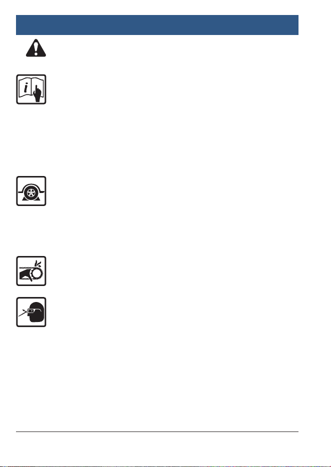
WARNING: To prevent personal injury and/or
equipment damage,
}Study, understand, and follow all safety precautions and
operating instructions before using the VET 100 Circuit
Analysis Tool. If the operator cannot read the instructions,
safety precautions and operating instructions must be
read and discussed in the operator’s native language.
}Do not make any ground or jumper connections between
the sensor wires and any other electrical circuits on the
vehicle unless directed by the vehicle’s service manual.
}Before servicing, ensure that (1) the vehicle is in
park (automatic transmission) or neutral (manual
transmission), (2) the emergency brake is engaged, and
(3) the wheels are chocked.
}After servicing the vehicle, reset the code memory using
the OBD scan tool.
}Keep all body parts clear of the drive belts, high voltage
plug wires, and hot surfaces located underneath the hood
of the vehicle.
}Wear eye protection that meets ANSI Z87.1, CE EN166,
AS/NZS 1337, and OSHA standards.
}Wear personal protective equipment that meets ANSI/ISEA
and OSHA standards.
}Use the VET 100 Circuit Analysis Tool only on vehicles with
a computerized engine control system.
}Do not use the VET 100 Circuit Analysis Tool for anything
other than its intended purpose.

Operating Instructions
| VET 100
Circuit Analysis Tool | 5
|
en
1699501321 | REV. A | May 2019
}No alteration shall be made to this tool.
}Inspect the condition of the VET 100 Circuit Analysis Tool
before each use; do not use if damaged, altered, or in poor
condition.
}Replace a damaged VET 100 Circuit Analysis Tool using
only the replacement components listed in Section 3 of
the operating instructions.
}Refer to the service manual for the vehicle being serviced.
Adhere to all diagnostic procedures and precautions.
Failure to do so could result in personal injury or
otherwise unneeded repairs.
en
|
6
|
Operating Instructions
| VET 100
Circuit Analysis Tool
1699501321 | REV. A | May 2019
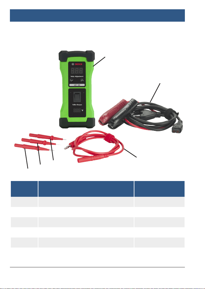
3 Tool Components
Item
No.
Description Part No. / Kit No.
1 VET 100 3920
2 1.83m/6ft Battery Cable 3920-01
3 1m/3.3ft Cable for Probe Tip 3920-02
4 2mm Flat Terminal 3920-02
5 2mm Probe Tip 3920-02
6 Pin Tip Probe 3920-02
1
2
3
4
5
6

Operating Instructions
| VET 100
Circuit Analysis Tool | 7
|
en
1699501321 | REV. A | May 2019
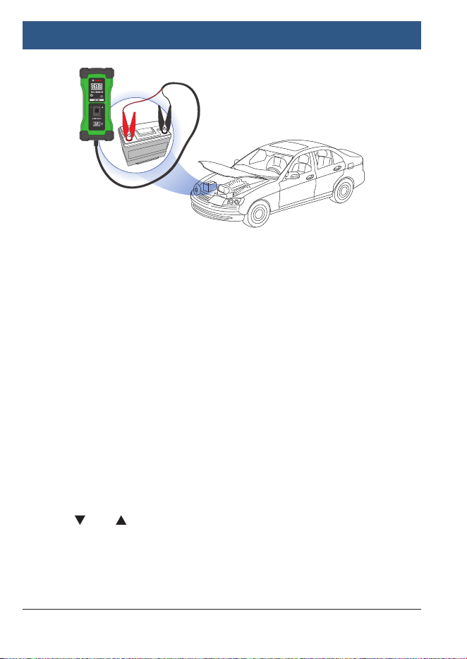
4 Testing Faulty Sensors
1. Turn off the vehicle’s ignition before disconnecting any of the
sensors from the engine.
2. Connect the VET 100 Circuit Analysis Tool to the vehicle’s
battery using the positive and negative clamps. See Figure 1.
NOTE: The voltage of the battery is displayed at the bottom
of the VET 100 Circuit Analysis Tool.
3. Refer to the vehicle’s electrical wiring diagrams to determine
which sensor signal wire to probe with voltage. See vehicle’s
service manual for the correct operating voltage of the
sensor being tested.
4. Set the voltage on the VET 100 Circuit Analysis Tool to the
correct voltage for the sensor being tested using the and
arrows. NOTE: The voltage range for the VET 100 Circuit
Analysis Tool is 0.5 V to 7 V, and can be adjusted in 0.5 V
increments.
5. Apply voltage to the correct sensor signal wire by touching
the positive (red) test probe and pushing the power switch
on the VET 100 Circuit Analysis Tool.
6. Read the OBD scan tool (not included with VET 100 Circuit
Analysis Tool) to see if the reading displays the same voltage
that was applied by the VET 100 Circuit Analysis Tool. If the
voltage reading is lower than what was applied, the wiring
harness or ECM has a potential voltage loss and may need
repair or replacement. If the voltage is the same as what was
applied, the sensor is faulty and will need to be replaced.
NOTE: The voltage signal may translate to a pressure or
temperature reading.
en
|
8
|
Operating Instructions
| VET 100
Circuit Analysis Tool
1699501321 | REV. A | May 2019
Figure 1
5 Testing Faulty Sensor Wiring or ECM
1. If continuing from Section 4, “Testing Faulty Sensors,”
reconnect all sensors to the engine before turning on the
vehicle’s ignition.
2. Connect the VET 100 Circuit Analysis Tool to the vehicle’s
battery using the positive and negative clamps. See Figure 1.
NOTE: The voltage of the battery is displayed at the bottom
of the VET 100 Circuit Analysis Tool.
3. Refer to the vehicle’s electrical wiring diagrams to determine
which sensor signal wire to probe with voltage. See vehicle’s
service manual for the correct operating voltage of the
sensor signal wire being tested.
4. Set the voltage on the VET 100 Circuit Analysis Tool to the
correct voltage for the sensor signal wire being tested using
the and arrows. NOTE: The voltage range for the VET
100 Circuit Analysis Tool is 0.5 V to 7 V, and can be adjusted
in 0.5 V increments.

Operating Instructions
| VET 100
Circuit Analysis Tool | 9
|
en
1699501321 | REV. A | May 2019
5. Apply voltage to the ECM pin of the correct sensor signal
wire by touching the positive (red) test probe directly to the
pin and pushing the power switch on the VET 100 Circuit
Analysis Tool.
6. Read the OBD scan tool (not included with VET 100 Circuit
Analysis Tool) to see if the reading displays the same voltage
that was applied by the VET 100 Circuit Analysis Tool. If the
voltage reading matches to what was applied, the wiring
harness is faulty; however, if the voltage reading is lower
than what was applied, the ECM is not processing the
voltage signal properly and may need to be replaced. NOTE:
The voltage signal may translate to a pressure or temperature
reading.
6 Circuit Analysis Sensor Theory
Computer Controlled Sensors:
Sensors are designed to monitor various conditions that
could affect a vehicle’s performance. These signals are used
by the ECM to control the fuel mixture, ignition timing, idle
speed, exhaust gas recirculation (EGR) valve, purge valve, and
other emission functions. A problem with any of the ECM’s
sensors can result in a range of drivability issues including,
but not limited to: hard starting, poor idle, intermittent fault,
stalling, excessive idle speed, excessive tailpipe emissions, or
improper shifting. The VET 100 Circuit Analysis Tool can input
voltage to both the sensors and the ECM, allowing the user to
determine whether the sensors are working properly and/or if
the ECM is properly receiving the sensor signal.
Computer controlled sensors fall into one of two categories.
See next page.
en
|
10
|
Operating Instructions
| VET 100
Circuit Analysis Tool
1699501321 | REV. A | May 2019
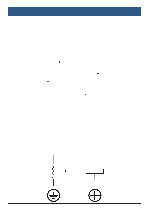
1. Variable Resistance Sensors
These types of sensors are also referred to as “2-Wire”
sensors. They usually contain two wires—a voltage
supply wire and a signal return wire—that connect to
the ECM. These sensors include: coolant temperature
sensors, manifold air temperature sensors, and outside
air temperature sensors. See Figure 2.
2. Variable Voltage Sensors
These types of sensors are also referred to as “3-Wire”
sensors. They usually contain three wires—a voltage
supply wire, a signal return wire, and a ground wire—that
connect to the ECM. These sensors include: throttle
position sensors, manifold absolute pressure (MAP)
sensor, barometric pressure sensor, and some mass
airflow sensors. See Figure 3.
Figure 3
Figure 2
Computer
Engine
Sensor
Signal
Out
Data
In
Controller
Computer
Reference Supply Voltage
Sensor
Signal output
(variable voltage)

Operating Instructions
| VET 100
Circuit Analysis Tool | 11
|
en
1699501321 | REV. A | May 2019
7 Technical Tips
}
The Circuit Analysis Tool’s maximum voltage of 7 V is designed
to safely accommodate the operating range of most ECMs.
}
Use Ohm’s Law (R = V/I), where the resistance (R) in ohms
is equal to the voltage (V) in volts divided by the current (I)
in amps, to calculate the voltage resistance. If the back-end
voltage received by the ECM is lower than the front-end voltage
emitted from the Circuit Analysis Tool, there is a voltage drop.
This voltage drop indicates corrosion of either the sensor or
wiring harness, causing less voltage to reach the ECM than
normal.
}
Consult a wiring diagram to confirm correct voltage at sensors.
}
Connect the Circuit Analysis Tool to 12 or 24 V battery systems
only. A flashing red light will appear on the user interface if
battery voltage is low.
}
Use this tool along with an OBD scan tool to identify the cause
of a fault code and to fix issues that generate fault codes on
vehicle components including, but not limited to: accelerator
pedal voltage up to 5 V, EGR signal voltage up to 5 V, diesel
regulator valve, throttle bodies, camshaft sensors, crankshaft
sensors, mass air flow (MAF) sensors, MAP sensors, parking
sensors, temperature sensors, oil pressure sensors, and trans-
ducer-based components.

en
|
12
|
Operating Instructions
| VET 100
Circuit Analysis Tool
1699501321 | REV. A | May 2019
8 Warranty Terms and Conditions
This warranty is expressly limited to the original retail
buyers of Bosch new or refurbished electronic diagnostic
tools (“units”).
• New Bosch Units are warranted against defects in materials and
workmanship for one year (12 months) from date of delivery.
• Cables and Accessories are warranted against defects in materials
and workmanship for 90 days (3 months) from date of delivery.
This warranty does not cover any Unit that has been abused, altered,
used for a purpose other than that for which it was intended, or used
in a manner inconsistent with the operating instructions. The sole
and exclusive remedy for any Unit found to be defective is repair or
replacement, at the option of Bosch. In no event shall Bosch be liable
for any direct, indirect, special, incidental, or consequential damages
(including lost profit) whether based on warranty, contract, tort,
or any other theory. The existence of a defect shall be determined
by Bosch in accordance with procedures established by Bosch.
No person is authorized to make any statement or representation
altering the terms of this warranty.
Disclaimer
The above warranty is in lieu of any other warranty, expressed or
implied, including any warranty of merchantability or fitness for a
particular purpose.
Technical Service
If you have any questions on the operation of the product, please
call 855-267-2483, or visit www.boschdiagnostics.com.
Bosch Automotive Service Solutions Inc.
655 Eisenhower Drive • Owatonna, MN 55060 USA
