14 22 63
64 83
88
2X
4X
3X
2X
2X
6X
6X
3X
*
*
14 22 38
39 83
89
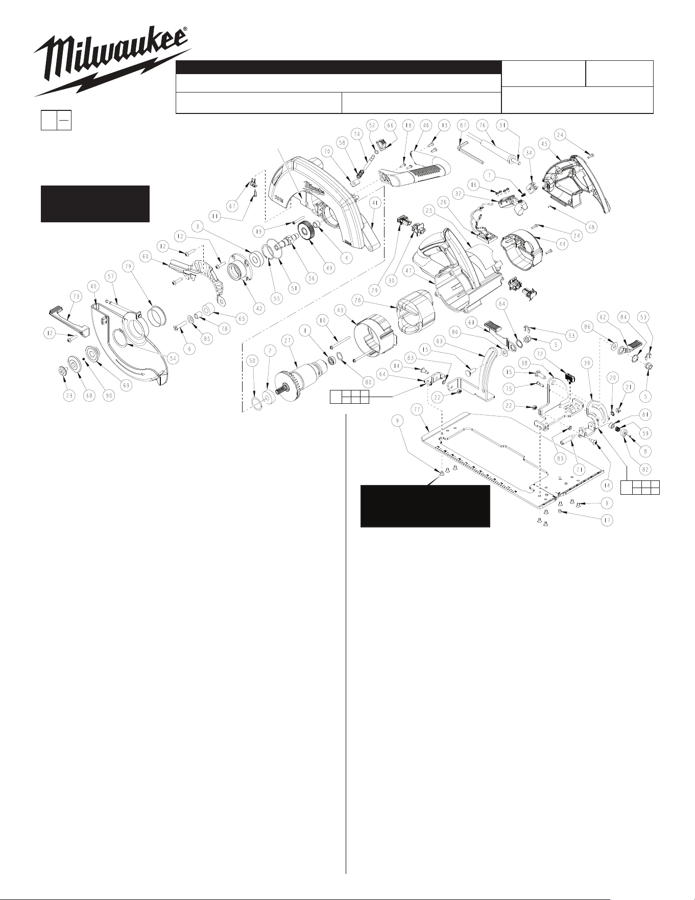
FIG. PART NO. DESCRIPTION OF PART QTY. REQ.
)1( gnirpS tneteD leveB 0408-05-04 85
)1( gnirpS noisserpmoC 0738-05-04 95
60 42-14-1215 Upper Guard Baffl )1( e
61 42-36-1121 Depth Lever Assembly (1)
62 42-36-1122 Bevel Lever Assembly (1)
)1( tekcarB htpeD --------------- 36
64 --------------- Elevation Pivot Bracket (1)
)1( repmuB rebbuR 5220-83-24 56
)1( nottuB kcoL eldnipS 5010-24-24 66
)1( pilC gniniateR 0680-86-24 76
)1( egnalF edalB retuO 3620-43-34 86
)1( egnalF edalB rennI 4620-43-34 96
)1( teksaG rebiF 0121-44-34 07
)1( niP egniH 5200-07-3
4 17
)1( kcoL ediuG egdE 0550-89-34 27
)1( reveL drauG rewoL 5760-01-44 37
)1( kcoL eldnipS 0221-02-44 47
)1( niP tneteD leveB 5511-06-44 57
)1( feileR niartS 0500-67-44 67
)1( eohS 3830-61-54 77
)1( eveelS repmuB 0930-22-54 87
79 45-22-0765 Lower Guard Sleeve (1)
80 45-88-0577 Wave Spring Washer (1)
)1( rehsaW citsalP 0931-88-54 18
)1( paC leveB 5141-88-54 28
)2( rehsaW devruC 5341-88-54 38
)2( rehsaW evaW 3017-88-54 48
)1( rehsaW 0847-88-54 58
)2( r
ehsaW 0648-88-54 68
)1( yeK xeH 5430-69-94 78
88 14-74-0340 Shoe Bracket Assembly (1)
89 14-74-0330 Shoe Bevel Assembly (1)
90 48-40-4170 10-1/4" Saw Blade (Not Shown) (1)
28-35-0080 Rip Fence (Not Shown) (1)
42-55-6470 Steel Carrying Case (Not Shown) (1)
10-1/4" CIRCULAR SAW
58-01-0756
54-40-1940
Sept. 2018
B49A
6470-21
WIRING INSTRUCTION
REVISED BULLETIN
DATE
SERVICE PARTS LIST
MILWAUKEE ELECTRIC TOOL CORPORATION
13135 W. LISBON RD., BROOKFIELD, WI 53005
Drwg. 5
BULLETIN NO.
STARTING
SERIAL NO.
SPECIFY CATALOG NO. AND SERIAL NO. WHEN ORDERING PARTS
CATALOG NO.
00
0
EXAMPLE:
Component Parts
(Small #) Are
Included When
Ordering The
Assembly (Large #).
FIG. PART NO. DESCRIPTION OF PART QTY. REQ.
)1( gniraeB llaB 7480-40-20 1
)1( gniraeB llaB 1921-40-20 2
)1( gniraeB llaB 7471-40-20 3
)1( gniraeB eldeeN 0110-05-20 4
)2( tuN xeH leveB mm8 0302-55-50 5
6 05-70-0335 M8 x 40mm Flat Hd. T-30 Screw (1)
7 05-71-0017 M4 x 10mm T-15 Screw (1)
8 05-74-0950 M3 x 5mm Flat Hd. T-20 Screw (1)
9 05-74-1005 M6 x 10mm Flat Hd. T-25 Screw (9)
10 05-74-0980 M5 x 65mm T-25 Field Screw (2)
11 05-74-0985 M4 x 12mm Pan Hd. Tapt. T-20 Screw (1)
12 05-74-0990 M5 x 15mm Pan Hd. T-25 Screw (7)
13 05-74-0995 8-16 x .5 Pan Hd. T-20 Screw (2)
14 05-74-1000 M5 x 10mm T-25 Screw (2)
15 05-77-1360 M8 x 23mm Carriage Bolt (2)
16 05-78-0305 M3.5 x 7mm T-15 Switch Screw (4)
17 05-84-0980 M5 x 10mm Set Screw (1)
18 05-86-0200 M5 x 11mm T-20 Screw (2)
19 05-88-5988 M5 x 35mm Pan Hd. Slt. T-20 Screw (3)
20 05-90-0160 External Tooth Lock Washer (1)
)1( tuN xeH 6M 0500-75-60 12
)2( tuN xeH mm8 x 5M 0260-55-50 22
23 06-75-0038 5/16"-18 x 9/16" Blade Screw (1)
24 06-82-7270 8-16 x 5/8" Pan Hd. Slt. Plast. T-20 Screw (8)
25 12-20-6470 Service Nameplate Kit (1)
)1( ylbmessA BCP 0880-02-41 62
)1( erutamrA ecivreS 0550-07-61 72
)1( dleiF ecivreS 0550-07-81 82
)2( ylbmessA hsurB 5300-81-22 92
30 22-22-0030 Brush Tube Assembly (2)
)1( teS droC 5156-46-22 13
)1( hctiwS 3181-66-32 23
)1( kcolB lanimreT 0410-47-32 43
)1( tekcarB leveB --------------- 83
)1( etalP leveB --------------- 93
)1( drauG rewoL 2660-14-82 04
41 28-41-0673 Upper Guard/Gearcase (1)
)1( buH eldnipS 5610-35-82 24
43 31-05-0017 Fan Baf
fl )1( e
44 31-15-0463 Motor Housing Cover (1)
)1( tfeL - evlaH eldnaH 5840-44-13 54
46 31-44-0488 Bale Handle Assembly (1)
)1( gnisuoH rotoM 6510-05-13 74
)1( gulP rebbuR 5010-35-13 84
)1( raeG tuptuO 5223-57-23 94
)1( gniR-O 0610-04-43 05
)1( gniR-O 5610-04-43 15
)1( pilC-E 0570-06-43 25
)2( pilC-E 0332-06-43 35
54 34-80-0900 External Retaining Ring (1)
55 34-80-2975 40mm Retaining Ring (1)
)1( eldnipS tuptuO 0746-05-83 65
)1( gnirpS drauG rewoL 3577-05-04 75
SEE REVERSE SIDE
FOR LUBRICATION
AND SERVICE NOTES
Carriage Bolt (15) is to be routed
through the square hole in
Upper Guard/Gearcase (41)
prior to assembly
onto the Depth
Bracket (63).
*
NOTE: For item #9, some earlier
tools may have used 05-74-0970
(M5 x 10 Flat Hd. T-20 screw). A
drop of "Blue" Loctite, Type 242 is
needed on the threads.

FIG. LUBRICATION
2,41,50 Apply a light fi lm of grease or oil to the O-Ring (50) and the bearing bore in the Upper Guard/
Gearcase (41) before assembling the Armature Bearing (2).
41 Place 1/2 Oz. Type "Y" Grease, No. 49-08-5270 in gear cavity of Upper Guard/Gearcase (41).
NOTE: 90-95% of the old grease must be removed prior to new grease being added.
FIG. NOTES
1 Orient the Ball Bearing (1) such that the seal faces the commutator of the Armature (27).
4 Orient the Needle Bearing (4) such that the vendor I.D. is facing the Gear (49). Press the bear
ing .045" subfl ush to the gear cavity wall in the Upper Guard/Gearcase (41).
6 Apply "Blue" Loctite, Type 242 to threads of the Rubber Bumper Screw (6) prior to assembly.
8 Apply "Blue" Loctite, Type 242 to the threads of the Bevel Detent Screw (8) prior to assembly.
40 Functionally check the Lower Guard (40) with the saw set at full depth of cut. Place the saw up
side down with the Shoe (77) horizontal. Fully retract the Guard using Guard Lever (73) and
then release it. The Guard must close briskly. Repeat Guard check two more times.
54 Orient External Retaining Ring (54) such that the beveled face is towards Lower Guard (40).
56,74 Functionally check the Spindle Lock (74). Spindle Lock must return briskly when released from
engagement in Output Spindle (56).