
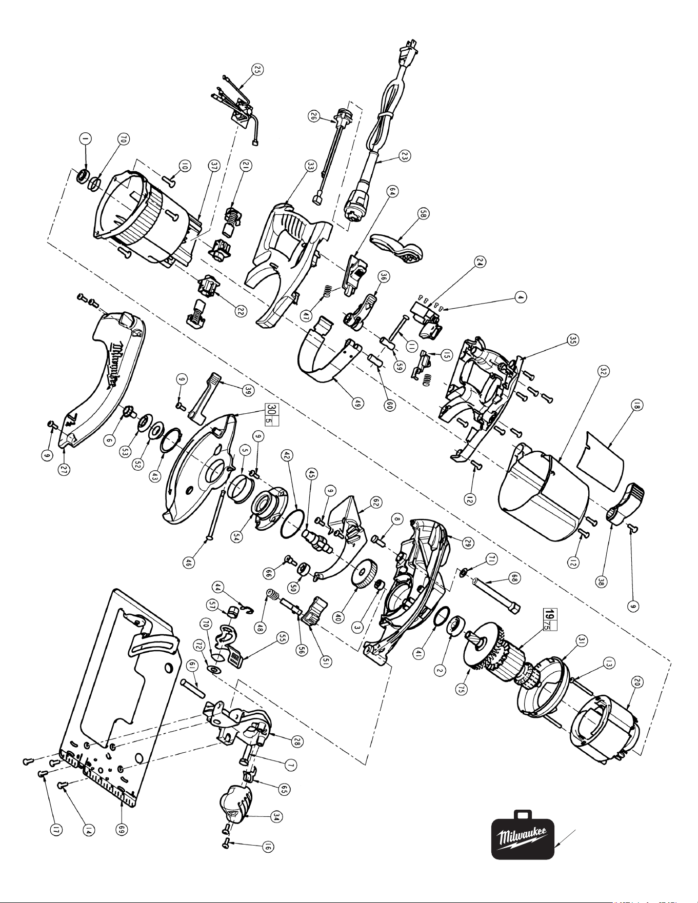
29,31 Orientthebafe
with the crush
ribs aligned
with the screw
holes in the motor
housing and the
locator tabs aligned
and seated
as shown.
30 Functionally check the lower guard with the saw set at full
depth of cut and zero degree bevel. Place the saw upside
down with the shoe horizontal. Retract the lower guard
100%. Release the lower guard lever. The guard should
return in a brisk manner.
38 When tight, the depth adjustment lever should be parallel
( ±20°) with the shoe.
43 Orient the external retaining ring such that the beveled face
is towards the guard.
55 When tight, the bevel adjustment lever should be bottomed
out on the shoe. (Up to .100" off the shoe is acceptable).
28,65 Position the pointer such that the arrow indicates between
the zero and one degree mark on the bevel plate scale.
Loosen front handle screws to adjust pointer.
71 Orient the washer such that the rounded edge is towards
the depth rail.
72 Orient the washer such that the rounded edge is towards
the bevel plate.
FIG. PART NO. DESCRIPTION OF PART NO. REQ.
1 02-04-0847 Ball Bearing (1)
2 02-04-1850 Ball Bearing (1)
3 02-50-2423 Needle Bearing (1)
4 05-78-0120 Switch Screw (4)
5 45-22-0605 Lower Guard Sleeve (1)
6 06-75-0035 5/16-18 x 9/16" Blade Screw (1)
7 06-75-5850 5/16 -18 L.H. Thread Bolt (1)
8 06-75-5860 1/4-20 x 3/4" Hex Hd. Screw (1)
9 06-82-5314 10-24 x 1/2" Pan Hd. Taptite T-25 (11)
10 06-82-5358 12-24 x 3/4" Pan Hd. Taptite T-27 (3)
11 06-82-5474 10-24 x 1-3/4" Pan Hd. Taptite T-25 (1)
12 06-82-7270 8-16 x 5/8" Pan Hd. Slt. Plastite T-20 (10)
13 06-82-7395 8-16 x 1-3/4" Pan Hd. Plastite T-20 (2)
14 05-88-0305 K50 x 16mm Delta PT (3)
15 44-20-0640 Slide Lock (1)
16 06-82-0090 10-14 x .562 Plastite T-25 (2)
17 06-95-6290 M5 x 2.24 x 18 PH (PT) (1)
18 12-20-6394 Service Nameplate Kit (1)
19 16-70-0255 Armature (1)
20 18-70-1500 Field (1)
21 22-18-0065 Brush Assembly (2)
22 22-22-0030 Brush Tube Assembly (2)
23 48-76-5110 Quik-Lok Cord Set (1)
24 23-66-2176 Switch (1)
25 14-20-0526 Electronic Brake Assembly (1)
26 22-56-0858 Blade Housing Assembly (1)
27 25-20-0120 Upper Guard Cover (1)
28 14-67-0256 Bevel Bracket Assembly (1)
29 28-14-0100 Gearcase (1)
30 28-41-1032 Lower Guard Kit (1)
31 31-05-0045 Bafe (1)
32 31-15-0461 Motor Cover (1)
33 31-44-0081 Right Handle Half (1)
34 31-44-0060 Front Handle (1)
35 31-44-0091 Left Handle Half (1)
36 31-44-2156 Handle Lever (1)
37 31-50-0060 Motor Housing Assembly (1)
38 31-52-0015 Depth Lever (1)
39 31-52-0025 Guard Lever (1)
40 32-75-3205 Gear (1)
41 34-40-1375 O-Ring (1)
42 34-40-1380 O-Ring (1)
43 34-60-0320 External Retaining Ring (1)
44 34-60-2330 Klip Ring (1)
45 38-50-0060 Spindle (1)
46 40-50-0045 Guard Spring (1)
47 40-50-0055 Compression Spring (2)
48 40-50-8041 Spring (1)
49 42-16-0160 Handle Band (1)
50 42-38-0222 Rubber Bumper (1)
51 42-42-0275 Spindle Lock Button (1)
52 43-34-0790 Inner Flange (1)
53 43-34-0795 Outer Flange (1)
54 43-78-0155 Hub Assembly (With Bearing) (1)
55 44-10-0130 Bevel Adjustment Lever (1)
56 44-20-0510 Spindle Lock Pin (1)
57 44-40-0780 Adjustment Nut (1)
58 44-52-0681 Grip (1)
59 44-60-0075 Thru Pin (1)
60 44-60-0085 Tapped Pin (1)
61 44-60-1180 Pivot Pin (1)
62 44-66-0065 Retaining Plate (1)
64 44-66-0200 Lock Plate (1)
65 44-72-0050 Pointer (1)
66 45-04-0485 Bumper Screw (1)
54-40-6027
Dec. 2009
54-40-6026
58-01-1326
984C
6394-21
7-1/4" CIRCULAR SAW with TILT-LOK
®
HANDLE and ELECT. BRAKE
REVISED BULLETIN
SERVICE PARTS LIST
BULLETIN NO.
WIRING INSTRUCTION
DATE
SPECIFY CATALOG NO. AND SERIAL NO. WHEN ORDERING PARTS
CATALOG NO.
SERIAL
NUMBER
MILWAUKEE ELECTRIC TOOL CORPORATION
13135 W. LISBON RD., BROOKFIELD, WI 53005
Drwg. 1
FIG. PART NO. DESCRIPTION OF PART NO. REQ.
68 45-08-0416 Depth Shaft (1)
69 45-16-0160 Shoe Assembly (1)
70 45-88-0577 Wave Spring Washer (3)
71 45-88-8461 Washer (1)
72 45-88-8460 5/16" Washer (1)
74 49-96-0345 Blade Wrench (Not Shown) (1)
75 22-84-0085 Fan (1)
80 48-55-9166 Carrying Case (1)
EXAMPLE:
Component Parts (Small #) Are Included
When Ordering The Assembly (Large #).
00
0
FIG. NOTE
1 Orient the ball bearing so that the seal faces the commutator.
3,29 Orient the needle bearing such that the text is facing the
gear.Pressthebearing.015"subushtothegearcavity
wall.
11 Tighten the handle lever screw such that it requires 3-7 lbs.
force to close the handle lever to the locked position.
29 Apply .320 - .360 oz. "Y" Grease, No. 49-08-5270,
to gear bore of upper guard gearcase. The grease should
be directed toward the pinion end of the armature.
See Detail A
Detail
A
= Part number change from
previous service parts list.
80