Loading ...
Loading ...
Loading ...
Getting Started
Managing Your Network Using Fluke DAQ
55
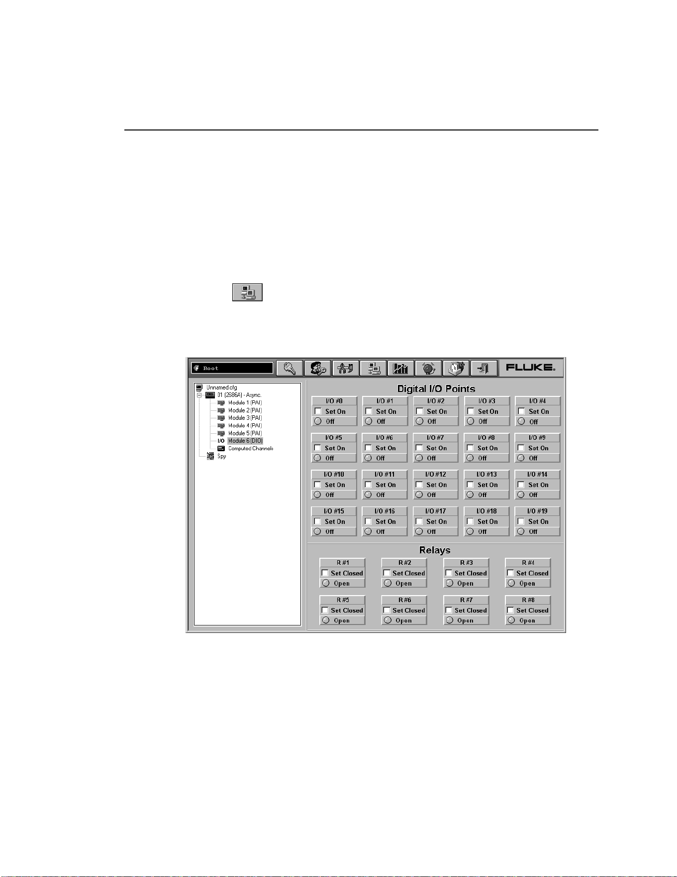
Using the Digital I/O Points Communication Dialog
You can use the Digital I/O Points Communication dialog to set any of the 8 relays
or 20 DIO pins active when an alarm condition occurs in the channel. You can also
view status of all of the relays and DIO pins and set or clear IO bits and relays.
Bits or relays you set display a green dot. Bits or relays set by an alarm have a red
dot. A bit set by an external signal has a blue dot. There is no way to set a relay
externally. When a relay is set, it has closed contacts. When a bit is set, it has a
logic low signal (also called active low).
To view digital I/O points dialog
1. Click the
on the Fluke DAQ toolbar.
2. Highlight an I/O module in the TreeView panel and the Digital I/O Points
dialog appears.
alg125s.bmp
1.888.610.7664 sales@GlobalTestSupply.com
Fluke-Direct.com
Loading ...
Loading ...
Loading ...