Loading ...
Loading ...
Loading ...
15
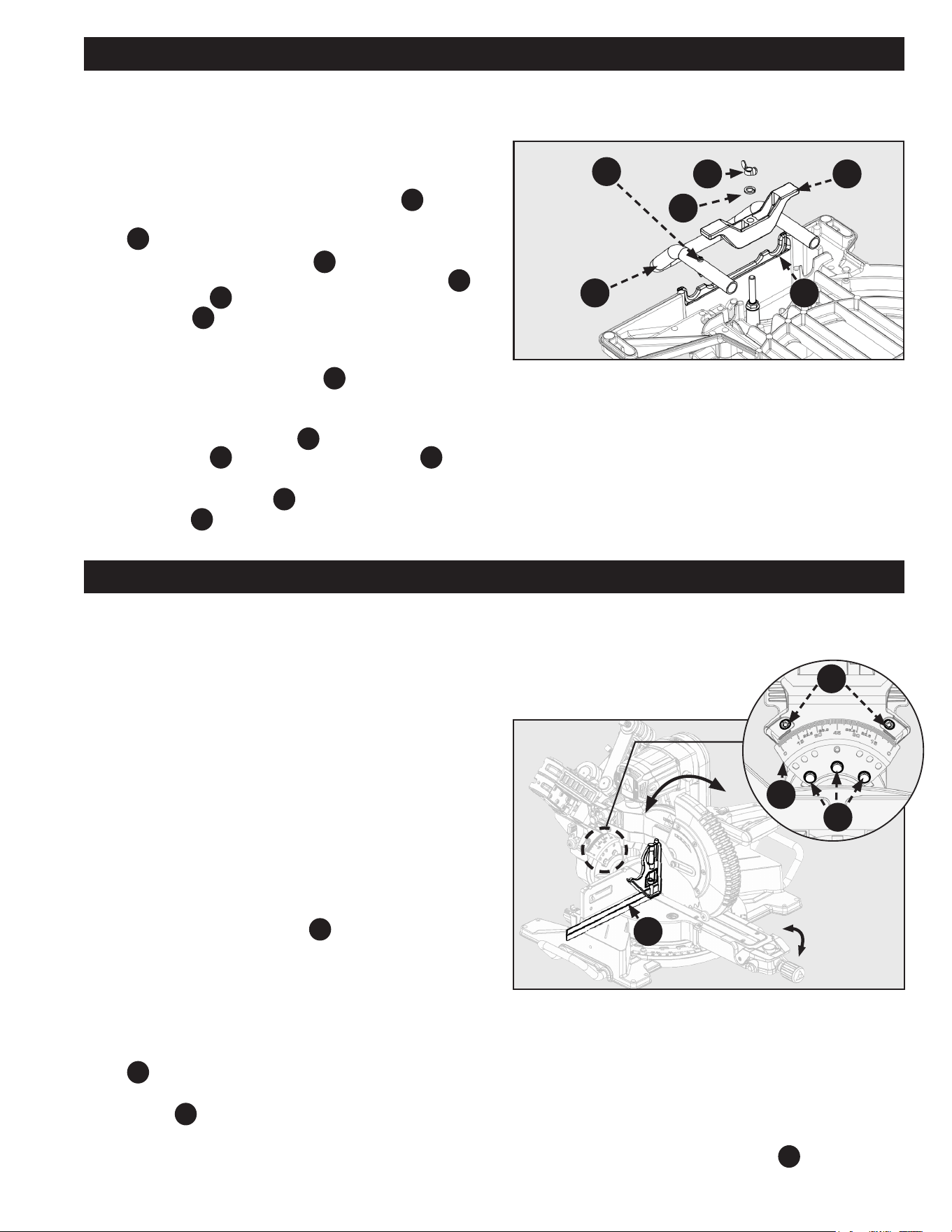
Figure 12
ASSEMBLY
ADJUSTMENTS
BEVEL ALIGNMENT
Your saw is calibrated at the factory to cut true. Over time the
saw’s calibration may drift and will need to be re-calibrated.
See Figure 12.
1. Unplug the saw.
2. Lower the saw head all the way down to the transport
position and engage the saw head lock pin to hold it
in place. Push the saw head into the fully retracted
position and engage the slide prevention lock to hold it
in place.
3. Set the miter position to 0° and engage the miter lock
knob so the table will not move.
4. Set the bevel position to 0°. Engage the bevel latch
lever, so the detent pin locks into the bevel scale.
5. Place a combination square
A
against the table and
the face of the saw blade.
NOTE: Make sure the square contacts the flat part of the
blade and not the teeth.
6. Rotate the blade by hand and check the blade-to-table
alignment at several points. If the blade face is not ush
with the square you will need to adjust the bevel scale
F6
.
7. Using a 10mm combination wrench loosen the three
screws
C
and adjust the bevel scale position. Set so
the table and blade are ush against the combination
square. Make sure the bevel lock/unlock handle is not
locked, so the scale may be adjusted.
LOCK
UNLOCK
A
F6
D
C
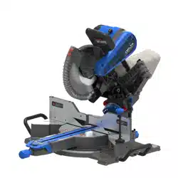
Figure 11
INSTALLING WORKPIECE
SUPPORT EXTENSIONS
See Figure 11.
To assemble the support extensions:
1. Insert one of the Support Extensions
PC5
to the
underside of the Base at the cast-in Handle cut-outs
B
.
2. Make sure Support Extension
PC5
is ush with the Base
and inserted into the rounded slots of the cut-outs
B
.
The Rivets
C
are used to prevent the Support
Extension
PC5
from sliding out of the Base during use.
These Rivets should be positioned on the inside of the
Base.
3. Place the Extension Clamp
PC6
onto the Support
Extension and the screw that is pre-attached to the
Base.
4. Once the Extension Clamp
PC6
is in place, put the Split
Lock Washer
PC7
rst and screw the Wing Nut
PC8
onto
the screw.
5. Tighten the Wing Nut
PC8
to fully secure the Support
Extension PC5 .
6. Repeat on the other side.
PC6
PC7
PC5
C
PC8
B
8. Re-tighten the three screws and re-check the blade-to-
table alignment.
NOTE: After squaring adjustments have been made, it may be
necessary to loosen the indicator screws
D
and reset them
to zero.
Loading ...
Loading ...
Loading ...