Loading ...
Loading ...
Loading ...
SDS6000A Series Digital Oscilloscope User Manual
int.siglent.com 289
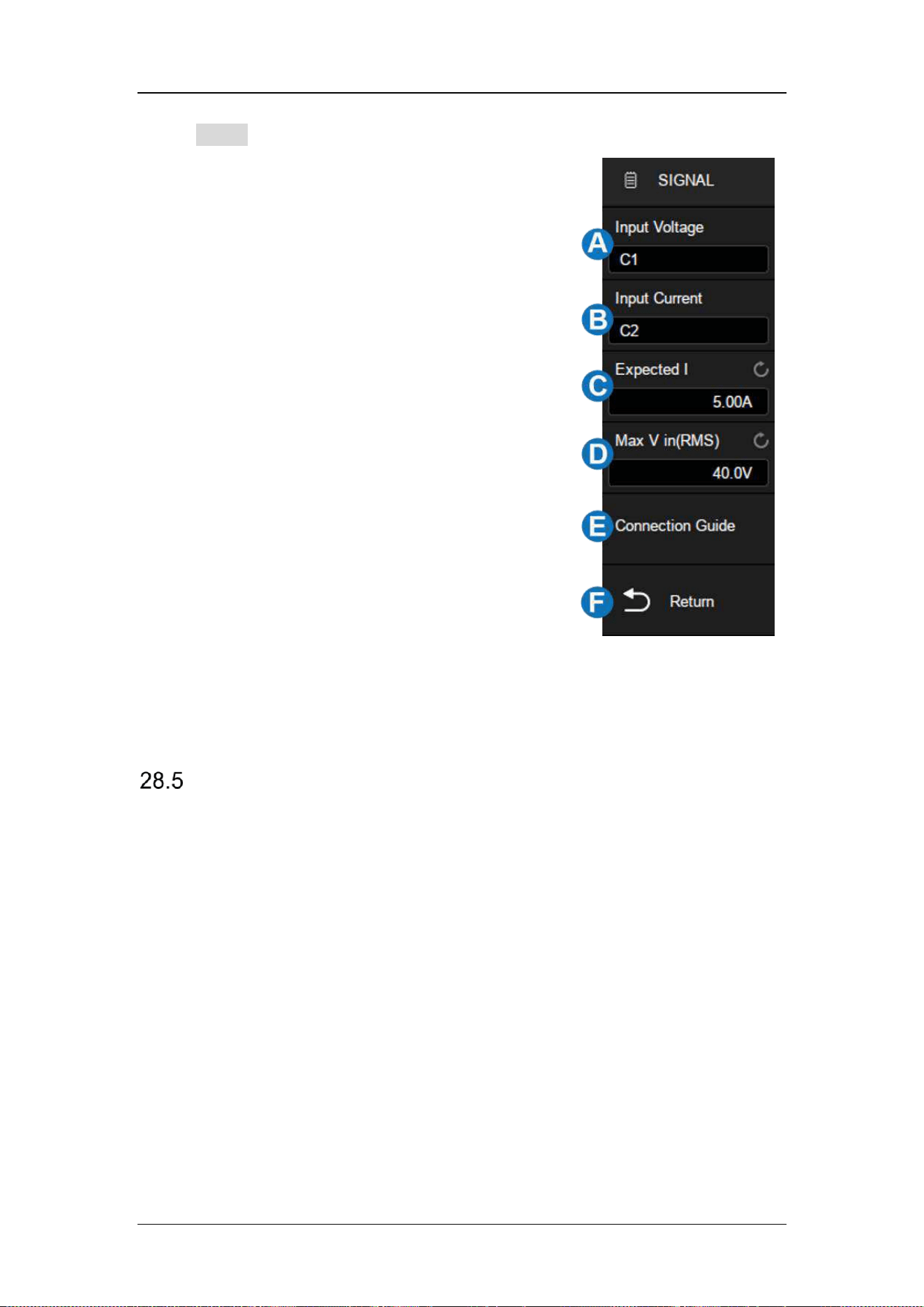
Touch Signal to recall signal settings dialog box:
A. Set the input voltage source
B. Set the input current source
C. Set the expected current value, the range is
100 mA ~ 500 A. The oscilloscope will set the
trigger level to expected current/20 and the
vertical scale of the current channel to
expected current/3.
D. Set the maximum effective input voltage
(Vrms), the range is 1 V ~ 1 kV. The
oscilloscope will set the vertical scale of the
voltage channel to maximum input voltage/6
E. View the connection guide
F. Return to the previous menu
Switching Loss
Switch loss analysis can be used to calculate the power dissipated in the
switching period.
Deskew Calibration
A relatively small skew can cause a large measurement error of switching loss,
especially during the on phase when the voltage is close to zero and the non-
on phase when the current is close to zero. This is a typical oscilloscope
dynamic range limitation when trying to measure weak voltage and (or) current
in the presence of relatively large switching voltage and (or) current.
Loading ...
Loading ...
Loading ...