MX-PROX-BOX
32.765-001_EN_03/2017
Quick Install
MX-Proximity-Box
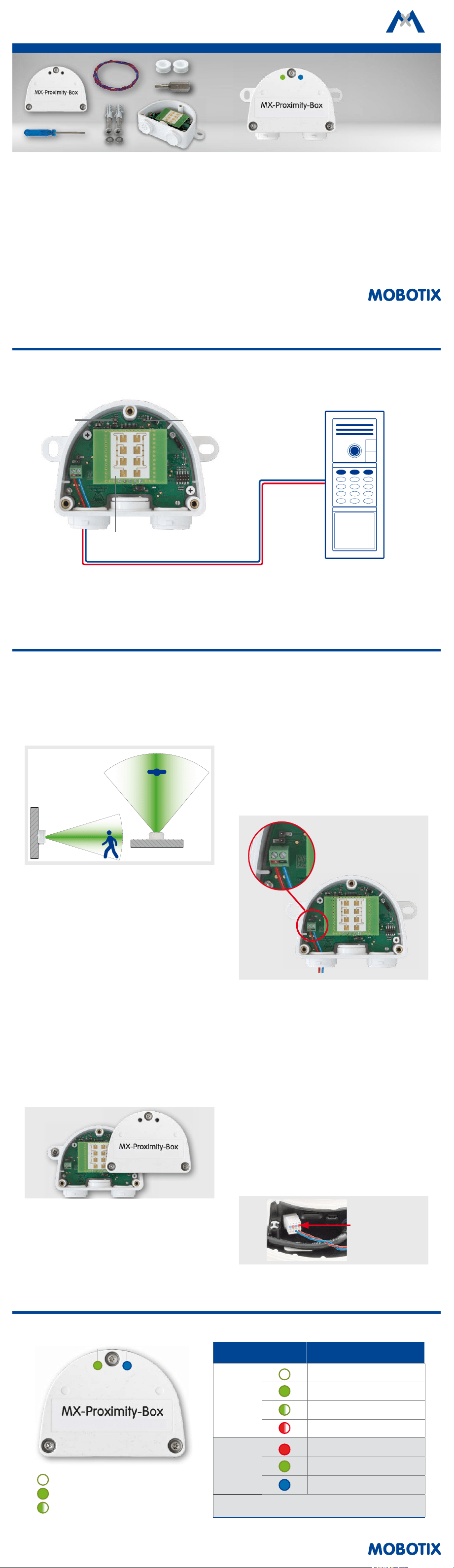
Standard Delivery
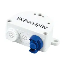
MX-Proximity-Box
Motion Detection with Radar
Sensor Technology
Radar-based detection for any
camera with MxBus connector
More information:
www.mobotix.com > Products > Accessories > Interface Boxes
• MX-Proximity-Box
• 1 screwdriver
• 1 plug 3 to 5 mm
• 1 plug 5 to 7 mm
• 1 MxBus cable 0.5 m/1.64
• 2 washers 4.3 mm dia.
• 2 stainless steel wood screws 4x40 mm
• 2 screw anchors S6
• 1 security bit TX10
Installation Instructions
1. Find a good location for installing
Select the location for installing the device so that the
objects you want to detect are within the detection area
of the box (80° horizontally, 34° vertically). Note that
the detection precision is best if the objects are moving
perpendicular to the front label of the MX-Proximity-Box:
80° horizontally
34° vertically
2. Suitable materials for concealed installation
This section is only relevant if you want to install the
MX-Proximity-Box behind any materials.
It is not possible to install the MX-Proximity-Box behind
some materials since they absorb or reect the radar
waves (e.g., metal or metal-coated surfaces). Other
materials are better suited since they absorb radar
waves only slightly (e.g., uncoated glass, plastics,
various wood-based materials, drywall).
It is highly recommended to test the detection
area before installing by covering the front of the
MX-Proximity-Box with the material you want to use!
3. Attach the box
Attach the MX-Proximity-Box at the mounting posi-
tion with the cable ports pointing downwards. Next,
remove the three security screws of the box cover using
the enclosed security bit TX10 and remove the cover.
4. Prepare the connection cables
Before proceeding, make sure there is no current on
the MxBus wires!
Cut the MxBus wires to size (2-wire, 0.6–0.8 mm diame-
ter). When using wires without sheath, strip the insulation
of the wires for 5 mm and push the wires through the
eight-wire plug (le).
When using a cable with jacket (e.g., J-Y(St)Y), remove
the pre-installed eight-wire plug and insert the appro-
priate cable plug (3 to 5 mm or 5 to 7 mm). Press the
rubber plug into the casing in such a way that the
rims stick out equally on both sides. Push the cable
through the plug, remove the sheath on a length of
15 mm/0.6 in and strip the insulation of the wires for
about 5 mm/0.2 in.
5. Connect the MxBus wires to the terminal
Connect the MxBus wires to the terminals of the
MX-Proximity-Box using the screwdriver. Make sure
to maintain the polarity (see sticker on the front of
the terminal).
6. Mount the cover
Mount the cover back onto the MX-Proximity-Box and
aix it using the cover screws.
7. Connect the MxBus wires to the opposite side
Connect the MxBus wires as described in the corre-
sponding manual to the MOBOTIX camera or to another
MxBus module connected to a camera (e.g. KeypadRFID,
MX-DoorMaster). Make sure not to exceed the overall
length of the MxBus wiring (max. 100 m/328 ).
MxBus plug
in MOBOTIX
camera
Connection Example
MOBOTIX Camera
2-wire MxBus wiring to camera
(max. 100 m/328 )
MOBOTIX IP Video Door Station
MX-T25M-Sec-D11
MOBOTIX MX-Proximity-Box
MX-PROX-BOX
LEDLED
Radar sensor
LED Signaling
LED Meaning
Operating
status
(le)
Not connected
Regular operation
Unencrypted communication
Error during communication
Radar signal
(right)
Leaving
Approaching
Movement
The intensity of the LEDs varies depending on the strength of
the reected radar waves.
Operating Status Radar Signal
LED o
LED permanently on
LED blinking
MOBOTIX AG
Kaiserstrasse
D-67722 Langmeil
Phone: +49 6302 9816-103
Fax: +49 6302 9816-190
www.mobotix.com
Declaration of Conformity: www.mobotix.com > Support > Media Library > Certicates
MOBOTIX, the MX logo, MxControlCenter, MxEasy, MxPEG and MxActivitySensor are trademarks of MOBOTIX AG
registered in the European Union, the U.S.A., and other countries • Information subject to change without notice
• MOBOTIX does not assume any liability for technical or editorial errors or omissions contained herein • All rights
reserved • © MOBOTIX AG 2016
Initial Operation of the MX-Proximity-Box
1. Open the MOBOTIX camera's user interface in
the browser
• Enter the IP address of the camera that is con-
nected to the MX-Proximity-Box in the browser
(admin access rights required):
http://<IP address of camera>
2.
Activate MxBus interface and MX-Proximity-Box
• Open the Admin Menu > Hardware Congura-
tion > Manage MxBus Modules dialog.
•
Make sure that the MxBus Interface is connected.
If the interface is not connected, click on Connect.
•
In the Device section, check if the MX-Proximity-Box
line is set to Active. If this is not the case, click
on Refresh.
3. Congure MX-Proximity-Box
• In the same dialog as in step 2, click on
MxMessageSystem Conguration.
•
Click on Load conguration of connected devices.
• Click on Edit Messages, then on New message
and enter a suitable Message name.
•
Click on the bar with the desired MX-Proximity-Box,
then on Add.
• Select the Message name. The Recurrence time
species the time to pause before the message
can be sent again.
•
In addition, you can select a movement prole for
triggering events. The predened Approaching,
Leaving and Movement proles combine the
corresponding parameters. The Custom prole
allows setting individual values for special purposes.
• In order to store the MX-Proximity-Box congu-
ration, click on Transfer entire conguration.
4. Congure events
• Open the Setup Menu > Event Control > Event
Overview dialog.
• In the Message Events section, click on Edit and
create the proles for message events as required
(e.g., for starting a recording).
5. Store the camera conguration
• In the Live screen of the camera, click on Admin
Menu > Conguration > Store, permanently store
the camera conguration and reboot the camera.
Safety Warnings
•
This product must not be used in locations exposed
to the dangers of explosion.
• Make sure that you install this product as outlined
in the installation instructions above.
• The MOBOTIX MX-Proximity-Box is to be used only
for detecting movements using radar sensors in IP66
environments.
• Electrical systems and equipment may only be
installed, modied and maintained by a qualied
electrician or under the direction and supervision of
a qualied electrician in accordance with the appli-
cable electrical guidelines. Make sure to properly set
up all electrical connections.
•
Make sure that you adhere to all relevant laws, regula-
tions and that you fulll all certication requirements
for the intended use.
• Torque for all screws: 0.4 Nm.
• Press the white cable plug (eight-wire plug or cable
plug 3 to 5 mm or 5 to 7 mm) into the casing in such
a way that the rims stick out equally on both sides.
• Make sure to use only twisted-pair cabling (e.g.,
J-Y(St)Y
) for MxBus wiring.
•
The length of the entire MxBus wiring must not exceed
100 m/328 .
• Diameter of all wires: 0.6–0.8 mm (0.8 mm = AWG 21
recommended to reduce line losses).
Technical Specications
MX-Proximity-Box
Connection MxBus (2 terminals)
Power Supply 48 V DC (via camera and MxBus)
Power consumption 0.5 to 1 W
Frequency (radar signal) ~24 GHz
Operating Conditions
IP66 (DIN EN 60529)
–20 to +60 °C/–4 to +140 °F
Dimensions (height x width x
depth)
63 x 87 x 30 mm/2.48 x 3.43 x 1.18 in
Materials Housing: PBT GF30
Weight Approx. 75 g/0.17 lb
Detection area Persons: 0 to max. 15 m/16.40 yd; cars: 0 to max. 35 m/38.28 yd
Concealed installation
Possible behind materials with low absorbability of radar waves (e.g.,
uncoated glass, plastics, various wood-based materials , drywall).
It is highly recommended to test the material before installing!
Further Information regarding
detection
Detectable movements: Approaching, leaving and general motion
detection
Drilling Template
75 mm/2.95 in
MX-Proximity-Box
Drilling templates for other MOBOTIX components:
www.mobotix.com > Support > Manuals
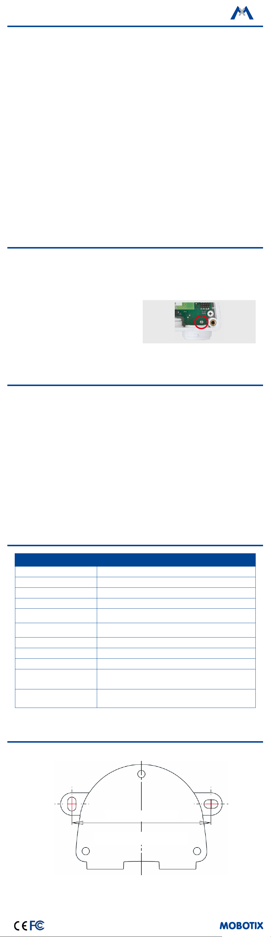
Resetting the MX-Proximity-Box
If the MX-Proximity-Box had been connected to a
dierent camera before and was not deactivated or
reset before detaching, the le LED (operating status)
may ash red aer establishing the connection. In this
case, you need to reset the connected and activated
MX-Proximity-Box to
factory defaults
:
• Remove the box cover.
• Bridge the contact surfaces in the bottom right
corner (red circle in gure) using a screwdriver,
for example (both LEDs are ashing red/blue with
increasing frequency).
• Only remove the bridge if both LEDs of the
MX-Proximity-Box are ashing green on/o 3
times to indicate that the process has nished
successfully.
• Mount the cover back onto the box.
• Set up the MX-Proximity-Box in the camera (see
«Initial Operation of the MX-Proximity-Box»
).
This device is granted pursuant to the Japanese Radio Law (電波法)
This device should not be modied (otherwise the granted designation number will become invalid)