Revison History:
Rev. 1.0: Initial release
VIVOTEK Mounting Accessories
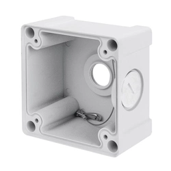
AM-711 Junction Box
Installation Guide
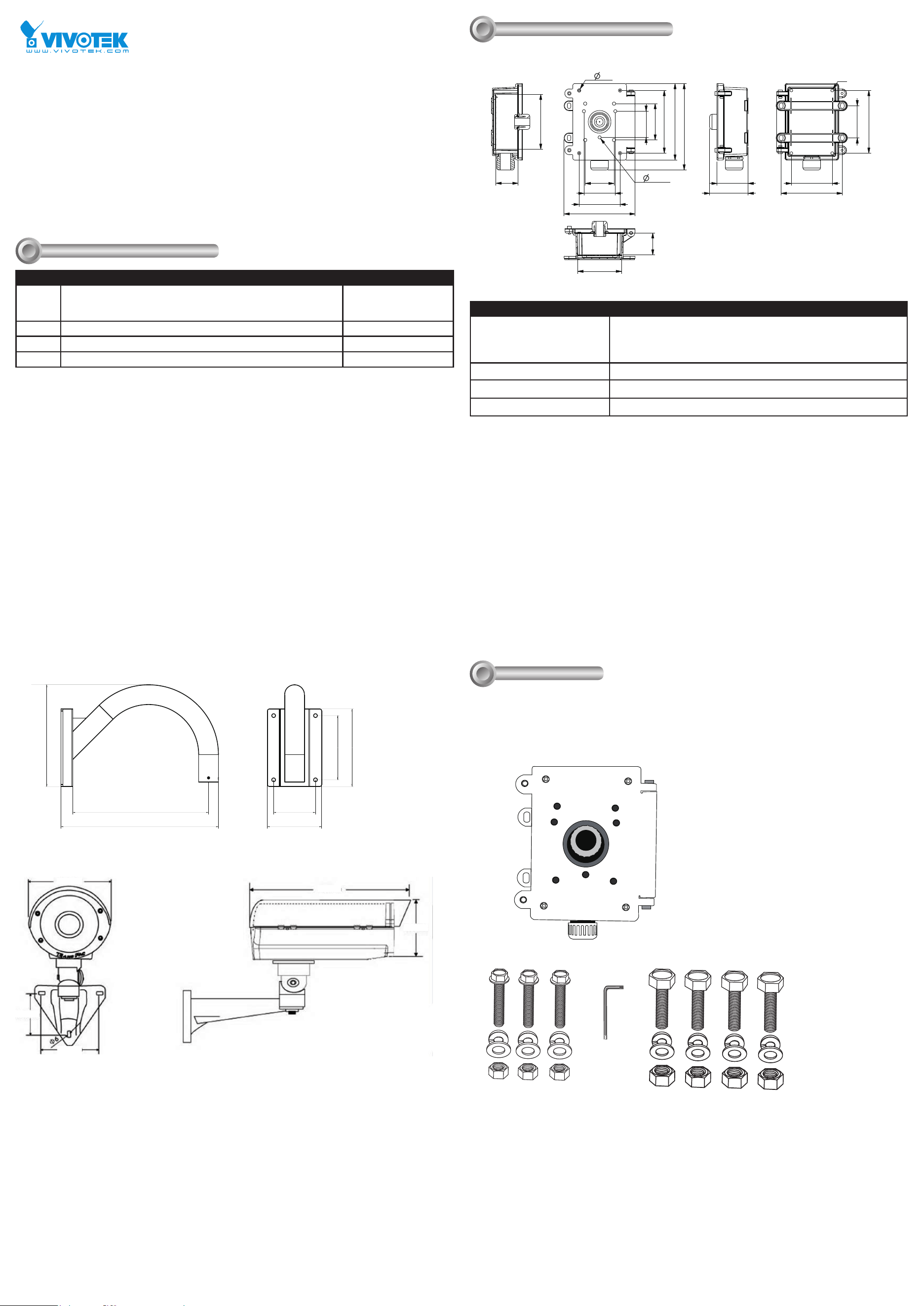
Mechanical Drawings
II
AM-221 Gooseneck
405.8
262.19
140
350 107.8
165.5
200
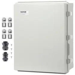
AE20xx Series Enclosure
160mm
68.5mm
83.2mm
425mm
165mm
Installation
III
Compatible VIVOTEK Cameras
I
Type Compatible cameras/brackets Brackets
A AM-212/221,
SD8363E, SD8364E, SD83x4E, SD83x6E, SD8333E, w/ AM-519
(900014900G )
AM-311/411
B AE2000/ AE234/ 235/ 211/ 232/ 233 AM-311/411
C Medium Bullet, see AM-311/411 documents for compatibility. AM-311/411
D Large Bullet, see AM-311/411 documents for compatibility. AM-311/411
AM-711 Junction Box
161,3
85
107,8
165,5
187,6
202
107,8
165,5
96
76
69
82,8
82
58,2
145
115
58,2
8,5
9
228
101,4
M8
SECTION A-A
SECTION B-B
Corresponding part numbers:
AM-711: 900005100G
AM-311: 900002902G (v03)
900002903G (v04)
AM-411: 900003003G (v04)
900003004G (v05)
AM-221: 900014800G
AM-212: 900004202G
Package Contents
Items 1. Junction box
2. Screw set 1 for box type housing
3. Hex wrench
4. Screw set 2 for dome type housing
Box Net Weight 2 kgs
Box Gross Weight 2.3 kgs
Box Dimensions 235 x 244 x 145mm
AM-711 Junciton Box Installation
1
2
3
4
A 3/4" conduit is required for the waterproof connector in the center, and another 1-inch conduit should be
tted to the bottom connector.
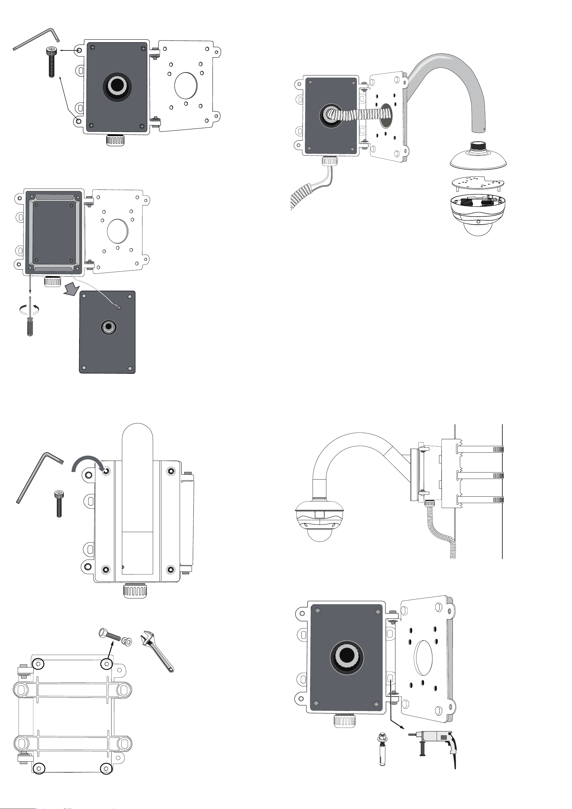
1. Use the included hex wrench to remove the socket head cap screws, and then open the front panel.
2. Use a Phillips screwdriver to loosen and remove the middle plate in the junction box.
Feed cables and install accessories, such as power adaptors and PoE injectors, through the box and the
waterproof connectors on the box.
3. Use the included hex head bolts to secure a gooseneck bracket to the junction box.
4. cables should have been connected and routed through the waterproof connectors. Cable conduits should
also be properly installed for waterproofness.
Please refer to the AM-518/51A Installation Guide for other options.
4. Use the included hex wrench to fasten the socket head screws for the front door.
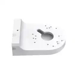
5. Use the 4 mounting holes on the back of the junction box to attach to a pole mount or a corner mount bracket.
See previous discussions for details.
6. You can then attach the junction box, along with the camera, to a pole-mount or corner-mount position. A pole-
mount installation is shown below.
You may also mount the junction box directly to a wall. The mounting holes on the right hand side is accessible
when the front door is opened, and the anchors and screws are user-supplied. .