
2
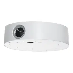
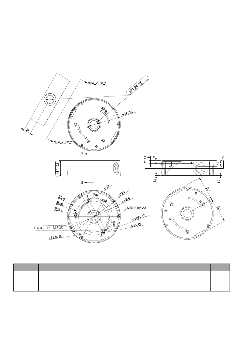
AM-712 Conduit Box Mechanical Drawings
Revision History:
* Rev. 1.0: Initial Release
* Rev. 1.1: Added FD8367-TV, FD8167-T, and FE8180 as the supported models.
* Rev. 1.2: Added corresponding part numbers, and FD8169 as supported model.
* Rev. 1.3: Updated the corresponding part numbers of accessories.
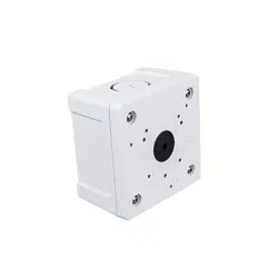
Package Contents
Item No.
AM-712
conduit
box
Conduit box 1
3
English
Physical Description - Use
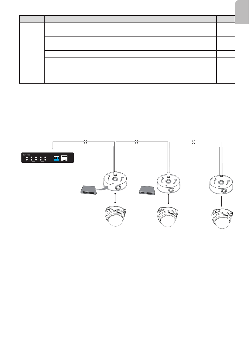
100m 100m 100m
PoE switch
AP-FXC-0210
PoE Extender
1 2
3
4
1 2 3 4
LA N
PoE
UPL INK
PoE
ON
OFF
4xFE PoE + 1xFE Switch
UPLINK
POWER
ON
* The NPT (National Pipe Taper) or PT pipes with male threads are user-supplied.
** The last conduit box does not need to contain a PoE extender.
Item No.
Screw
pack
M3x6 round head w/ washer (nickel and nylok) 7mm; (for securing
dome cameras to the base plate)
5
#6-32 L6 truss head (nickel and nylok) 8mm (for direct installation to a
junction box)
2
Anchors
3
Pan head M4x25, zinc-plated, self-tapping screws (for direct installation
to ceiling)
3
M3x6 pan washer head
2
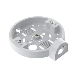
4
Alignment notch
For countersunk head screws
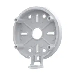
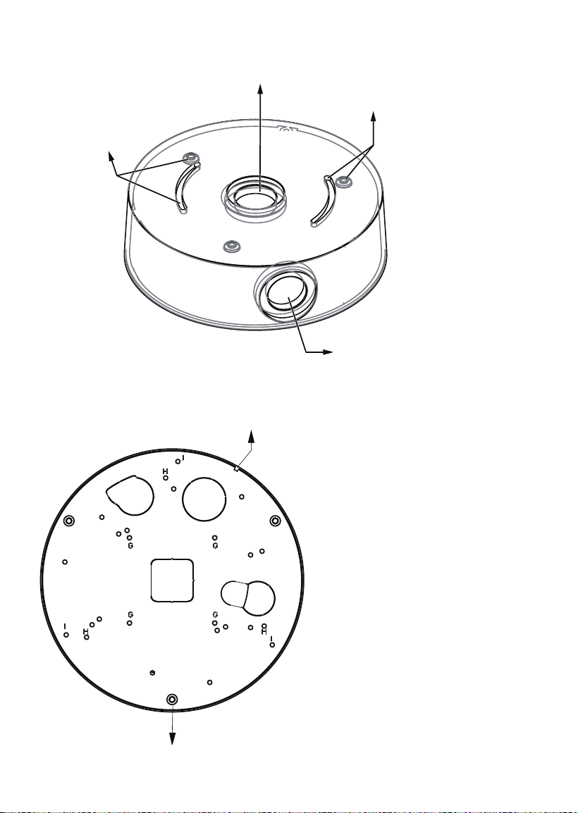
Physical Description - Bottom
Physical Description - Top
For attaching to juction box
For attaching to juction box
For 3/4” conduits
For NPT or PT pipe
5
English
Installation
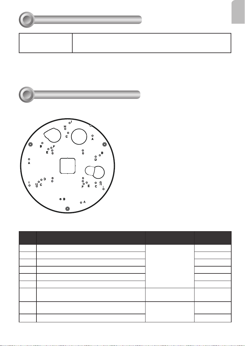
II
Above are the locations of different groups of mounting holes for matching different
cameras:
Hole
Type
Applicable Cameras Screw No. of screws
A
FD8137HV/ FD8154V / FD8164V
M3x6 round head
3
B
FD8137H / FD8154 / FD8164 / FD8169 3
C
FD8131V / FD8133V/ FD8134V
3
D
FD8131 / FD8133 / FD8134 2
E
FD8151V / FD8152V 2
F
FD8136 / FD8166
2
G
FE8180 M3x6 pan washer
head
2
H
FD816BA-HF2, FD816BA-HT, FD8182-F2,
FD8182-T, FD9171-HT, FD9181-HT
M3x6 round head
3
I
FD8367-V / FD8367-TV / FD8338-HV
3
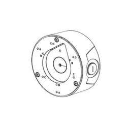
Mounting Hole Denitions
Compatible VIVOTEK Cameras
I
Fixed Dome series
FD8152V, FD816BA-HF2, FD816BA-HT, FD8182-F2, FD8182-T,
FD9171-HT, FD9181-HT, FE8180, FD8166A, FD8166A-N
You may also refer to VIVOTEK's website for the list of supported models. Support for other models can
be available through time.

6
NOTE:
1. The AM-522 is necessary when installing the AM-712 mounting cap to VIVOTEK's
standard mounting options such as AM-212 (wall mount bracket) and AM-221
(gooseneck).
The AM-522 features the mounting option for NPT pipes only.
2. Route cables before you secure the accessories to a wall.
3. For details on the cable connections with each camera, please refer to their Quick
Installation Guide.
For cabling and conguration details with each network camera, please refer to their
documentation.
7
English
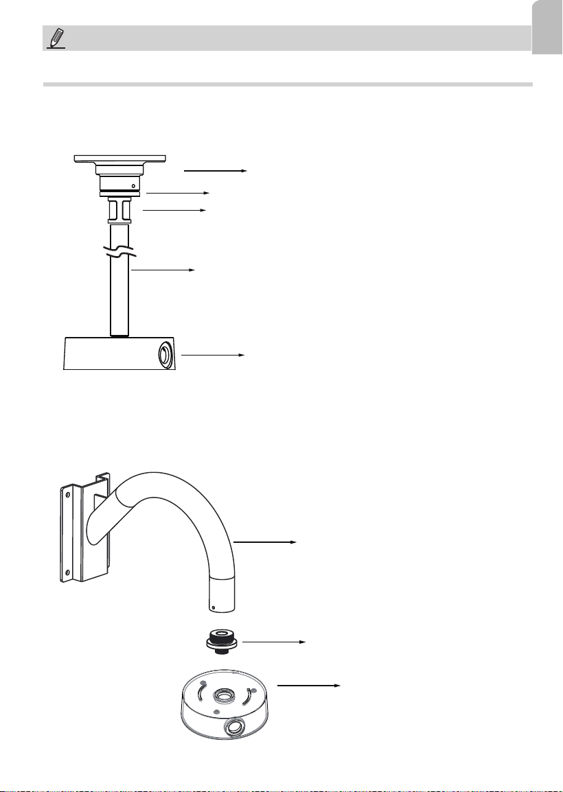
Conguration - Pendant Pipe
3/4” pendent pipe
AM-712
AM-522 adapter
AM-118 pendant head
3/4” female adapter
Note: The 3/4" female adapter and pendant pipes are separately purchased.
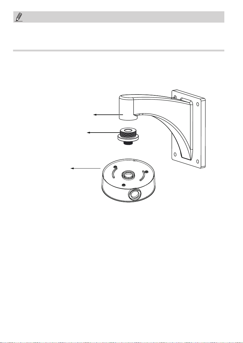
Conguration - Gooseneck
AM-712
AM-522 adapter
AM-221 gooseneck
NOTE:
The following mount types do not apply to PT pipes.
8
NOTE:
When installing the mounting cap, take note that the orientation of the mounting cap can
affect the camera's shooting direction. You may need to disconnect the conduit box from
the NPT pipe, rotate, and re-install it for the best orientation.
Conguration - Wall Mount
AM-712
AM-522 adapter
AM-212 Wall-mount bracket
9
English
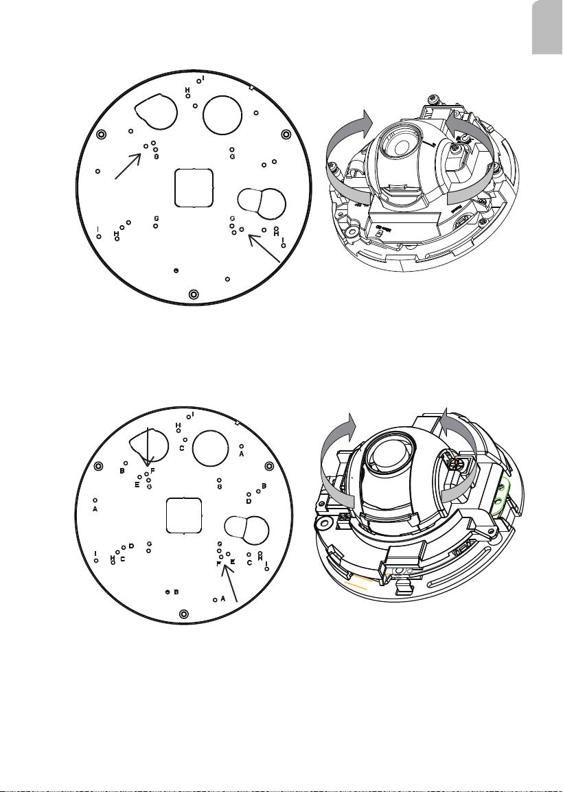
Refer to the matching table on page 4 for the mounting hole information for your camera.
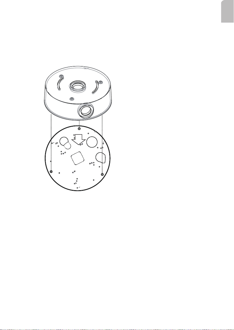
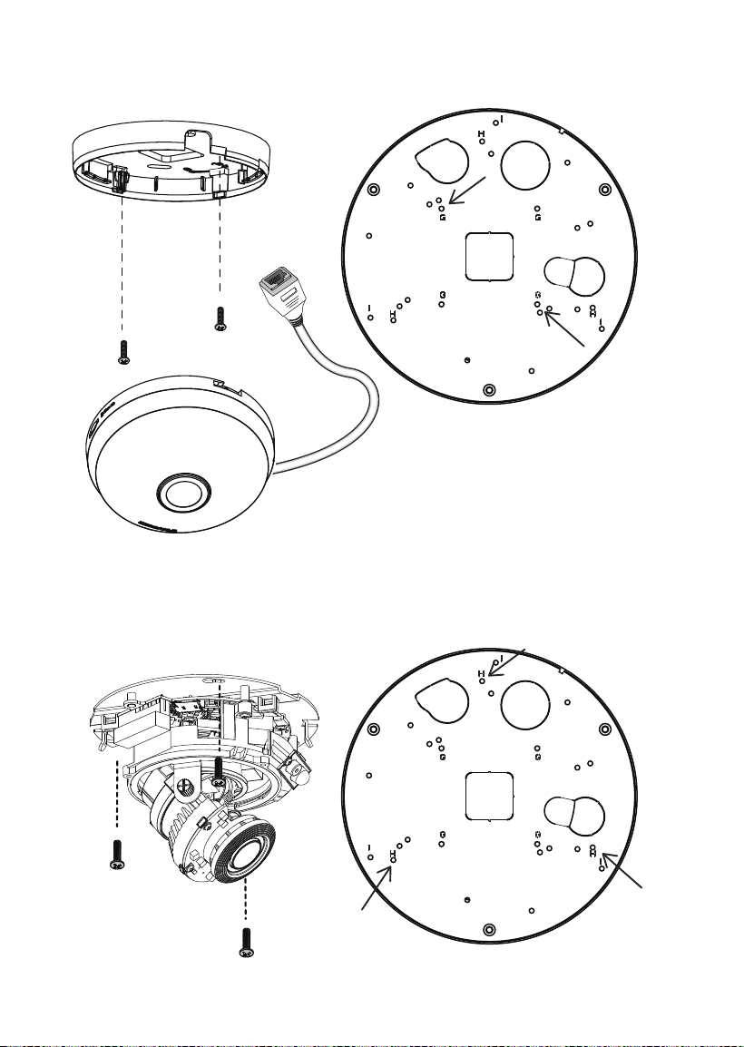
III-1. Installing Camera to Conduit Box
1. Remove the base plate from the bottom of the conduit box.
2. You can route cables through other accessories before you install cameras to the base
plate.
3. Orient and install the camera to the base plate (to the side with printed characters).
4. Connect cables to the camera.
5. Install the base plate to the conduit box.
6. Proceed with initial setup such as enabling network access, focus tuning, or zooming.
When done, secure the outer dome cover.
10
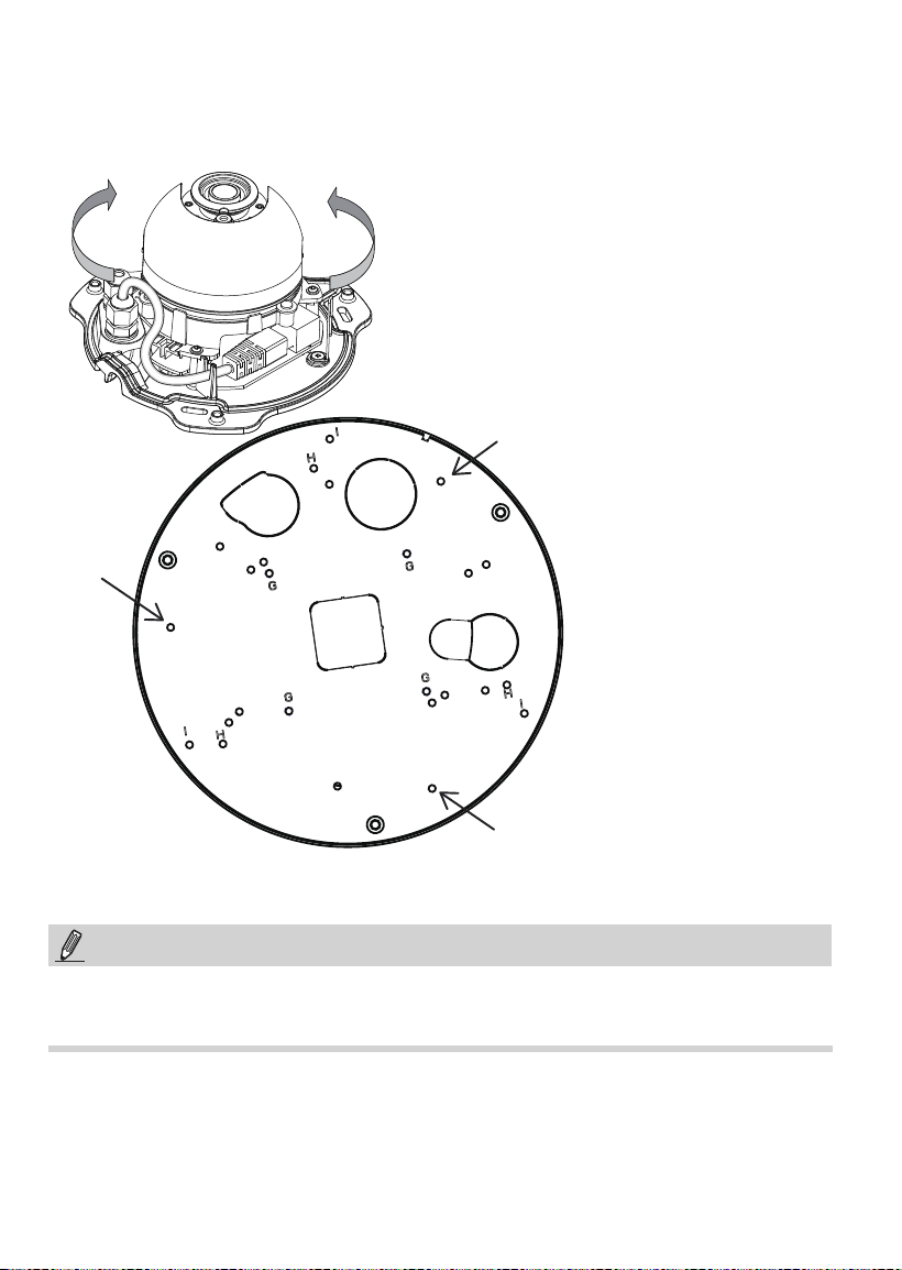
A
A
A
The A Screw Holes: FD8154V / FD8137HV / FD8164V
Some installation samples are shown below:
NOTE:
Orient the camera so that cables coming out from the camera can pass through the
cabling hole on the base plate.
11
English
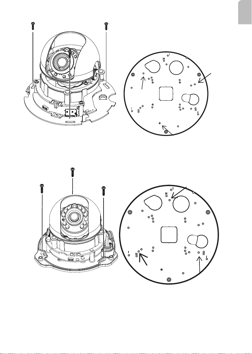
B holes
B
B
B
M4X12 Screws
C holes
C
C
C
The B Screw Holes: FD8154 / FD8137H / FD8164 / FD8169
The C Screw Holes: FD8131V / FD8133V / FD8134V
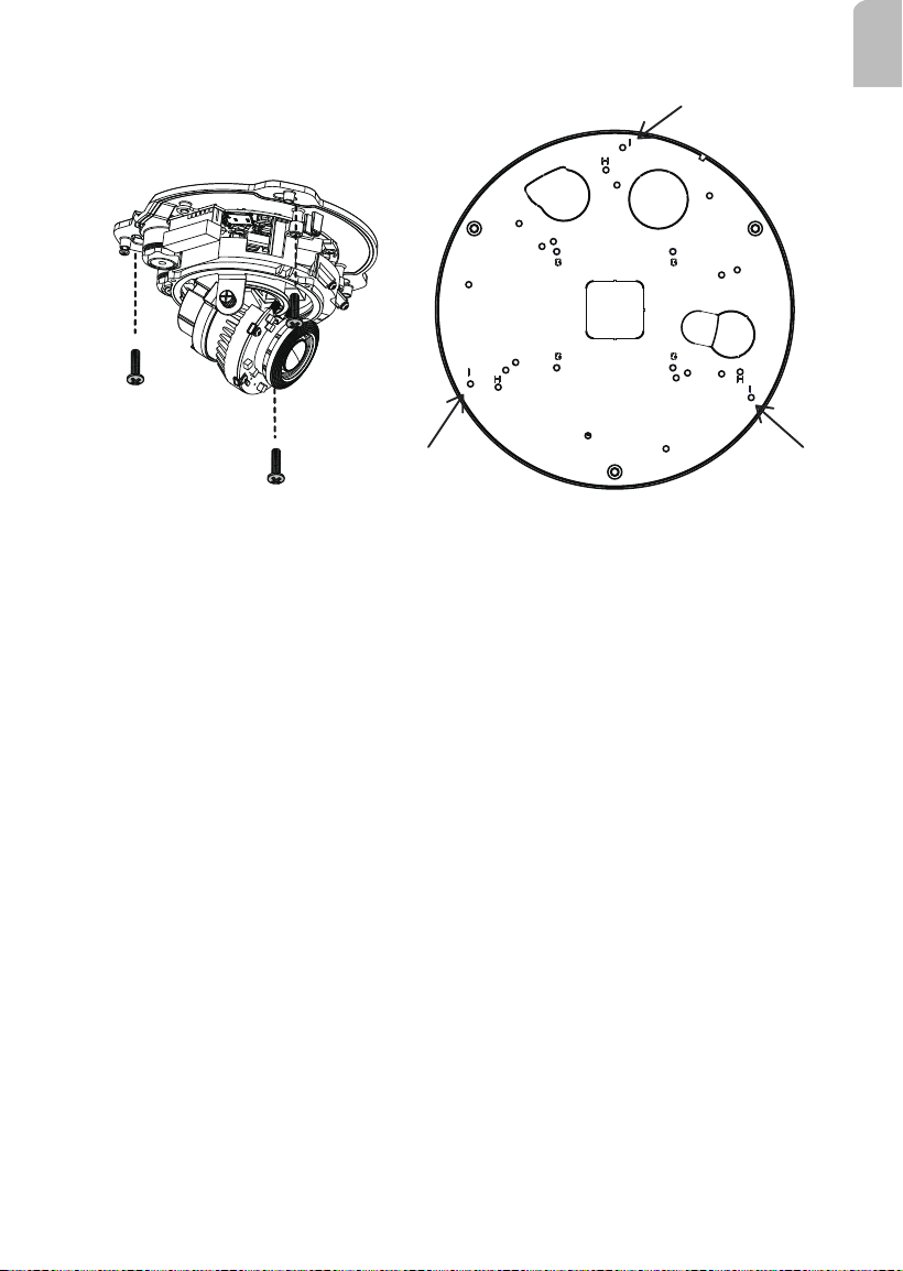
12
The D Screw Holes: FD8131 / FD8133 / FD8134
D
D
13
English
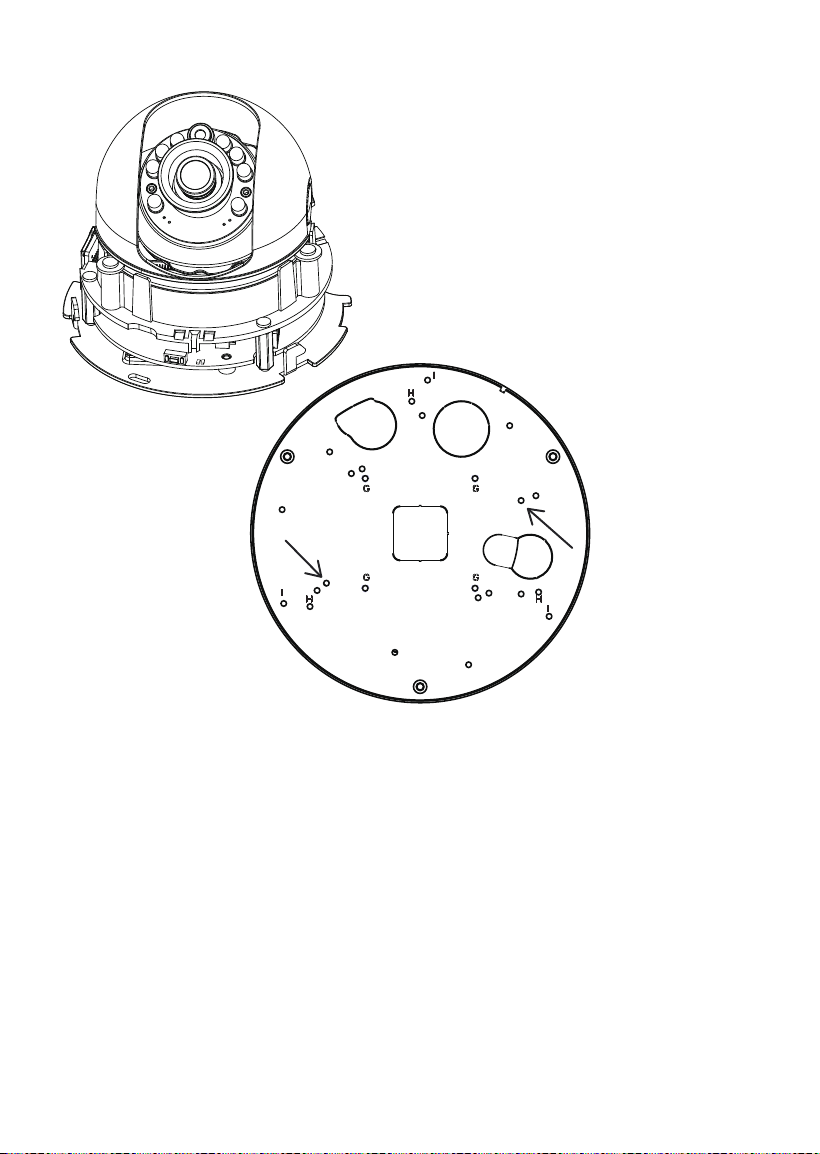
The E Screw Holes: FD8151V / FD8152V
E holes
E
E
The F Screw Holes: FD8166A / FD8166A-N
F holes
14
M3X6 Screws
G holes
The G Screw Holes: FE8180
M3X0.5 L6 Screws
H holes
The H Screw Holes: FD816BA-HF2, FD816BA-HT, FD8182-F2,
FD8182-T, FD9171-HT, FD9181-HT
15
English
M3X0.5 L6 Screws
I holes
The I Screw Holes: FD8367 and 8338 Series
16
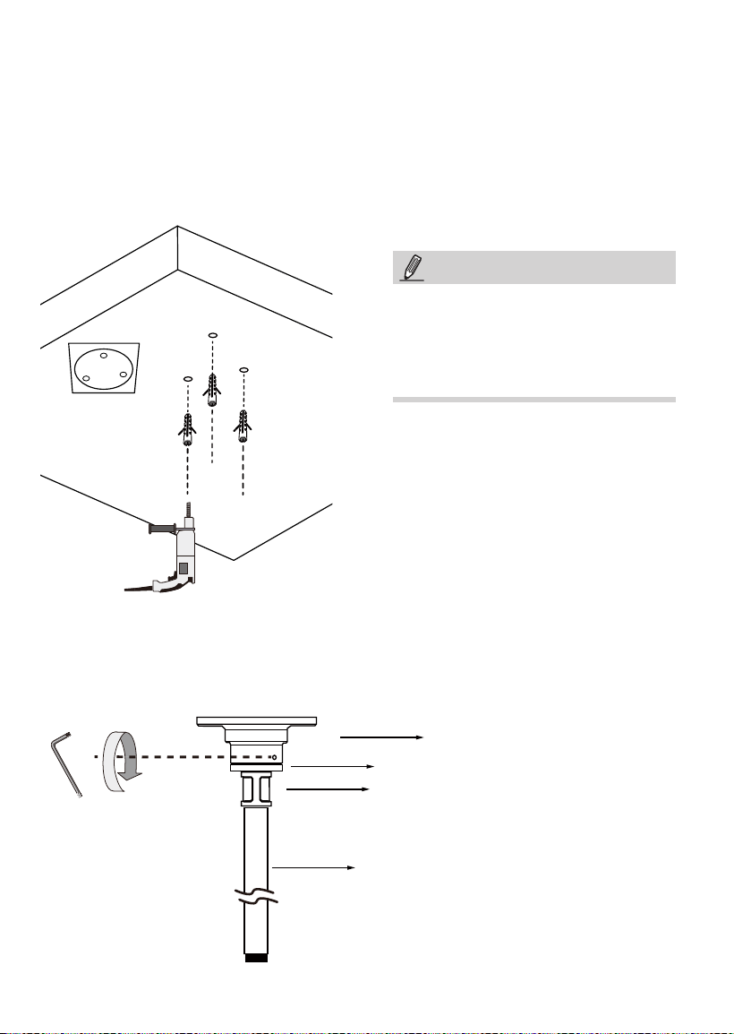
III-2. Installing the Pendant Head and Pipe
3/4”pendent pipe
AM-522 adapter
AM-118 pendant head
3/4” female adapter
Below are the sample procedures using a pendant head and pendant pipe:
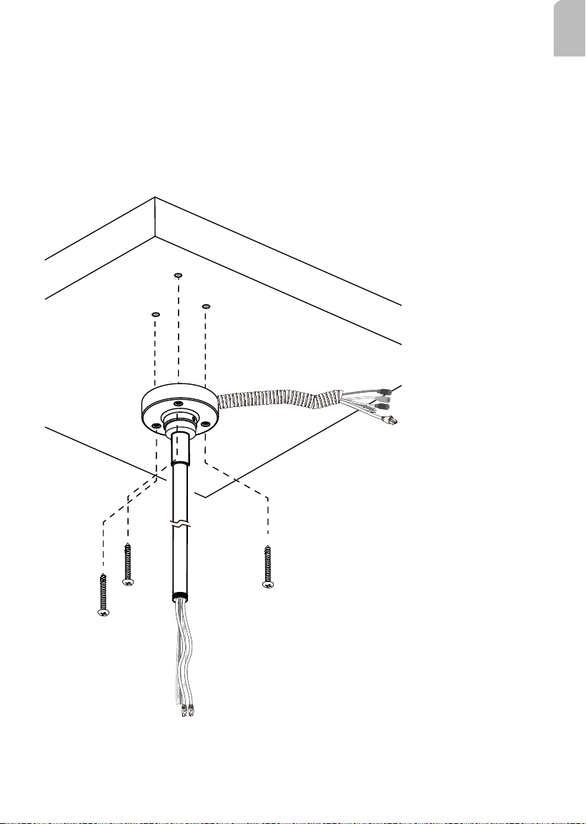
1. Determine a hard surface ceiling location, and use the alignment sticker to mark the
positions where holes will be drilled to secure the pendant head. Hammer the anchors
into the ceiling.
Note that mounting holes should be 10mm in diameter and 60mm deep. The included
screws are M6.2 x75mm.
2. Install an NPT or PT male thread pipe (length determined by installers) by turning it
clockwise to the pendant head, and secure the connection using an included 3mm hex
wrench.
NOTE:
This mount type applies to NPT pipes
only.
For NT pipes, xture on the other end
should be handled by users.
17
English
3. Route Ethernet cable and other wires through the pendant head. You may apply a 1
inch conduit.
Note that when routing Ethernet cables, please make sure you have tagged the cables
as PoE input (coming from a PoE switch), or PoE output (one that transmit data and
power to the next conduit box).
4. Secure the pendant head to ceiling by driving screws through its mounting holes.
Depending on the length of your cables, you may need the help from your colleague for
holding the components.
Pendant Head Cables
18
Connector side
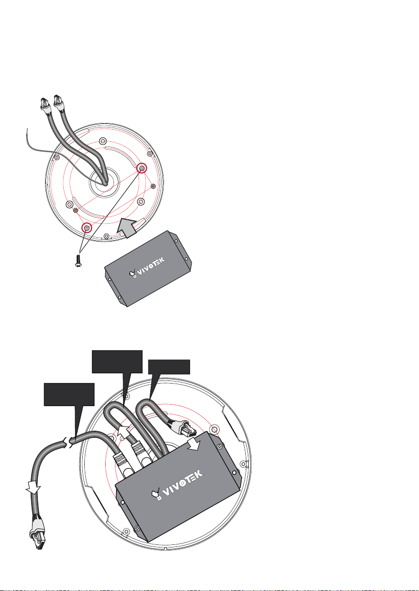
1. Pull cables through the NPT pipes and then the conduit box.
2. Install the conduit box to the NPT pipe.
3. When done, install the PoE extender by driving 2 screws to the conduit box, its
connector side facing the inside of the box.
III-3. Installing the Conduit Box and PoE Extender
4. In a cascade topology, there should be 2 Ethernet cables in the pipe. One is used as
PoE input, the other as the out port to the next conduit box.
PoE IN
PoE OUT
to another conduit
box
PoE OUT
to camera
You may use cable tags to identify PoE cables.
19
English
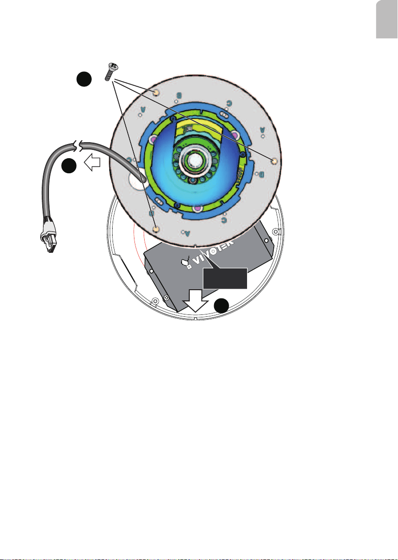
5. Pull the Ethernet cable (and/or I/O wires) through the cabling hole on the base plate.
6. Orient the alignment notch with the tab on the conduit box.
7. Secure the base plate along with the camera to the conduit box.
Alignment
Notch
5
7
6
To Camera LAN port
8. Install the camera's dome cover.
9. Proceed with initial setup such as enabling network access, focus tuning, or zooming.

20
This page is intentionally left blank.