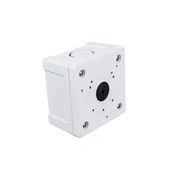
IMJTV-JB
Conduit Box
Installation Guide
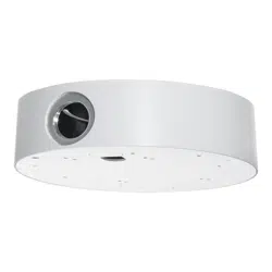
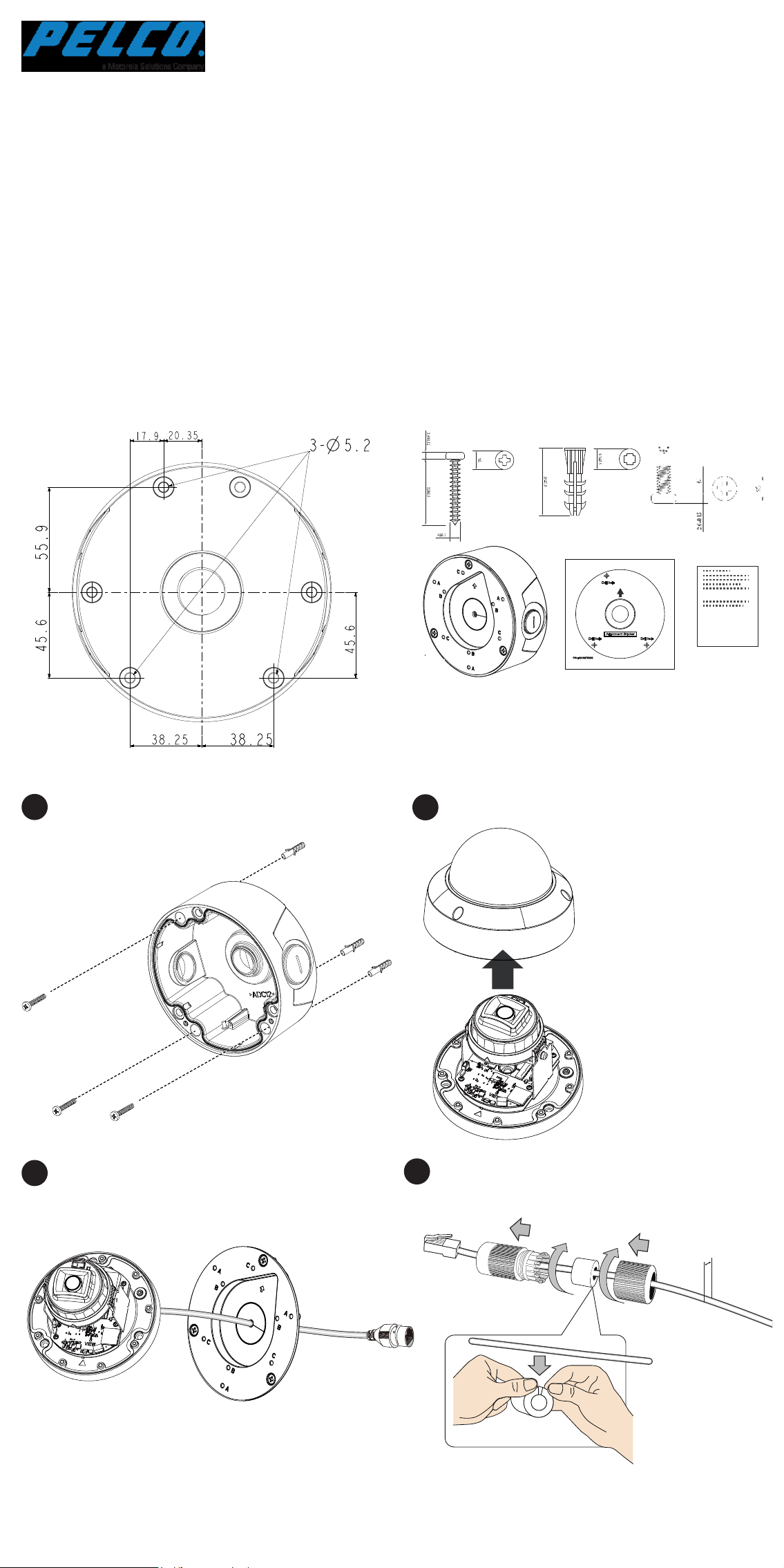
Mounting Dimensions
A 3/4" conduit is required for routing the cables with waterproof
connection.
Remove the top cover.
Install the cable gland and pass cables through it.
Loosen and remove the camera top cover. (Using one of
the supported cameras as an example)
Pass the camera's Ethernet cable through the center hole of
the box and the rubber seal.
1
2
4
5
6
7
8
Install the camera using the corresponding mounting holes.
C6693M
x3
x3
x3
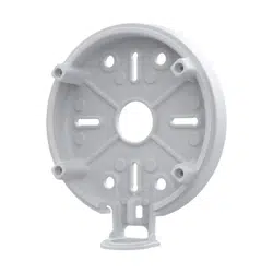
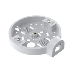
Package Contents
Mounting hole locations:
A: IMV Series
B: ITV Series
C: IJV Series
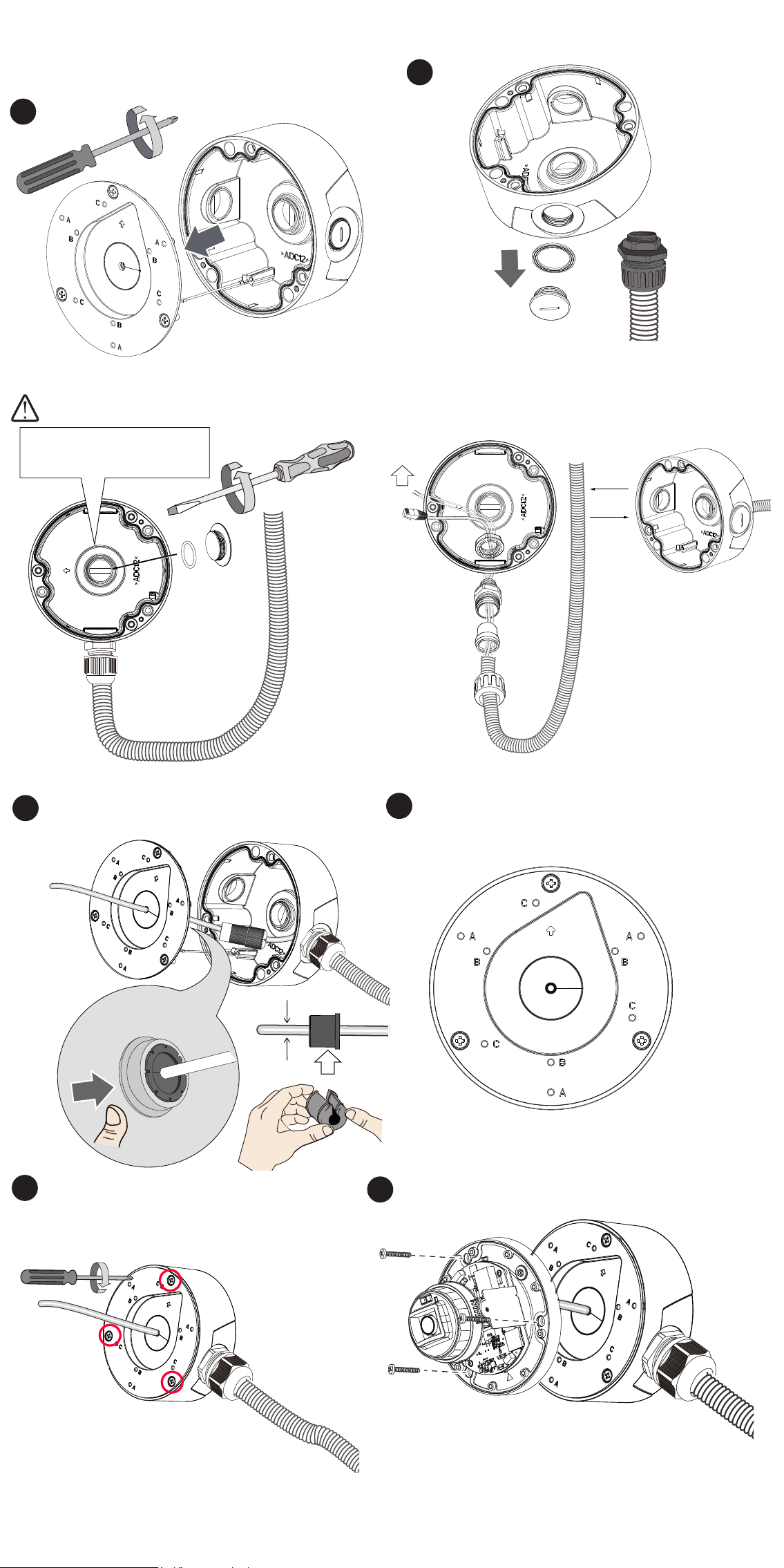
5.5 ~ 6.4mm
5 ~ 6.3mm
Make sure the rubber seal is properly installed to the center
hole. The outer rim of the seal must be through and cover the
edge of the hole.
10
Install the waterproof components of the cable gland to your
Ethernet cable following the QIG of your camera. The cable
gland will be placed within the protection of the box.
If using the bottom hole,
seal the center hole.
OR
3/4”
9
Secure the top cover by fastening 3 cross-head screws.
Attach the included alignment sticker to a preferred position.
Drill holes on the wall and install the junction box. If space
behind the wall allows, you may also pass cables through the
wall.
3
Installation
IMJTV-JB
Conduit Box
Installation Guide
Mounting Dimensions
A 3/4" conduit is required for routing the cables with waterproof
connection.
Remove the top cover.
Install the cable gland and pass cables through it.
Loosen and remove the camera top cover. (Using one of
the supported cameras as an example)
Pass the camera's Ethernet cable through the center hole of
the box and the rubber seal.
1
2
4
5
6
7
8
Install the camera using the corresponding mounting holes.
C6693M
x3
x3
x3
Package Contents
Mounting hole locations:
A: IMV Series
B: ITV Series
C: IJV Series
5.5 ~ 6.4mm
5 ~ 6.3mm
Make sure the rubber seal is properly installed to the center
hole. The outer rim of the seal must be through and cover the
edge of the hole.
10
Install the waterproof components of the cable gland to your
Ethernet cable following the QIG of your camera. The cable
gland will be placed within the protection of the box.
If using the bottom hole,
seal the center hole.
OR
3/4”
9
Secure the top cover by fastening 3 cross-head screws.
Attach the included alignment sticker to a preferred position.
Drill holes on the wall and install the junction box. If space
behind the wall allows, you may also pass cables through the
wall.
3
Installation
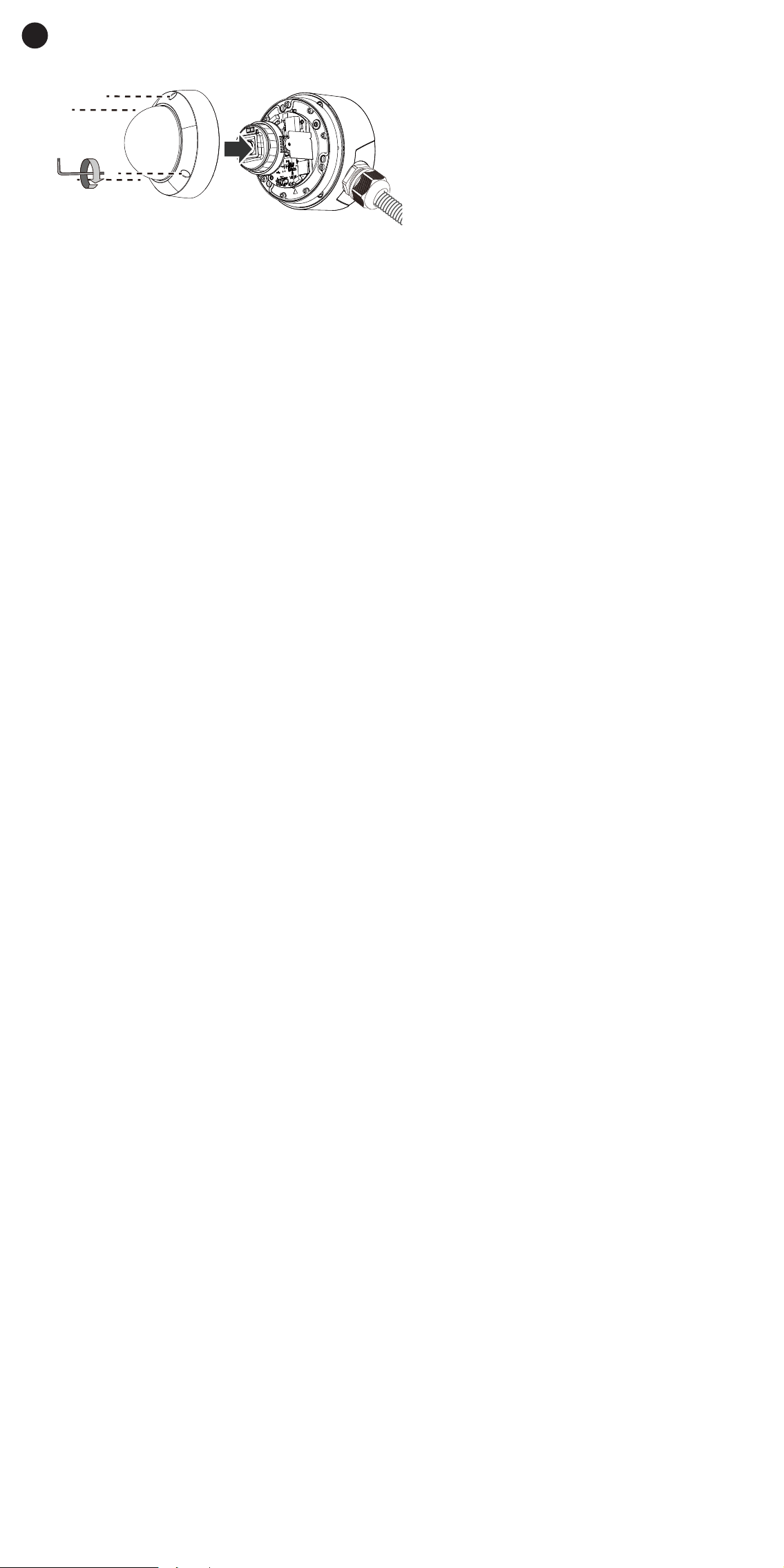
Secure the camera lower dome.
Open a live view page on the camera's web user interface and
point the camera to obtain the desired eld of view.
T10
11
Pelco, Inc.
625 W. Alluvial, Fresno, California 93711 United States
USA & Canada Tel (800) 289-9100 Fax (800) 289-9150
International Tel +1 (559) 292-1981 Fax +1 (559) 348-1120
www.pelco.com