
2

3
CONTENTS
Initial Operation and Configuration 5
Initial Operation 6
Adding Door Stations and Cameras to MxDisplay 9
Setting Up MxDisplay 11
The MxDisplay – Overview 17
At a Glance 18
The Main Menu 19
The Camera Bar 22
The Live View 24
Event Overview and Event Lists 28
The Player 30
All Settings at One Location 34


55
1
Initial Operation
and Conguration

6
Initial Operation
Make sure that the door stations and cameras are using a current camera so-
ware release 4.3.0 or higher. If this is not the case, upgrade to the most recent
soware. See "Compact Guide: Firmware Update" under www.mobotix.com >
Support > Manuals > Soware > Compact Guide for more information.
The MxDisplay is delivered with the newest soware. If a new soware release
has been published in the meantime, you can update the MxDisplay soware
using a browser. To update the soware, start a browser, enter the IP address
of the MxDisplay unit (user admin, password meinsm) and then select Update
System Soware.
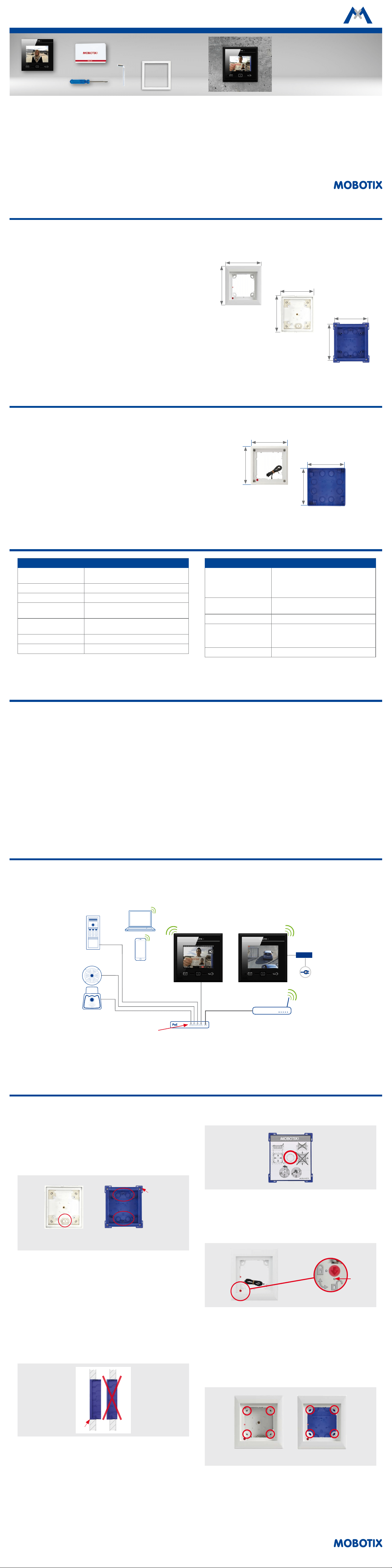
Connect MxDisplay
If you are using a network cable for the network connection and the power
supply of the MxDisplay, connect the network cable to the PoE switch. Switch
on the power supply. If the network connection uses WiFi and a two-wire cable
supplies the power, simply connect the two-wire cable and start conguring the
MxDisplay. Next, set up the WiFi client of the MxDisplay unit (see section Select
the WiFi Mode).
7
Adding a Door Station
If you have already integrated the door station, you can skip this section and
continue with the section Adding Door Stations and Cameras to MxDisplay.
Setting up the door station follows the steps outlined in Chapters 2 to 4 of the
"T25 System Manual Part 2". The T25 System Manual is available at
www.mobotix.com > Support > Manuals > IP Video Door Station.
Overview over the most important steps:
1. Power and Network
Make sure that all devices are connected to the network and that the power
supply has been established.
2. Execute Auto Conguration
Carry out the auto conguration at the door station (see Section 2.1.3 in
the "T25 System Manual Part 2"). When using several door stations, choose
one door station as a master and then carry out the auto conguration on
that door station. The auto conguration is completed by entering the
Super PIN at the access modules (KeypadRFID or BellRFID).
3. Congure Access Modules
The access modules of the system will now be set up one by one. This
includes training the RFID cards, entering the contact/people/PIN numbers
(if applicable) and conguring the bell buttons on the BellRFID modules
(see sections 2.2 and 2.3 in the "T25 System Manual Part 2").
8
4. Reboot the MxDisplay
Aer the auto conguration has nished, the MxDisplay will reboot auto-
matically and show the date and time view of the standby mode.
9
Adding Door Stations and Cameras to MxDisplay
If the initial setup of the door station has been completed, you can add the
door stations and cameras to the system.
1. Open the Installation Wizard
Aer starting the MxDisplay, it automatically shows the date and time in
stand-by mode. Tap on the view and select the Installation Wizard.
2. Complete the Installation Wizard
Click on in the upper right corner and complete the dialogs by speci-
fying the following information:
• Language:
The factory default language is English. Select the desired language. This
will change the language of the user interface as well as the default mailbox
messages.
• Camera List:
Add the door stations and/or cameras that are not yet on the list:
–
Tap on and then on to start the automatic search for cameras and
door stations.

10
– Select the desired video sources and tap on .
– Enter the camera access data (user name and password of a camera
administrator). Important: You have to enter the Super PIN (the number
you entered during auto conguration) as the password for the door
stations.
• Camera Conguration
Use this dialog to deactivate the auto conguration and dene any installed
door sensors and door lock sensors on all door stations. You should activate
recording on all cameras and door stations and adjust the remaining set-
tings to match your requirements.
• Assign Bells
MxDisplay recognizes the bell buttons of the connected door stations and
lists the buttons for each door station. Select the bell buttons that should
trigger the doorbell at this MxDisplay by activating the corresponding slid-
ers.
Click on
to close the Installation Wizard.
11
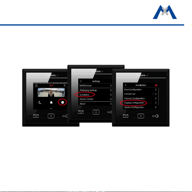
Setting Up MxDisplay
Next, congure the MxDisplay devices. Tap on Settings > Installation > Display
Conguration in the main menu (see section The Main Menu) to do so.
Assign Bells
If you did not assign the bell buttons in the Installation Wizard, you should do
this now (see above).
12
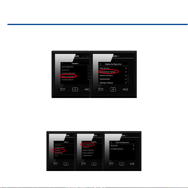
Assign Signal Inputs/Outputs
If you have connected a temperature sensor, tap on Temperature Sensor and
select the corresponding sensor.
In case you have connected an apartment doorbell, a door sensor, a door lock
sensor and a door opener, open the Door Conguration under Settings >
Installation, tap on Floor Call (see section Floor Call) and assign the signal
inputs and the output accordingly.
13
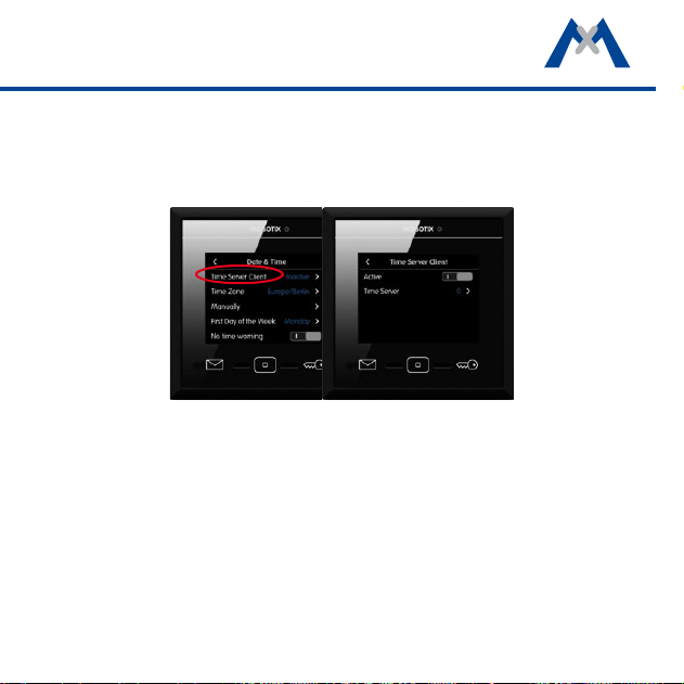
Set the Date and Time
MxDisplay and all door stations and cameras should always use the same time.
You can use a time server for this purpose, since it synchronizes the time of all
attached devices.
1. In the Display Conguration, tap on Date & Time > Time Server Client
and activate the slider.
2. Tap on Time Server and select a time server or manually add a time server.
3. Return to the Date & Time submenu and select the appropriate time zone.
The system can now automatically switch between daylight savings time
and regular time.
4. If no time server is used, you can also
set the date and time manually
.
Tap
on Manually and set the date and time.
14
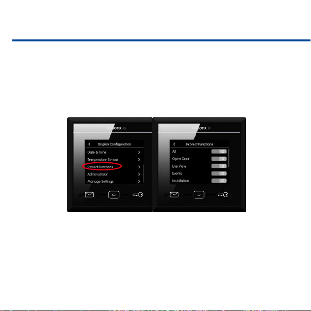
Protect Functions
It is possible to protect (i.e., lock) specic functions or even all functions. To do
so, activate the sliders of the corresponding functions. Once protected, the users
can access these functions only aer entering a PIN. To assign the rights for exe-
cuting specic functions for users and their PINs, open the Access Control dia-
log (see section Access Control).
Change the Administrator PIN
By default, the administrator PIN has been set to "0202". If you want to change
this PIN, open the Display Conguration, click on Administrator, enter the
factory default PIN and then enter the new PIN.
15
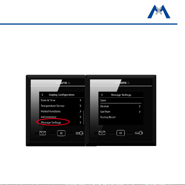
Copy Settings
When using several MxDisplay units, you can copy the settings from this device
to other devices. On every other device, open Display Conguration and tap
on Manage Settings > Get from. Select the desired MxDisplay device.

16

1717
2
The MxDisplay –
Overview
18
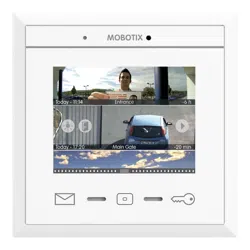
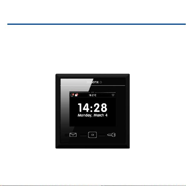
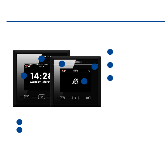
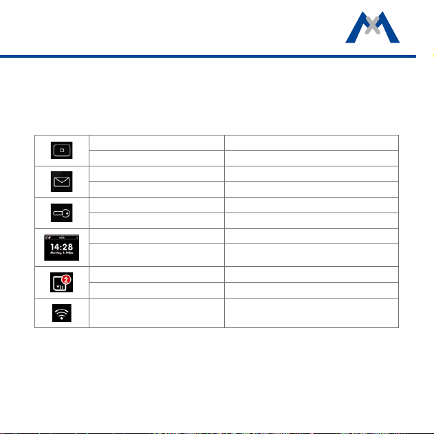
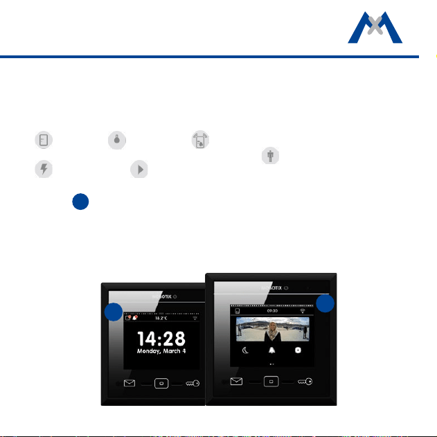
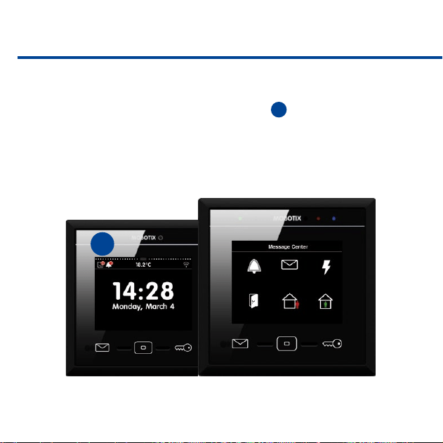
At a Glance
MxDisplay automatically shows the date and time in stand-by mode aer start-
ing. In stand-by mode, you see at one glance:
1
The time and date of
the selected time server.
2
The current tempera
-
ture of the selected sensor.
3
If, when and how many
visitors have rung the
doorbell and how many
events have occurred. Tap
on the corresponding icon
to open the event over-
view, which lists the event
images according to their type.
4
The WiFi status.
5
The bell muting status. In this case, the display alternates between the
bell status and stand-by mode.
1
2
3
4
5
19
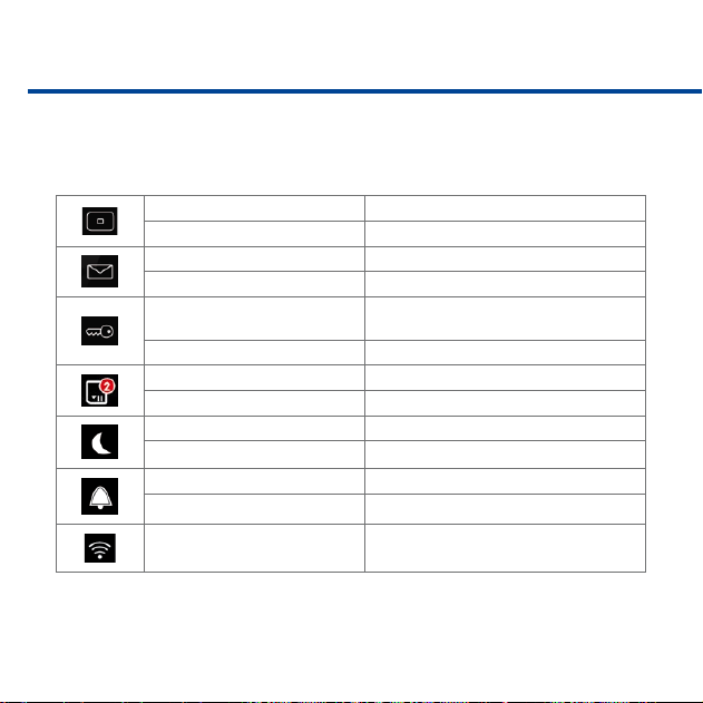
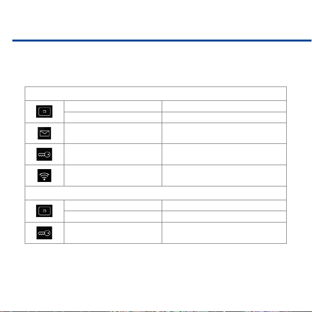
Overview – Shortcuts of the Stand-By Mode
If the MxDisplay shows the stand-by mode, you can tap or tap and hold the
dierent buttons and icons to quickly access the following functions without
having to open the corresponding menu.
Tap on Home button Open main menu
Tap and hold Home button Open screensaver settings
Tap on Letter button Open mailbox event list
Tap and hold Letter button Open event overview
Tap on Key button Open Live view of rst camera in camera list
Tap and hold Key button Open door of connected door station
Tap on view Open main menu
Tap on view and hold Open time and date settings
Tap on Event icon Open event overview
Tap and hold Event icon Set event lter
Tap and hold WiFi icon Open WiFi settings
20
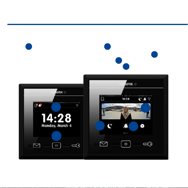
The Main Menu
From stand-by mode, you can enter the main menu either by tapping on the
view
1
or by tapping on the Home button
2
.
In the main menu, you can activate the Do not disturb function
3
(for all
connected devices) and the Mute bell function
4
(only for this device). In
addition, the main menu shows the reference image
5
of the rst camera in
the camera list.
2
1
3
4
5
21
You can select cameras from the camera bar
6
by opening the bar and tapping
on the camera you want to see.
7
shows the dierent camera statuses,
8
indicates new events and tapping on
9
opens the settings.
The Settings include the basic settings as well as all settings required in daily
use – from bell behavior to camera conguration and access control.
6
7
8
9
22
Overview – Shortcuts of the Main Menu
The main menu also provides shortcuts to dierent functions by tapping or
tapping and holding the dierent buttons and icons.
Tap on Home button Stand-by mode
Tap and hold Home button Create custom view(s)
Tap on Letter button Open mailbox event list
Tap and hold Letter button Open event overview
Tap on Key button
Open Live view of rst camera in camera
list
Tap and hold Key button Open door of connected door station
Tap on Event icon Open event overview
Tap and hold Event icon Set event lter
Tap on Moon icon Activate "Do not disturb“
Tap and hold Moon icon "Do not disturb“ function: Congure ringing
Tap on Bell icon Mute bell
Tap and hold Bell icon Open audio settings
Tap and hold WiFi icon Open WiFi settings
23
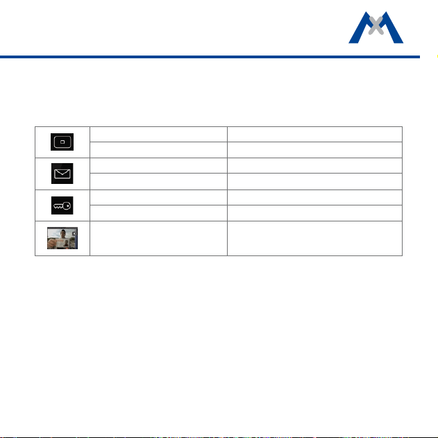
The Camera Bar
The camera bar shows the preview images of all connected door stations and
cameras. You can operate one camera using the controls while still keeping an
eye on the other cameras. The controls have the following meanings:
open door, switch lights, activate walk-through message (a sound
plays when opening a door with door sensor), open mailbox messages,
open event list, open Player.
The camera bar is available in stand-by mode and in the main menu. Pull down
the bar
1
to see the camera bar. If you tap into one of the preview images,
the view changes to show the live image from the corresponding camera (see
section The Live View).
1
1
24
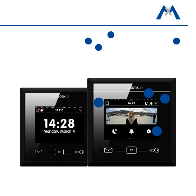
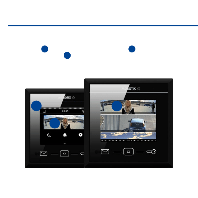
The Live View
To see the live view of a camera, you can either tap on the camera image in the
main menu
1
or you can pull down the camera bar
2
and tap on the image
of the desired camera
3
.
2
1
3
25
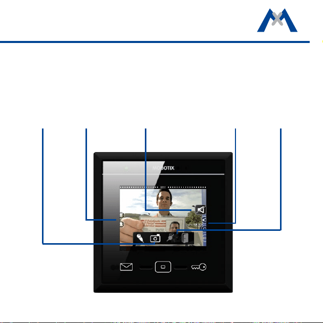
The live view shows the live image of the selected camera; you can use the
sliders to control the camera: Sliders are used to change the speaker volume,
the image brightness, to select precongured image sections, adjust the volume
of the ring tone as well as the ambient noise level, start a snapshot recording,
talk to visitors at the door, open the door and switch lights. To show the controls,
tap on the camera image.
Instant
recording
Brightness,
image sections
Intercom
Volume,
ring tone
Open door,
switch lights

26
Live: Ringing
A ringing door bell will immediately show the live image of the door camera
with an icon to start the conversation.
Live: Intercom, Open Doors and Switch Lights
To speak to a visitor at the door, tap on the large speaker icon. This activates
the door intercom. If you do not want the visitor to hear you, tap on the live
image to see additional icons, then tap on the microphone icon. To close the
audio connection, tap on the speaker icon. To open the door, tap on the Door
icon and to switch the lights, tap on the Light icon (if this camera can switch
lights).
Live: Selecting Other Cameras and Detail View
Tap on the Key button to show a dierent camera. Double-tapping into the live
image shows an enlarged detail view. A second double-tapping returns to the
regular view.
The camera list can show other cameras than the cameras you see when click-
ing on the Key button. Open the camera list, tap and hold the Home button to
dene the contents of the camera list as well as the “favorites“ that are shown
when tapping on the Key button.
27
Overview – Shortcuts of the Live View
The Live view also provides shortcuts to dierent functions by tapping or tap-
ping and holding the dierent buttons and icons.
Tap on Home button Stand-by mode
Tap and hold Home button Open camera conguration
Tap on Letter button Open mailbox event list
Tap and hold Letter button Open event overview
Tap on Key button Goto next camera live image
Tap and hold Key button Open door of connected door station
Tap on view Show controls
28
Event Overview and Event Lists
New events (missed ringing and all other events) are indicated by a red counter
at the event icons in the top le corner of the view
1
. Tap on the icons to open
the event overview. The event overview shows all events grouped by event type:
Ringing, mailbox messages, all other events, door opened, access denied and
access granted.
1
29
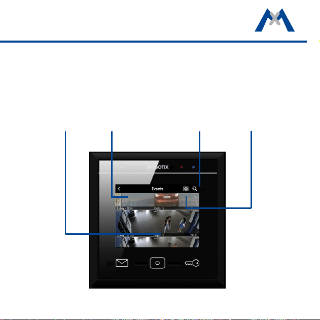
A red counter at the event type indicates the number of new events detected.
Tap on the event type to show the event list. It displays the recorded events
with a preview image, the date and time of the event and the camera name.
Note that you can show the event images not only as a list, but also as single
images. To do so, tap on the List/Single Image icon. You can limit the displayed
event images by selecting specic cameras and time ranges. Tap on the Search
icon, select the camera(s) and the time range, then tap on Search.
Event type
Event Images
Search
function
List/single
image
30
Overview – Shortcuts of the Event Overview and the Event List
The event overview and the event list provide shortcuts to dierent functions
by tapping or tapping and holding the dierent buttons and icons.
Event Overview
Tap on Home button Open main menu
Tap and hold Home button Acknowledge all events
Tap on Letter button Open mailbox event list
Tap on Key button
Open Live view of rst camera in camera
list
Tap and hold WiFi icon Open WiFi settings
Event List
Tap on Home button Open event overview
Tap and hold Home button Open Settings menu
Tap on Key button
Open Live view of rst camera in camera
list
31
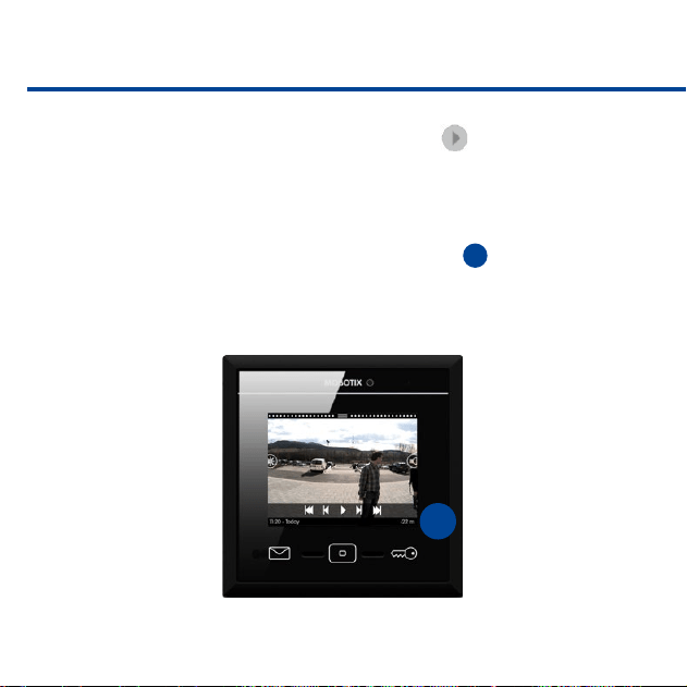
The Player
You can open the player either from the Event List or from the Camera List.
The player will show the recordings either by event type or by camera, depend-
ing on where you opened the player. If you tap on an event image in the event
list, you can play back/fast forward/rewind the recordings to the events of this
event type in the player.
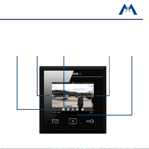
First event
Play
Brightness
Volume
One image
forward/
backward
32
If you open the camera list and then tap and hold one of the live images, dif-
ferent controls for this camera appear. Tap on Play to open the player. In
the player, you can play back all recordings of this camera, you can fast forward
and rewind them.
Note that the player always provides quick access to the last four event images –
starting from the current recording. This is done using the Event Info bar at the
bottom of the player. The event info bar shows the time
1
since the last event
occurred on the right-hand side. Tap and hold this part of the bar to show a
small event image. Drag your nger to the le to see more event images.
1
33
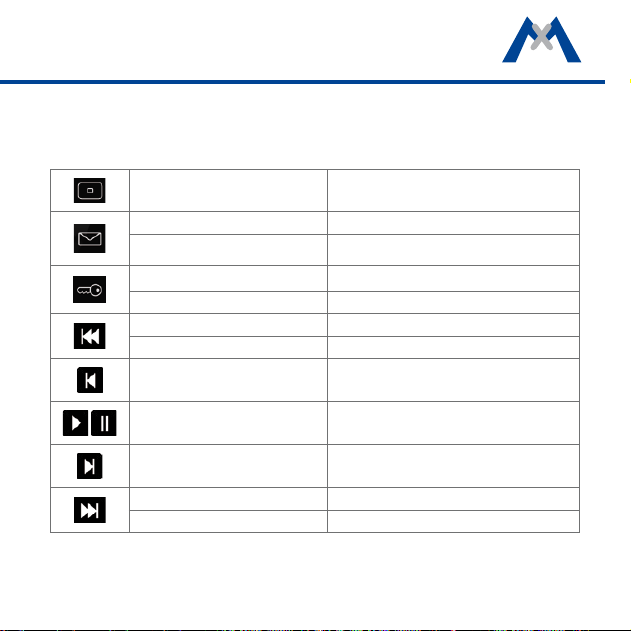
Overview – Shortcuts of the Player
The Player provides shortcuts to dierent functions by tapping or tapping
and holding the dierent buttons and icons.
Tap on Home button Stand-by mode
Tap on Letter button Open event list for this event type
Tap and hold Letter button Open event overview
Tap on Key button Goto Live Image
Tap and hold Key button Open door of connected door station
Tap Jump to previous event
Tap and hold Jump to rst event
Tap One frame backward
Tap Playback | Pause
Tap One frame forward
Tap Jump to next event
Tap and hold Jump to last event

3434

3535
3
System Settings
36
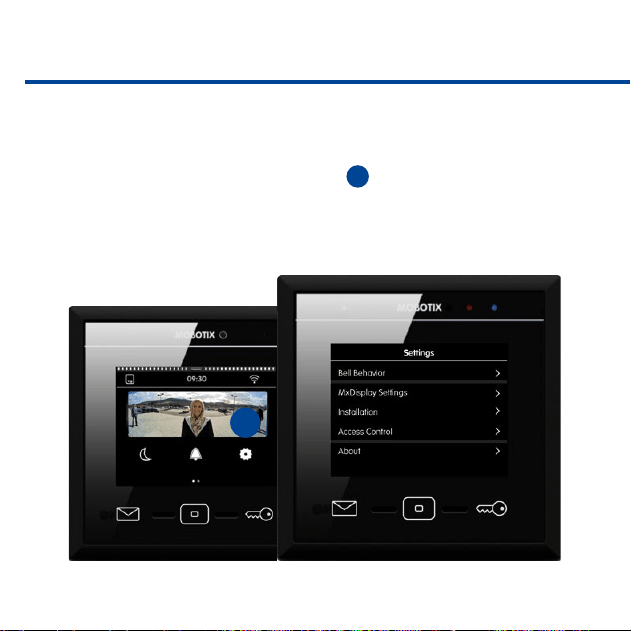
All Settings at One Location
Regardless of whether you want to change the bell behavior, adjust device-spe
-
cic settings, congure the cameras or the system, everything is located in one
menu. To open this menu, tap on Settings
1
in the main menu.
1
37
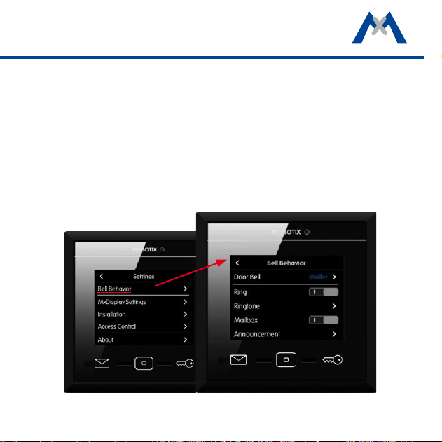
Bell Behavior
When adding a door station, MxDisplay recognizes the door station's bell but-
tons, allowing you to assign the desired doorbells to this MxDisplay.
The Bell Behavior submenu contains the options to set the behavior for each
doorbell button. This includes setting the ring tone and the mailbox announce-
ment. Tap on Setting > Bell Behavior to open the submenu. Select the desired
doorbell in the top right corner and change the settings as required.
38
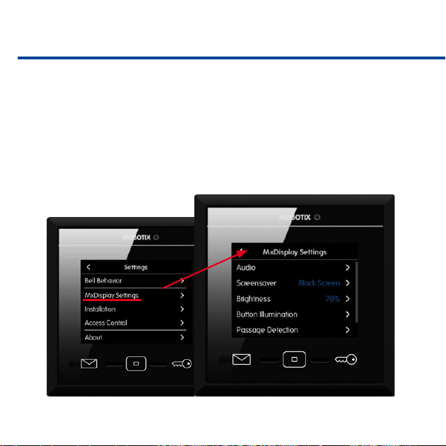
MxDisplay Settings
Use this dialog to change the device-specic settings. This includes the language,
audio settings of the MxDisplay, screen saver and walk-through message. If you
activate the walk-through message in the camera bar (see section Camera Bar),
a sound plays when a door opens that has a door sensor. Allows selecting the
sound and the volume. Tap on Settings > MxDisplay Settings to open the
settings.
39
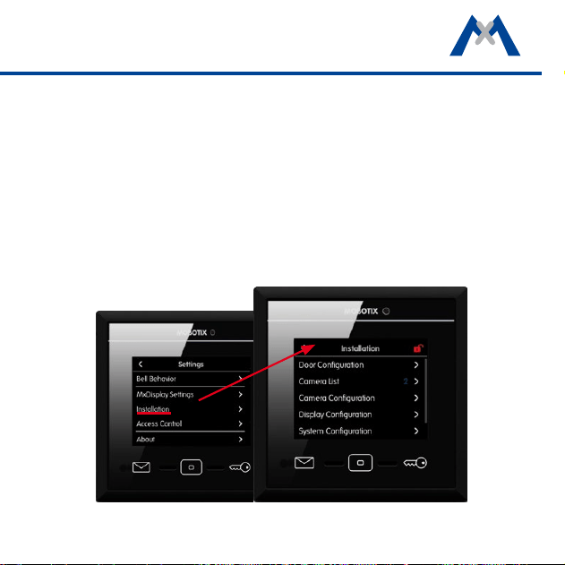
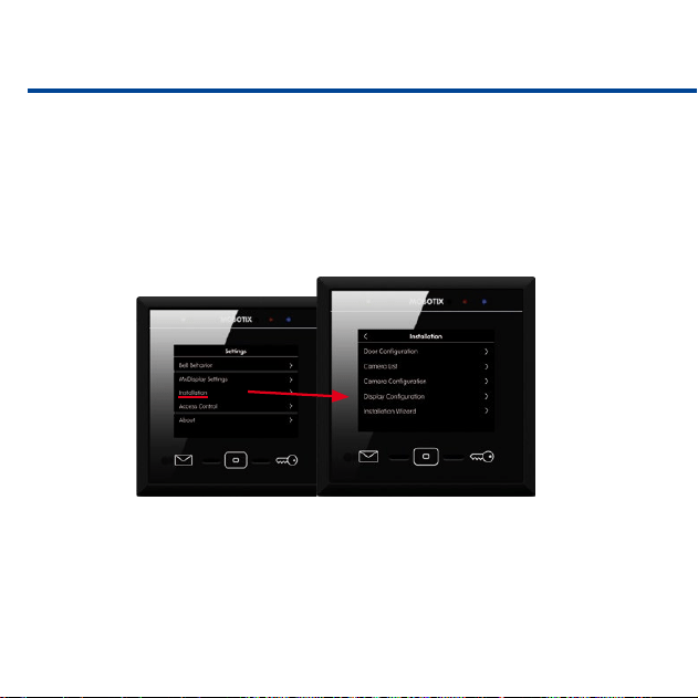
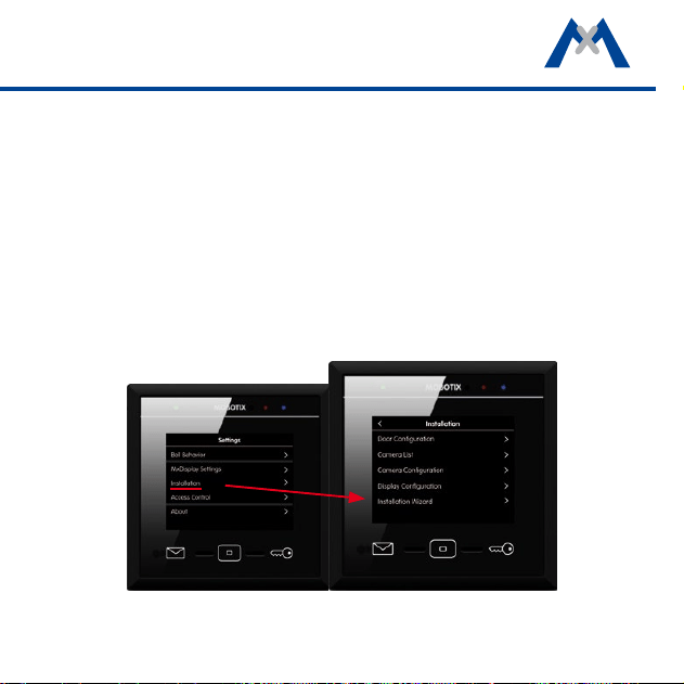
Installation
This menu contains the door conguration that allows creating a bell layout
and provides for setting the bell behavior. It also contains the camera list for
adding and deleting cameras and the camera conguration for setting up record
-
ing.
In addition, the Display Conguration contains the network settings, the time
server and allows managing the settings. The Installation Wizard opens with
the rst start of MxDisplay; however, you can open it any time later from the
Installation menu. Tap on Settings > Installation to open the Installation
menu.
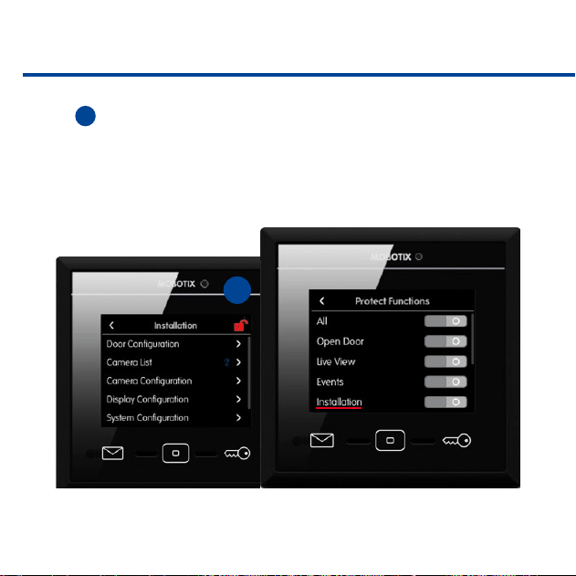
40
It is possible to protect the settings of the Installation menu. Tap on the red
lock
1
and answer "Yes" to close the prompt. The Protect Functions dialog
opens: Activate the Installation option. From now on, you can only change
settings in this menu if you enter the administrator PIN ("0202" by factory default).
1
41
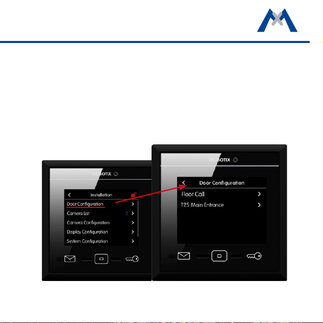
Door Conguration
All door conguration settings can be changed in this menu. Tap on Settings >
Installation > Door Conguration. The view shows the Floor Call option and
all attached door stations.
Note: Since these settings are only needed when conguring for the rst time
and only by the administrator, access to these settings may be locked. In this
case, you will have to enter the administrator PIN (set to "0202" by factory default).
42
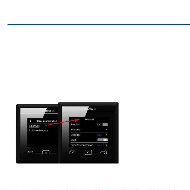
Floor Call
If someone rings the doorbell at the apartment door, you can now use the
MxDisplay to talk to the visitor and to open the door. Before you can do this,
however, the apartment doorbell needs to be connected to the MxDisplay and
the signal inputs and outputs must have been assigned accordingly. To assign
the inputs and outputs, tap on Floor Call.
1. Activate the slider for this option. Select a ring tone that is dierent from
the one at the door station, so you can tell if someone is ringing at the door
station or at the apartment door.
2. Tap on Doorbell and assign the corresponding signal input. To properly
see the door status, assign the corresponding inputs to the door sensor
(door open/closed) and the
door lock sensor (door
locked/unlocked). Tap on
Door Opener and assign
the corresponding signal
output.
43
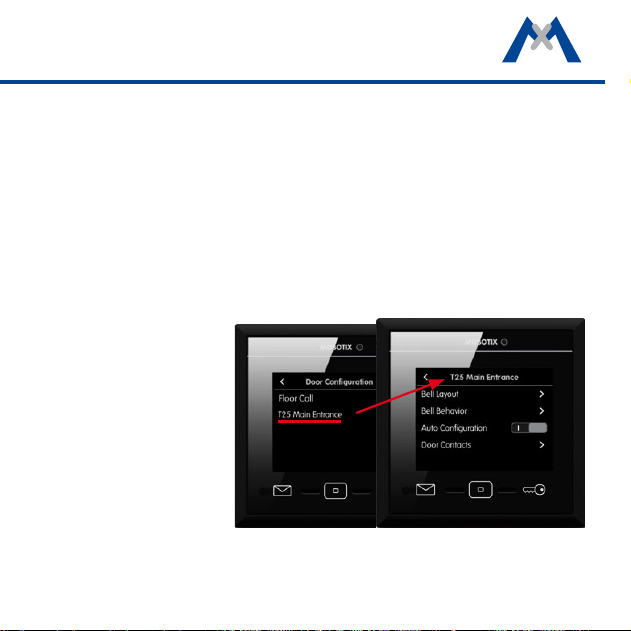
Door Conguration
Open this view to change the door station settings. Select the door station you
want to congure.
• Bell Layout
Allows conguring the access modules of the corresponding door stations.
Tap on Bell Layout. The attached access modules are displayed as graph-
ics, allowing you to change the settings.
• Bell Behavior
Allows setting the desired behavior for each door station and doorbell
(main door).
• Auto Conguration
Allows locking the auto
conguration to avoid
accidental recongu-
ration.
• Door Sensors
Specify the sensors that
are used as door sen-
sors, door lock sensors
and door opener (main
door).
44
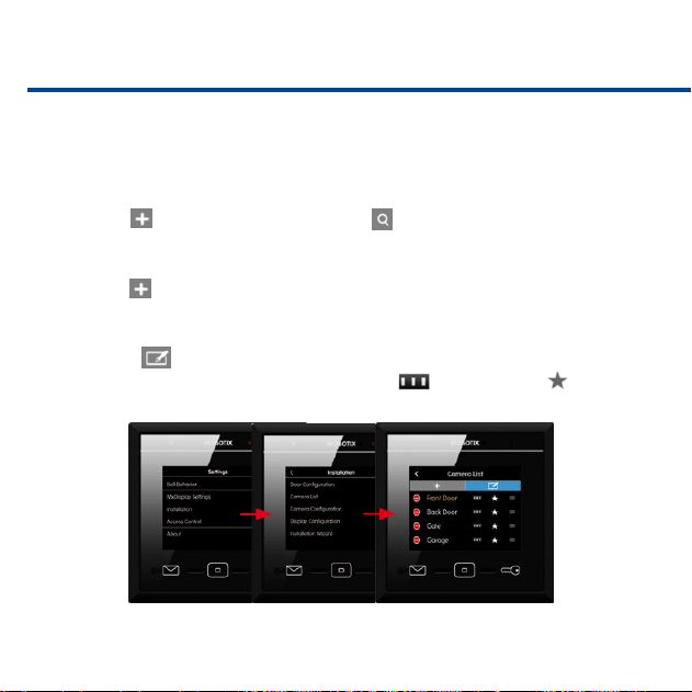
Camera List
Use this list to add cameras and door stations and to edit them later on. Tap
on Settings > Installation > Camera List to open the list.
• Adding Cameras Using Bonjour
Tap on and start the camera search ( ). Select a camera, enter a name,
then enter the camera user name and password.
• Adding Cameras Manually
Tap on and then on Add Manually. Enter the camera name and the URL
(incl. port), then enter the camera user name and password.
• Editing the Camera List
Click on to delete cameras, to change the sorting order and to select
cameras that are shown in the camera bar or as favorites .
45
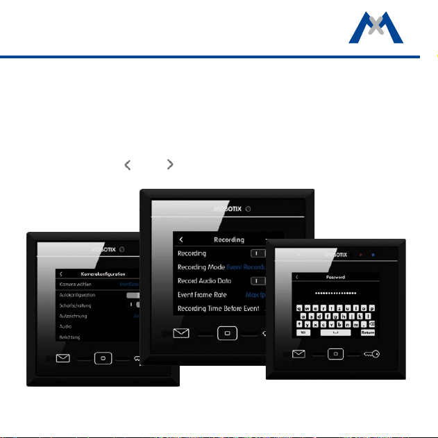
Camera Conguration
The camera conguration is where you congure recording and where you select
the events that will trigger recordings. For door stations, you can lock the auto
conguration to avoid accidental reconguration. If required, you can also change
the admin password for accessing the camera. To open the camera congura-
tion, tap on Settings > Installation > Camera Conguration. Select the desired
camera using the and arrows and change its settings.
46
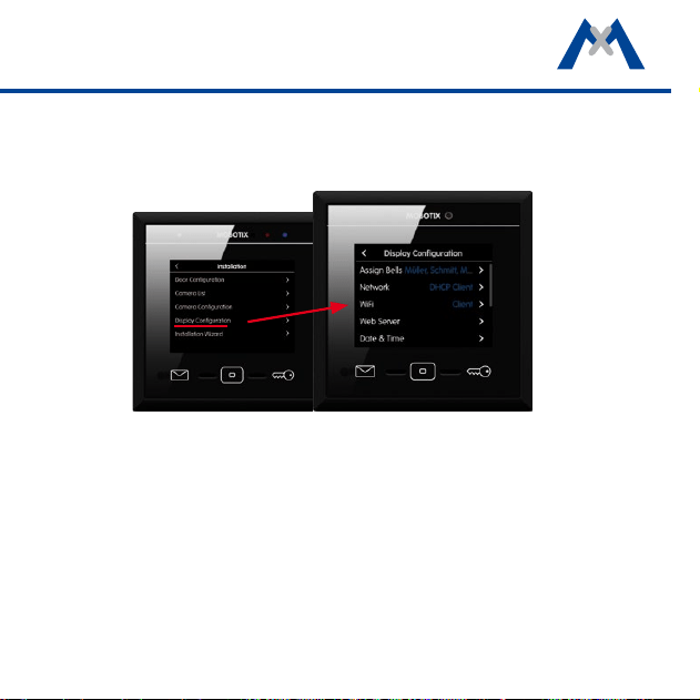
Display Conguration
You can assign the door bells to the MxDisplay, set the LAN network parameters
and activate the WiFi module of the MxDisplay. You can also activate the time
server client, protect specic functions, add a temperature sensor, manage the
settings and change the administrator PIN ("0202" by factory default). To open
the display conguration, tap on Settings > Installation > Display Congu-
ration.
Protect functions: The following functions can be locked: To use a protected
function, users needs to enter their PIN code. To assign the rights for executing
specic functions for users and their PINs, open the Access Control dialog (see
section Access Control).
47
Select the WiFi Mode
Tap on Display Conguration > WiFi > Mode to open the menu. The following
operating modes are available for the MxDisplay:
• Client:
The MxDisplay can connect to a DSL router (or a dierent DHCP server) as
WiFi client and can access the cameras on the local network.
• Extend Network (AP):
The MxDisplay is connected to a DSL router (or a dierent DHCP server)
via LAN and extends the local camera network of the router by serving as
a WiFi access point. Other devices (e.g., smartphones) can use the MxDisplay
as WiFi clients to connect to the local camera network.

48
• Separate Network (AP):
The MxDisplay is connected via LAN to the local camera network (DSL router
or dierent DHCP server). At the same time, the MxDisplay serves as WiFi
access point with its own DHCP server. Mobile devices (e.g., smartphones)
can use the MxDisplay as WiFi clients to connect to the local camera network.
For this purpose, the MxDisplay forwards the connection requests to the
local network.
• Camera Gateway (Client):
The MxDisplay is connected via LAN to the local camera network. The
MxDisplay uses WiFi (as client) to provide the connection to the DSL router.
The router is connected to the Internet, but does not have a direct connected
to the camera network. If the DSL router can be reached via the Internet
from the outside (e.g., aer registering with a DynDNS service), the MxDisplay
will forward these connection requests to the cameras. Note that the DSL
router must have port forwarding enabled and congured accordingly to
forward the requests to the IP addresses of the cameras in the local network.
49
System Conguration
Open this menu to select one of the attached devices as time server (Settings >
Installation > System Conguration).
Starting the Installation Wizard
The Installation Wizard helps you to add and congure door stations and cam-
eras. The wizard opens automatically when starting MxDisplay for the rst time,
but you can also use it later on to add door stations and cameras. To open the
wizard, tap on Settings > Installation > Installation Wizard. Complete all
steps of the wizard.
50
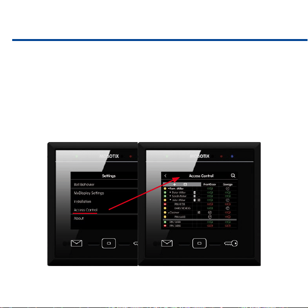
Access Control
This menu allows adding users and assigning RFID cards and PINs to these
users. You can create new tenants, add RFID cards and activate/deactivate RFID
cards. In addition, you can set access times for specic RFID cards. You assign
additional PIN numbers, lock cards and assign rights. For example, you can
specify which card opens which doors and which MxDisplay functions can be
used by the individual users. Tap on Settings > Access Control to open the
menu.
51
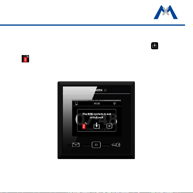
To add a new card, hold the card next to the Home button and follow the instruc-
tions. When training the rst RFID card, you will be asked to initialize the RFID
system. You can initialize the system from a door station. Tap on to do so.
Or you can start the initialization by holding an admin card to the device. Tap
on and follow the instructions.
52
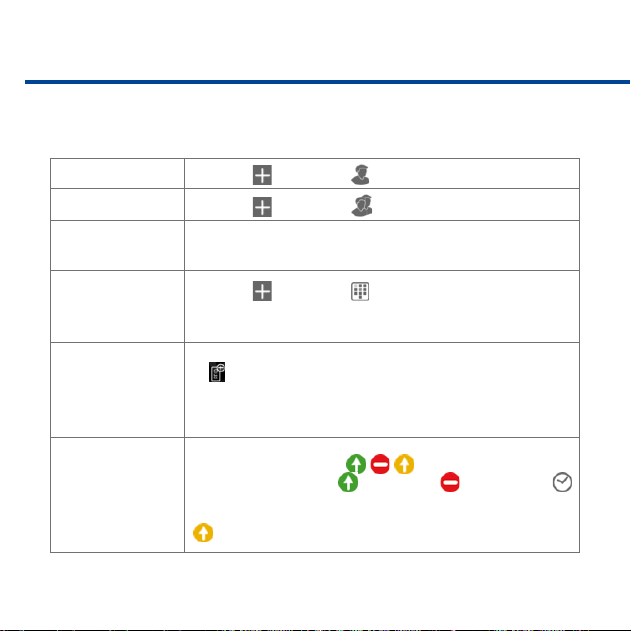
Overview – Shortcuts of the Access Control
The Access Control provides the following functions:
Add Users
1. Tap on and then on .
Add Groups
1. Tap on and then on .
Assign a user to a
group
1. Tap and hold on user name.
2. Tap on Party and then on the group.
Create and assign
PINs
1. Tap on and then on , then enter the PIN.
2. Assign PIN to user: Tap and hold on PIN, click on User, then
select the user.
Train RFID cards and
assign to users
1. Train card: Hold card in front of the MxDisplay, then tap on
. Follow instructions on the MxDisplay.
2. Assign card: Tap and hold on RFID number, click on User,
then select the user.
Set access rights for
all door stations for
groups, users or
PINs/RFID cards
1. Tap on the access icon / / in the rst column.
2. Select type of access:
grant access, deny access or
use access times.
Note: If access times are used, the icon in the first column turns yellow
(
).
53
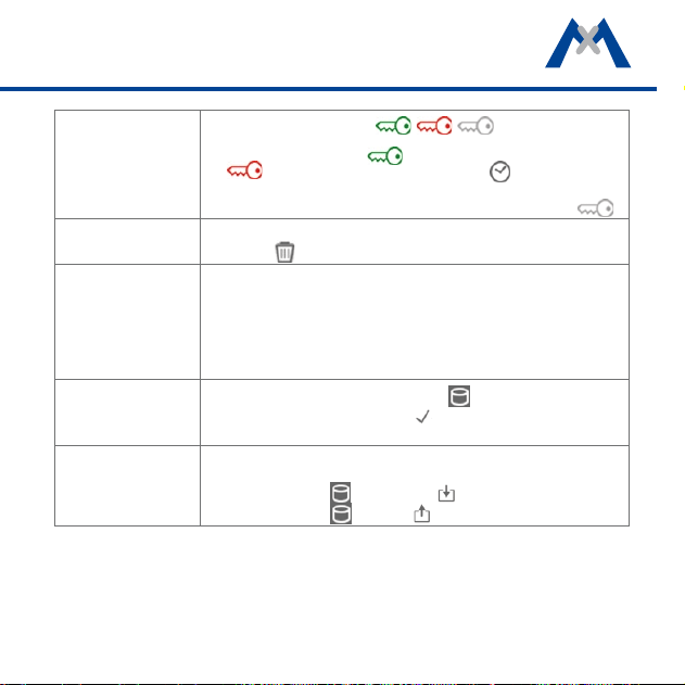
Set access rights for
individual door sta-
tions for groups,
users or PINs/RFID
cards
1. Tap on the access icon / / in the column of
the door station.
2. Select type of access:
grant access for this door station,
deny access to this door station or use access
times.
Note: If access times are used, the icon in the column turns gray ( ).
Delete groups, users,
PINs and RFID cards
1. Tap and hold on the corresponding row.
2. Tap on
.
Set rights for users to
use specific functions
Functions of the MxDisplay can be protected. To use a protected function,
users needs to enter their PIN code (see Protect Functions, section Dis-
play Configuration). To assign the rights for executing specific functions
for users and their PINs, open the Access Control dialog:
1. Tap and hold on user.
2. Tap on Rights and activate the desired rights.
Save settings
If settings have changed in this dialog, the
icon is flashing red.
1. Tap on the icon and then on to save all settings of the
MxDisplay and the door station.
Backup and restore
settings
You can backup all settings to one file and restore the settings from such
a file:
1. Backup: Tap on and then on .
2. Restore: Tap on
, then on and select a le.
54
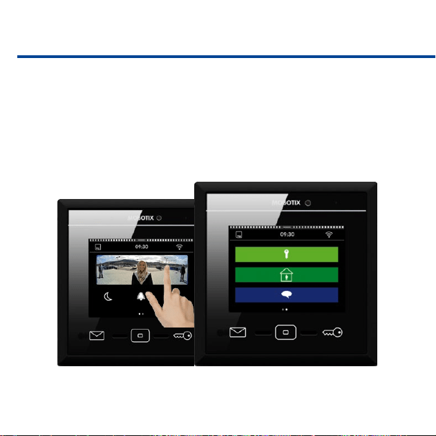
Personalized Interface Settings Fast and Easy
In order to quickly access oen-used functions, you can create customized views.
One view can be used to group up to nine functions with the corresponding
icons and customized colors. To move from the main menu to the view(s), sim-
ply swipe over the view with one nger.
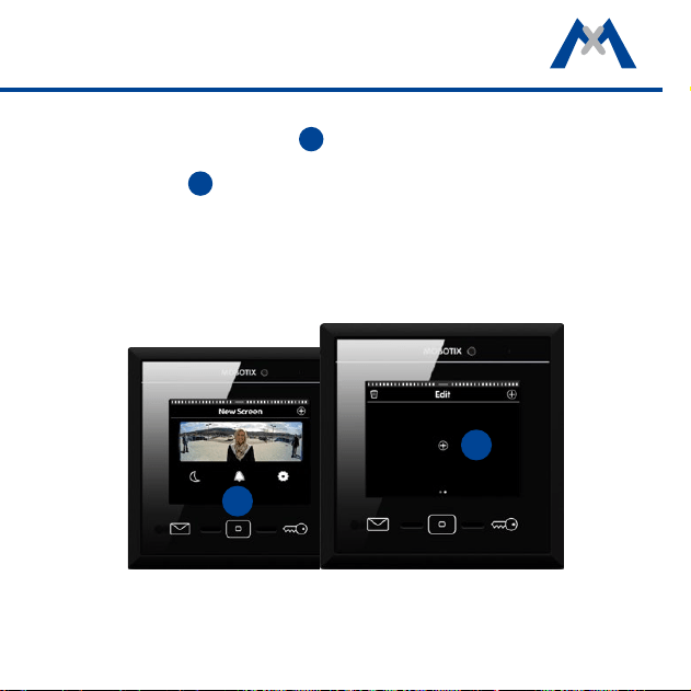
55
To dene a new view, open the main menu (tap on the view in stand-by mode).
Now tap and hold the Home key
1
. The edit mode is now active. Tap on Plus
character in the top right corner. This creates a new view in the main menu.
Then tap on Plus
2
in the center of the view to add function icons and to set
their appearance for this view.
1
2

56

57
Additional Information
For more information on installing and operating MxDisplay, please read the
MxDisplay+ Quick Install, which is available from www.mobotix.com > Sup-
port > Manuals.
Support
Please see www.mobotix.com > Support for information on how to reach
our technical support team.

MOBOTIX AG
Kaiserstrasse
D-67722 Langmeil
Tel.: +49 6302 9816-0
Fax: +49 6302 9816-190
www.mobotix.com
32.526-002_EN_11/2016