www.mobotix.com
Innovations - Made in Germany
The German company MOBOTIX AG is known as the leading pioneer in network camera technology and its decentralized concept has made high-resolution video systems
cost ecient.
MOBOTIX AG • D-67722 Langmeil • Phone: +49 6302 9816-103 • Fax: +49 6302 9816-190 • [email protected]
Security-Vision-Systems
ENEN
Quick Install SurroundMount
Installation
Before installing the sensor modules, make sure that the sensor cables will reach the intended mounting position without placing a strain
on the cables. Separate the sensor modules from the sensor cables before installing the modules. Further information on the individual
camera connectors can be found in Section 2.2.1, “Overview Of Cable Connections” of the S14/S15 camera manuals. Install the base
module as described in Section 2.3.1.
• For surveillance of long and narrow spaces (e.g., bus, train, hallway, etc.)
• Two optical sensor modules are integrated in the mount (S14D or S15D)
• Concealed cabling, weatherproof from -30 to +60 °C (IP65)
• Suitable for ceiling installation, with a 25° tilt of the lenses
Ceiling Mount For Optical
MOBOTIX Sensor Modules
Max. 10cm!
Ceiling
Seal
Seal
Ceiling
Backing plate
MX-OPT-SM-PW
31.823_EN_V4_12/2014
1. Prepare opening
Prepare an opening at the desired mounting position of the SurroundMount
that is large enough (diameter about 30 to 40mm) to allow the sensor cables
to pass through so that you can connect them.
2. Lead the sensor cables through the opening
Lead the sensor cables through the opening in the ceiling and allow them to
protrude through (the longer they extend, the easier the installation).
3. Attach the hinged ferrites
Attach one hinged ferrite to each sensor cable (maximal distance to the
connector 10cm).
4. Select mounting type
Select the appropriate mounting type. Depending on the material and the
thickness of the mounting surface, you can mount the SurroundMount
• directly to the ceiling using the four stainless steel wood screws (item
1.6) with or without the dowels (item 1.7).
• to the ceiling (max. thickness 12 mm) using the backing plate (item 1.2)
and the four stainless steel Allen screws (item 1.8). To do this, you have
to push the screws through the ceiling and tighten them to the backing
plate positioned to the back of the ceiling.
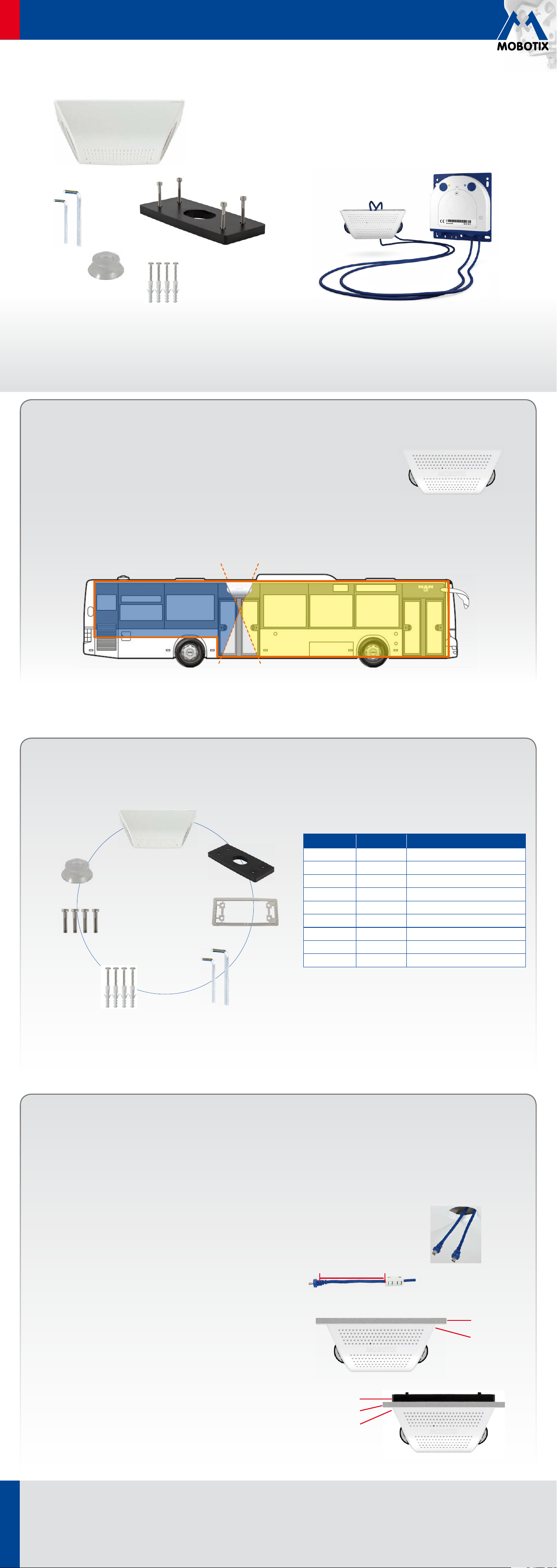
Delivered Parts
For the S14D/S15D FlexMount cameras, two sensor modules with integrated lens, image sensor, LEDs and microphone are connected
(via connector plugs) to the camera housing, which is installed hidden behind a wall or ceiling panel.
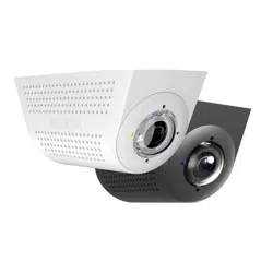
Installing two sensor modules that are pointing in opposite directions in long and narrow spaces (e.g.,
buses, air planes or trains) delivers double hemispheric images of up to 6 megapixels that, in terms
of sharpness of detail, significantly outperforms a single hemispheric camera with just one lens. For
these kinds of installations, MOBOTIX oers the SurroundMount. The 25° tilt of the two sensor modules
on the SurroundMount allows the area directly underneath them to be captured without blind spots.
The SurroundMount can only be used with the following sensor modules of the S14D and S15D (day or night):
L11/L12, L22/L25 and L43/L51.
Item Number Part Name
1.1 1 Housing
1.2 1 Backing plate
1.3 1 Seal
1.4 1 Allen wrench 1.5mm
1.5 1 Allen wrench 3mm
1.6 4 Stainless steel wood screws 4x40
1.7 4 Dowels 6mm
1.8 4 Stainless steel Allen screws M4x30
1.9 1 Removal tool
1.1
1.2
1.3
1.4
1.5
1.6
1.7
1.8
1.9
www.mobotix.com
Innovations - Made in Germany
The German company MOBOTIX AG is known as the leading pioneer in network camera technology and its decentralized concept has made high-resolution video systems
cost ecient.
MOBOTIX AG • D-67722 Langmeil • Phone: +49 6302 9816-103 • Fax: +49 6302 9816-190 • [email protected]
Security-Vision-Systems
ENEN
Quick Install SurroundMount
Drilling Template
150 mm
108 mm
Copyright © MOBOTIX AG 2014 • Made in Germany • Technical information subject to change without notice.
65 mm
30 mm
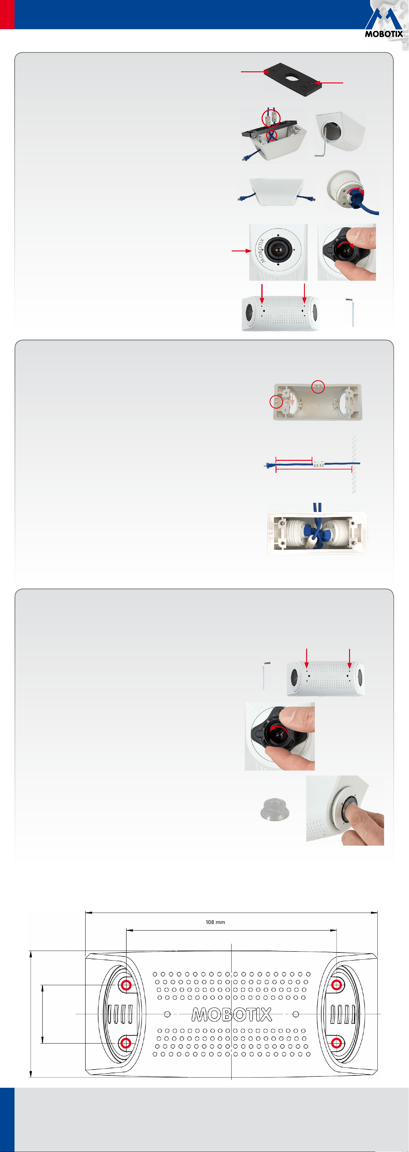
Replacing Sensor Modules
The following optical sensor modules can be mounted in the SurroundMount housing:
• S14D: L11, L22, L43 (Day and Night each)
• S15D: L12, L25, L51 (Day and Night each)
To replace the sensor modules you need the removal tool, which is included with the delivered parts.
1. Loosen set screws
Loosen the four set screws on the underside of the housing using the 1.5mm
Allen wrench.
2. Loosen sensor module
Turn the sensor module with the black module wrench (provided with the
S15D) to the left until it reaches the stop (MOBOTIX lettering in the “9-o’clock
position”). Remove the black module wrench.
3. Remove sensor module
Place the removal tool (provided in the package) onto the sensor module.
Remove the module and disconnect it from the sensor cable.
4. Replacing sensor module
After disconnecting the sensor module from the sensor cable, proceed as
described in Installation (7. Connect sensor cables, 8. Attach sensor modules
and 9. Secure sensor modules).
M
O
B
O
T
I
X
M
O
B
O
T
I
X
5. Set dowels or prepare screw holes
Depending on the desired mounting type, you either set the dowels or prepare
screw holes (for the backing plate). In the second case, you can either use
the drilling template provided at the end of this document or use the backing
plate with its four threaded bushings as a drilling template.
6. Mount the housing
Place the seal (item 1.3) on the SurroundMount housing (item 1.1). Attach the
housing with or without dowels (item 1.7) to the ceiling using the stainless
steel wood screws (item 1.6). When using the backing plate (behind ceiling
boards or roof linings) use the stainless steel Allen screws (item 1.8). You will
need a crosstip screwdriver for the wood screws; for the Allen screws you
will need the 3 mm Allen wrench provided in the package. Because space
is limited in the housing, cross the sensor cables and leave the hinged
ferrites outside the housing.
7. Connect sensor cables
Connect a sensor cable to each sensor module (one cable through each
opening of the housing). Insert the sensor cable in the socket of the module,
attach the bayonet catch and turn it to the right until it clicks into place.
8. Attach sensor modules
Make sure that the MOBOTIX lettering on the front of the sensor module is
pointing to the “9-o’clock position” as shown in the figure. Turn the sensor
module with the black module wrench (provided with the S15D) to the right
until it reaches the stop.
9. Secure sensor modules
Tighten the four set screws on the underside of the housing to secure each
of the sensor modules. To do this, use the provided 1.5mm Allen wrench.
Warning: Do not overtighten the screws (plastic housing!).
Additional Mounting Option
Surface mounting of the sensor cables
Instead of concealed cable routing, the two sensor cables can also be laid openly to the
SurroundMount (both either on the long side or on the short side of the housing). For that
you need to pry open two of the four cable openings (see right image) on the wall of the
housing (this can be done, e.g., with small pliers). Recommended mounting steps for a
cable routing on the long side of the housing:
1. Prepare screw holes (see drilling template on the backside)
When selecting the mounting positions for the SurroundMount and the camera housing,
ensure that the sensor cables are long enough so that they can be stored easily together
with the hinged ferrites in the SurroundMount housing. For that we recommend to maintain
a distance of 12cm between the opening of the housing and the bend relief of the plug.
2. Lead the sensor cables into the housing and attach the hinged ferrites
Attach one hinged ferrite to each sensor cable. We recommend to maintain a distance
of 6cm between the ferrite and the bend relief of the plug.
3. Attach housing
Insert the sensor cables into the mount and place the seal (item 1.3) on the housing. Make
sure that the notches of the seal are positioned over the used cable openings. Attach the
housing to the ceiling.
4. Connect sensor cables, attach sensor modules and secure them
Follow the steps 7 to 9 described in section „Installation“. When inserting the sensor
modules make sure that you push the sensor cables with the ferrites to the right and left
to have enough space for the plugs with the bayonet catches (see right image).
6cm
12cm
Housing
opening
Scale 1:1