

Legal Informaon
User Manual
©2019 Hangzhou Hikvision Digital Technology Co., Ltd.
About this Manual
This Manual is subject to domesc and internaonal copyright protecon.
Hangzhou Hikvision Digital Technology Co., Ltd. ("Hikvision") reserves all
rights to this manual. This manual cannot be reproduced, changed,
translated, or distributed, parally or wholly, by any means, without the
prior wrien permission of Hikvision.
Please use this user manual under the guidance of professionals.
Trademarks
and other Hikvision marks are the property of
Hikvision and are registered trademarks or the subject of applicaons for
the same by Hikvision and/or its aliates. Other trademarks menoned in
this manual are the properes of their respecve owners. No right of license
is given to use such trademarks without express permission.
Disclaimer
TO THE MAXIMUM EXTENT PERMITTED BY APPLICABLE LAW, HIKVISION
MAKES NO WARRANTIES, EXPRESS OR IMPLIED, INCLUDING WITHOUT
LIMITATION THE IMPLIED WARRANTIES OF MERCHANTABILITY AND FITNESS
FOR A PARTICULAR PURPOSE, REGARDING THIS MANUAL. HIKVISION DOES
NOT WARRANT, GUARANTEE, OR MAKE ANY REPRESENTATIONS REGARDING
THE USE OF THE MANUAL, OR THE CORRECTNESS, ACCURACY, OR
RELIABILITY OF INFORMATION CONTAINED HEREIN. YOUR USE OF THIS
MANUAL AND ANY RELIANCE ON THIS MANUAL SHALL BE WHOLLY AT YOUR
OWN RISK AND RESPONSIBILITY.
REGARDING TO THE PRODUCT WITH INTERNET ACCESS, THE USE OF
PRODUCT SHALL BE WHOLLY AT YOUR OWN RISKS. HIKVISION SHALL NOT
Network Indoor
Staon Operaon Guide
i

TAKE ANY RESPONSIBILITIES FOR ABNORMAL OPERATION, PRIVACY
LEAKAGE OR OTHER DAMAGES RESULTING FROM CYBER ATTACK, HACKER
ATTACK, VIRUS INSPECTION, OR OTHER INTERNET SECURITY RISKS;
HOWEVER, HIKVISION WILL PROVIDE TIMELY TECHNICAL SUPPORT IF
REQUIRED.
SURVEILLANCE LAWS VARY BY JURISDICTION. PLEASE CHECK ALL RELEVANT
LAWS IN YOUR JURISDICTION BEFORE USING THIS PRODUCT IN ORDER TO
ENSURE THAT YOUR USE CONFORMS THE APPLICABLE LAW. HIKVISION
SHALL NOT BE LIABLE IN THE EVENT THAT THIS PRODUCT IS USED WITH
ILLEGITIMATE PURPOSES.
IN THE EVENT OF ANY CONFLICTS BETWEEN THIS MANUAL AND THE
APPLICABLE LAW, THE LATER PREVAILS.
Network Indoor
Staon Operaon Guide
ii
Symbol Convenons
The symbols that may be found in this document are dened as follows.
Symbol Descripon
Danger
Indicates a hazardous situaon which, if not avoided, will or
could result in death or serious injury.
Cauon
Indicates a potenally hazardous situaon which, if not
avoided, could result in equipment damage, data loss,
performance degradaon, or unexpected results.
Note
Provides addional informaon to emphasize or
supplement important points of the main text.
Network Indoor Staon Operaon Guide
iii
Safety Instrucon
Warning
•
The working temperature of the device is from -10 ºC to 55 ºC.
•
All the electronic operaon should be strictly compliance with the electrical
safety regulaons, re prevenon regulaons and other related regulaons in
your local region.
•
Please use the power adapter, which is provided by normal company. The power
consumpon cannot be less than the required value.
•
Do not connect several devices to one power adapter as adapter overload may
cause over-heat or re hazard.
•
Please make sure that the power has been disconnected before you wire, install
or dismantle the device.
•
When the product is installed on wall or ceiling, the device shall be rmly xed.
•
If smoke, odors or noise rise from the device, turn
o the power at once and
unplug the power cable, and then please contact the service center.
•
If the product does not work properly, please contact your dealer or the nearest
service center. Never aempt to disassemble the device yourself. (We shall not
assume any responsibility for problems caused by unauthorized repair or
maintenance.)
Cauon
•
Do not drop the device or subject it to physical shock, and do not expose it to
high electromagnesm radiaon. Avoid the equipment installaon on vibraons
surface or places subject to shock (ignorance can cause equipment damage).
•
Do not place the device in extremely hot (refer to the specicaon of the device
for the detailed
operang temperature), cold, dusty or damp locaons, and do
not expose it to high electromagnec radiaon.
•
The device cover for indoor use shall be kept from rain and moisture.
•
Exposing the equipment to direct sun light, low
venlaon or heat source such
as heater or radiator is forbidden (ignorance can cause
re danger).
•
Do not aim the device at the sun or extra bright places. A blooming or smear
may occur otherwise (which is not a
malfuncon however), and aecng the
endurance of sensor at the same me.
Network Indoor
Staon Operaon Guide
iv
•
Please use the provided glove when open up the device cover, avoid direct
contact with the device cover, because the acidic sweat of the ngers may erode
the surface coang of the device cover.
•
Please use a so and dry cloth when clean inside and outside surfaces of the
device cover, do not use alkaline detergents.
•
Please keep all wrappers aer unpack them for future use. In case of any failure
occurred, you need to return the device to the factory with the original wrapper.
Transportaon without the original wrapper may result in damage on the device
and lead to addional costs.
•
Improper use or replacement of the baery may result in hazard of explosion.
Replace with the same or equivalent type only. Dispose of used baeries
according to the instrucons provided by the baery manufacturer.
•
Input voltage should meet both the SELV and the Limited Power Source
according to 60950-1 standard.
•
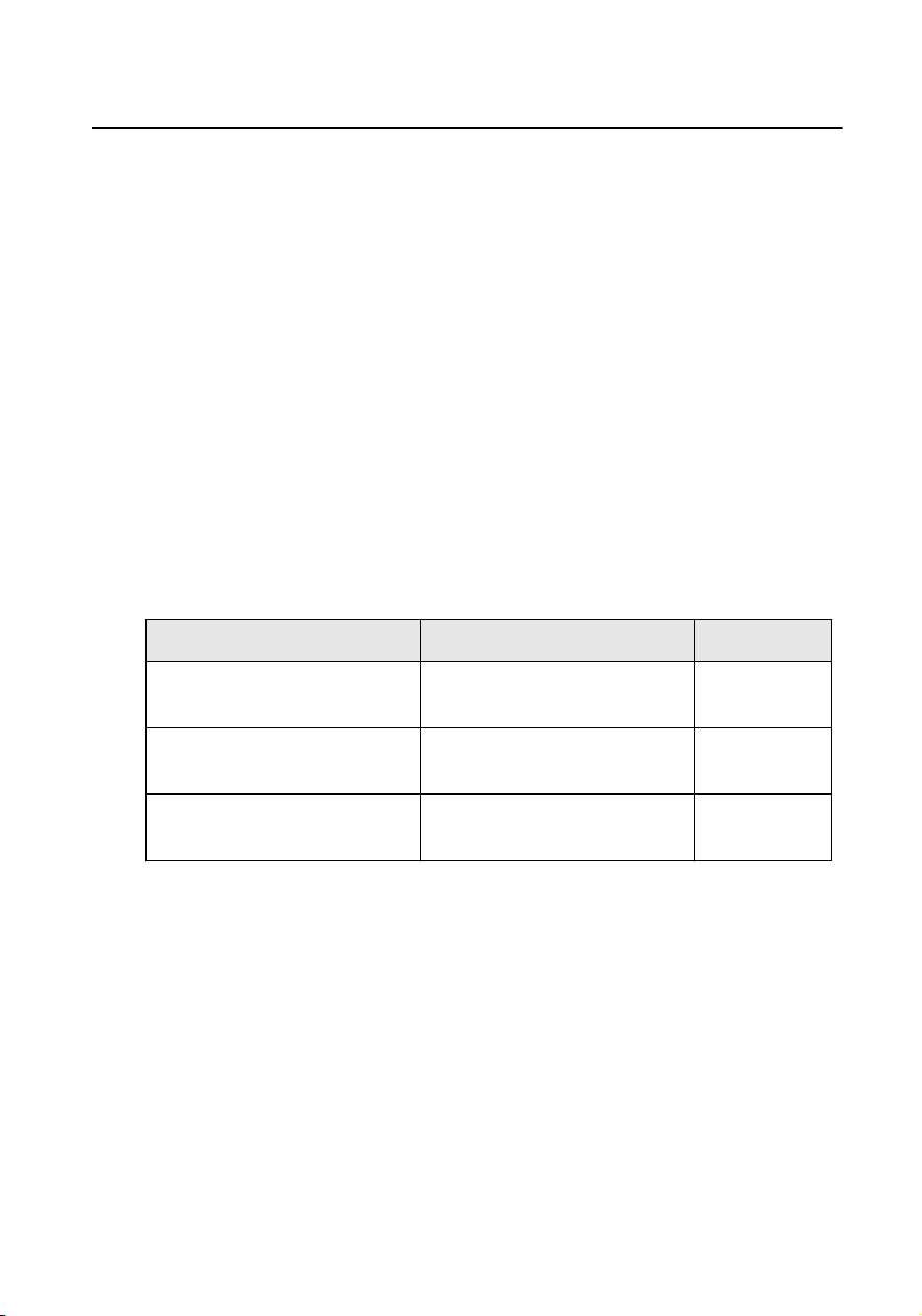
The power supply must conform to LPS. The recommended adaptor models and
manufacturers are shown as below. Use the
aached adapter, and do not
change the adaptor randomly.
Model Manufacturer Standard
ADS-24S-12 1224GPCN SHENZHEN HONOR
ELECTRONIC CO.,LTD
CEE
G0549-240-050 SHENZHEN GOSPELL DIGITAL
TECHNOLOGY CO.,LTD
CEE
TS-A018-120015Ec SHENZHEN TRANSIN
TECHNOLOGIES CO., LTD
CEE
Network Indoor Staon Operaon Guide
v

Contents
1 Local Operaon .......................................................................................... 1
1.1 Call Sengs ....................................................................................................... 1
1.1.1 Add Contact .............................................................................................. 1
1.1.2 Call Resident ............................................................................................. 1
1.1.3 Call Indoor Extension/Indoor Staon ....................................................... 2
1.1.4 Receive Call ............................................................................................... 2
1.1.5 View Call Logs ........................................................................................... 3
1.2 Live View ........................................................................................................... 3
1.3 Arm/Disarm ....................................................................................................... 4
1.3.1 Arm Room ................................................................................................. 5
1.3.2 Disarm Room ............................................................................................ 5
1.4 Arming Mode
Sengs ....................................................................................... 6
1.5 Informaon Management ................................................................................. 7
2 Remote Operaon via the client soware ................................................. 9
2.1 Call Indoor
Staon ............................................................................................. 9
2.2 Receive Call from Indoor Staon/Door Staon ............................................... 10
2.3 View Live Video of Door Staon and Outer Door Staon ............................... 11
2.4 View Call Logs ................................................................................................. 12
2.5 Release Noce ................................................................................................ 12
2.6 Search Video Intercom Informaon ................................................................ 14
2.6.1 Search Call Logs ...................................................................................... 14
2.6.2 Search Unlocking Logs ............................................................................ 15
Network Indoor
Staon Operaon Guide
vi

1 Local Operaon
1.1 Call Sengs
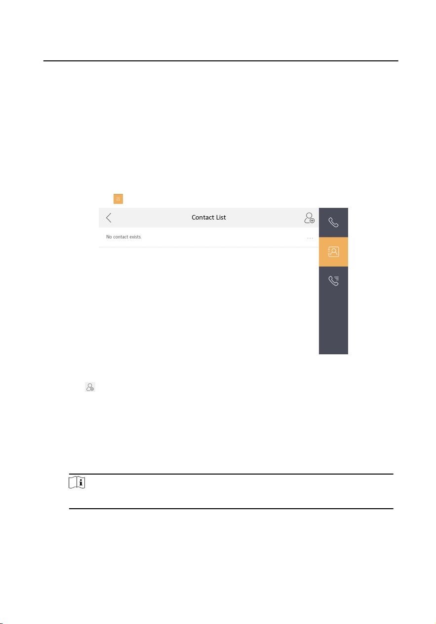
1.1.1 Add Contact
Steps
1.
Tap Call →
to enter the contact list page.
Figure 1-1 Contact List
2.
Tap to pop up the contact adding dialog.
3.
Enter contact informaon.
•
If you adopt private SIP protocol, enter the contact name and the room No.
•
If you adopt standard SIP protocol, enter the contact name and the phone
number of VOIP account.
4.
Tap OK to save the
sengs.
Note
Up to 200 contacts can be added.
1.1.2 Call Resident
Network Indoor Staon Operaon Guide
1
Steps
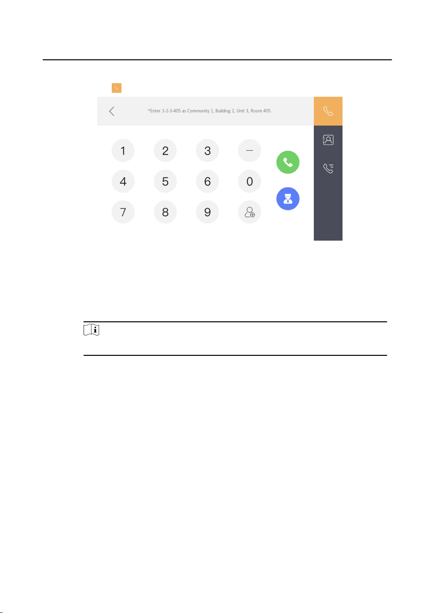
1.
Tap Call → to enter the residents calling page.
Figure 1-2 Call Resident
2.
Enter the calling number.
•
When you adopt private SIP protocol, the calling number format should be x-
x-x-xxx. For example, the calling number of Community 1, Building 2, Unit 3,
and Room 405 is 1-2-3-405.
Note
The community No. can be omied.
•
When you adopt standard SIP protocol, the calling number should be the
phone number of VOIP account.
3.
Tap the call buon to start an audiovisual call.
1.1.3 Call Indoor Extension/Indoor
Staon
If you install indoor staon and indoor extensions at home, you can call the indoor
extension via your indoor
staon, and vice versa.
Enter 【0-indoor extension No.】 on the indoor
staon to start calling.
Enter 【0-0】 to call the indoor staon from the indoor extension.
1.1.4 Receive Call
The indoor staon and indoor extension can receive calls from the door staon, the
master staon or iVMS-4200 Client.
Network Indoor
Staon Operaon Guide
2
On the call from door staon interface, there are 2 unlock buons: Unlock 1, and
Unlock 2. When you tap Unlock 1, the building gate will open by default, and when
you tap Unlock 2, the door connected to the door staon with the secure control
door unit will open.
Tap the capture buon to capture the live view picture when speaking with the door
staon. And prompts "Captured" will display on the screen.
Indoor extension can receive calls from the door staon and the master staon only.
1.1.5 View Call Logs
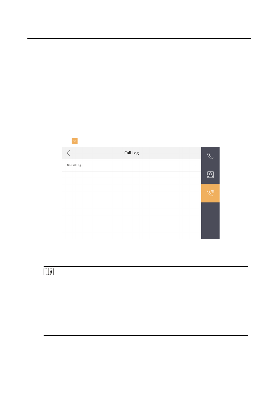
Steps
1.
Tap Call →
to enter the call log page.
Figure 1-3 Call Logs
2.
Tap a piece of call logs in the list to call back.
Note
•
Indoor extension does not support this funcon.
•
The indoor staon saves call logs from door staon, outer door staon,
management center and other indoor staons.
•
Hold a piece of call logs to open the call logs handling menu.
•
Tap Delete to delete the piece of call logs.
•
Tap Clear to delete all pieces of call logs.
1.2 Live View
Network Indoor Staon Operaon Guide
3
On the live view page, you can view the live video of added door staon and
network camera.
Steps
Note
•
Make sure the network camera or door staon is well-connected.
•
Make sure the indoor extension and the indoor staon are well-connected.
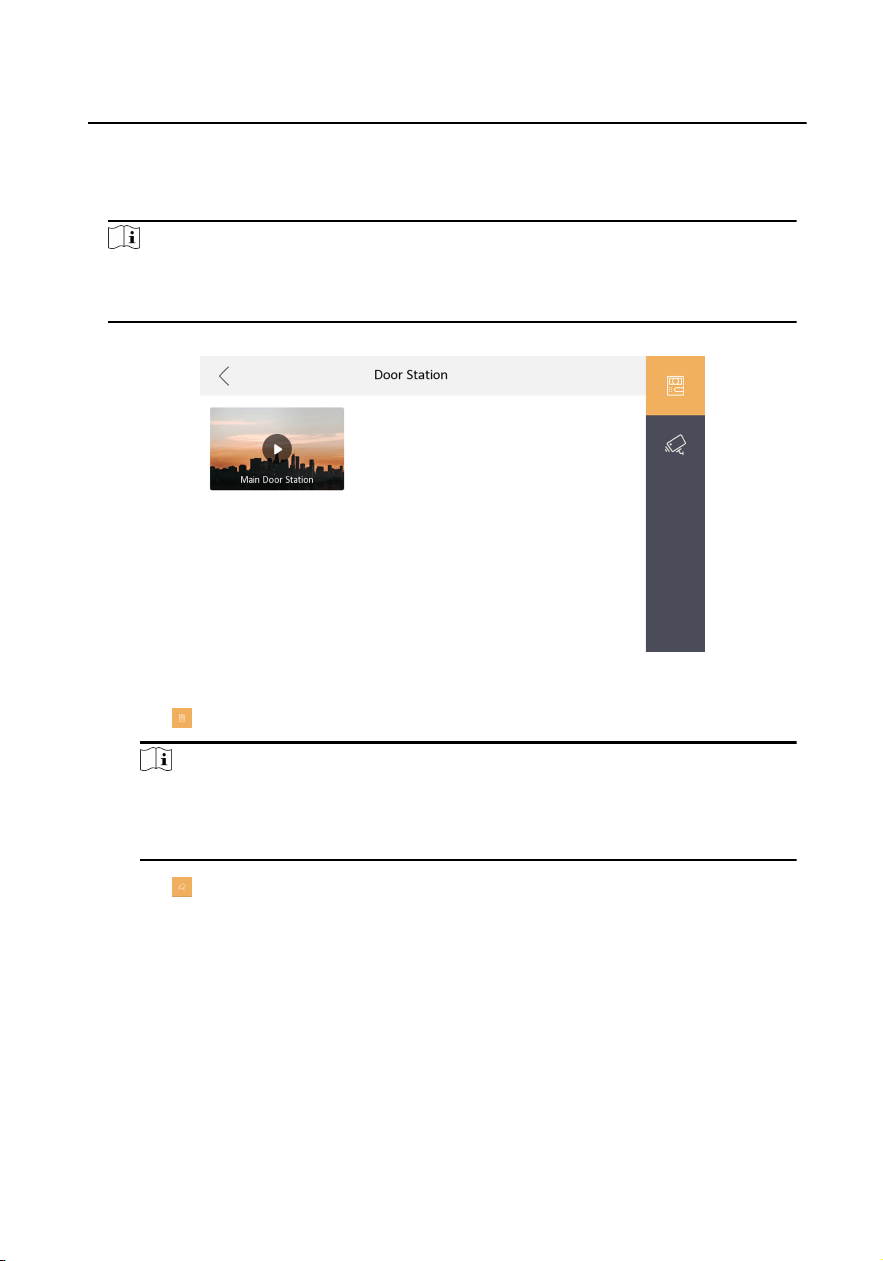
1.
Tap Live View to enter the live view page.
Figure 1-4 Live View
2.
Tap to enter the live view page of door staon.
Note
On the Call from Door Staon page, there are 2 unlock buons: Unlock 1, and
Unlock 2. When you tap Unlock 1, the building gate will open by default. When
you tap Unlock 2, the door staon connected door will open.
3.
Tap to enter the live view page of network cameras.
1.3 Arm/Disarm
The indoor staon has four kinds of scene modes: sleeping mode, stay mode, away
mode, and custom mode. You can arm or disarm your room in each scene mode
manually. The selected scene mode will be displayed on the main page of the indoor
staon.
Network Indoor
Staon Operaon Guide
4
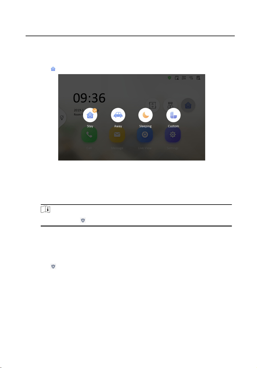
1.3.1 Arm Room
Steps
1.
Tap to enter the scene page.
Figure 1-5 Arm Sengs page
2.
Select Stay, Away, Sleeping or Custom.
3.
Enter the scene password to enable the scene.
4.
Tap OK.
Note
You can also tap → One-Push to Arm to enable the scene.
1.3.2 Disarm Room
Steps
1.
Tap
→ One-Push to Disarm to disarm.
Network Indoor
Staon Operaon Guide
5
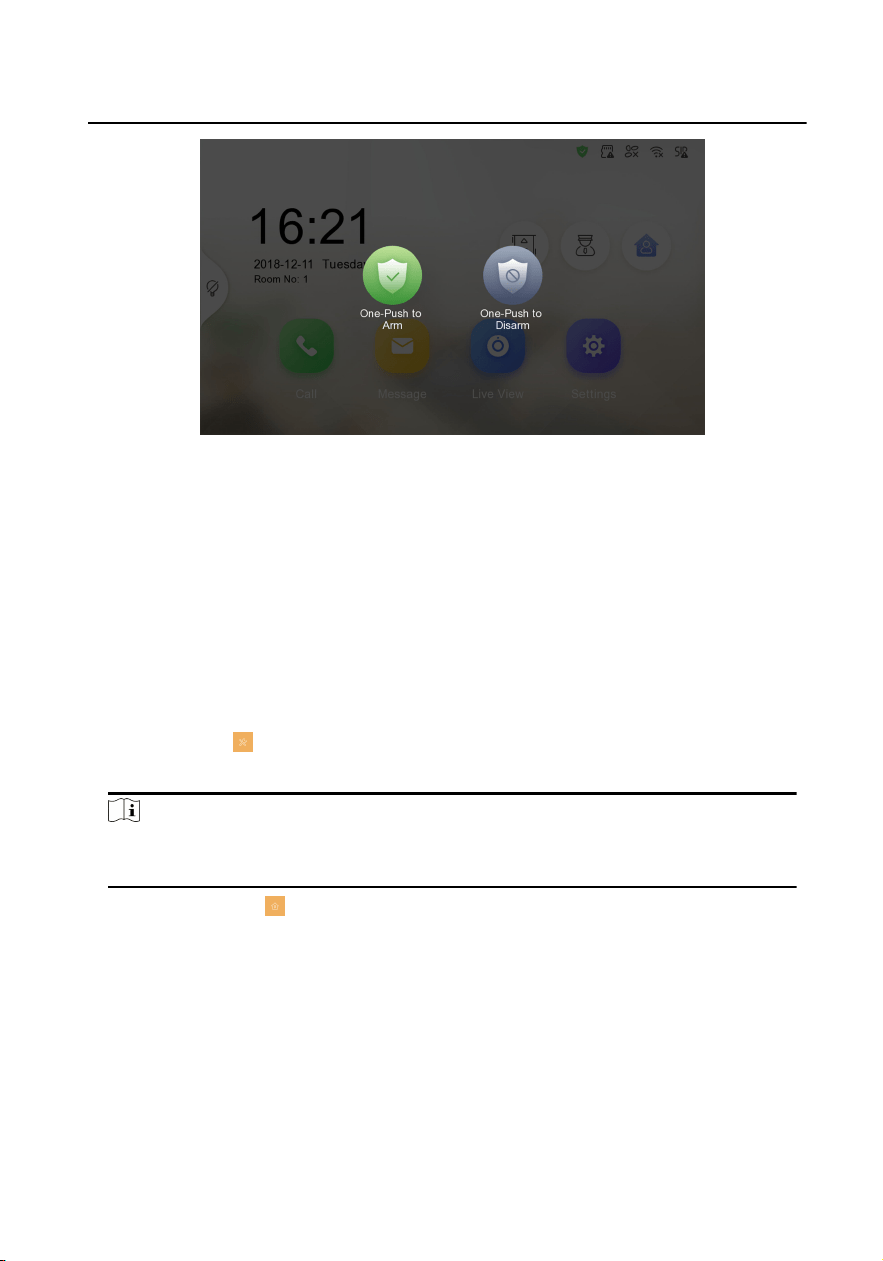
Figure 1-6 Disarm Room
2.
Enter the scene password.
3.
Tap OK.
1.4 Arming Mode
Sengs
4 arming modes can be congured: stay mode, away mode, sleeping mode and
custom mode.
Before You Start
Tap Sengs → → Preference to enable Alarm.
Steps
Note
Arming status page and zone sengs page are hidden by default. You should enable
alarm funcon rst.
1.
Tap Sengs → to enter the arming mode sengs page.
2.
Tap Stay Mode, Away Mode, Sleeping Mode, or Custom to enter the page.
Network Indoor
Staon Operaon Guide
6
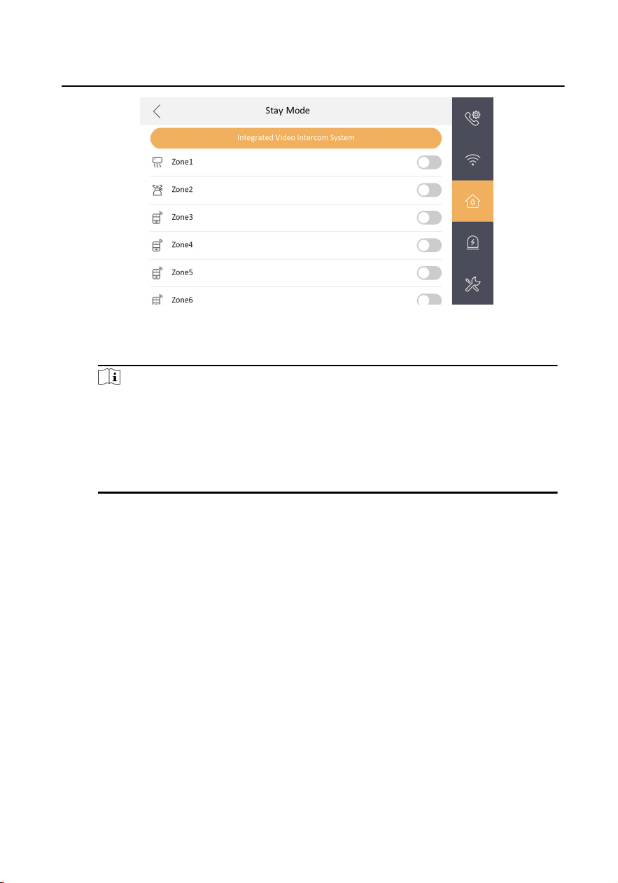
Figure 1-7 Arming Mode Sengs
3.
Arm the selected zone.
Note
•
Zones are congurable on the arming mode page.
•
24H alarm zone including smoke detector zone and gas detector zone will be
triggered even if they are disabled.
•
Arming mode
sengs should be congured with the sengs of arming
status on the user page of the device.
1.5 Informaon Management
You can view public noce, visitor message, alarm log and capture log on
informaon management page.
Tap Message to enter the
informaon management page. (Here takes the alarm log
page as an example.)
Network Indoor
Staon Operaon Guide
7
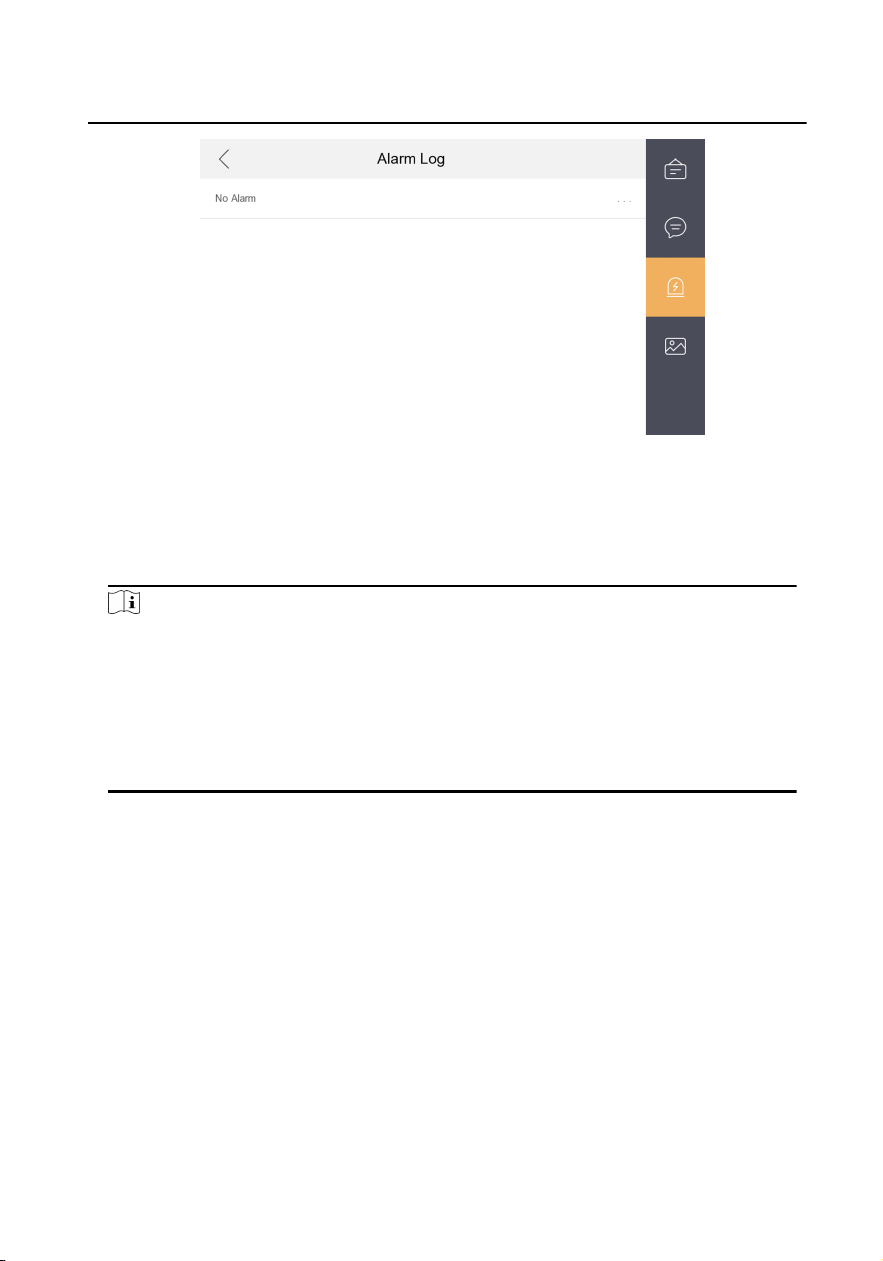
Figure 1-8 Alarm Logs
Delete a Log: Hold the item, you can delete it.
Clear Logs: Hold the item, you can clear all logs.
See Details: Hold a alarm log, you can see the alarm details.
Note
•
Indoor extension only supports alarm log and capture log.
•
It requires TF card for saving the noce, visitor messages and capture logs of the
indoor staons, and requires the internal memory of the indoor staon to save
the alarm log.
•
Up to 200 noces, 200 visitor messages, 200 alarm logs, and 200 capture logs
can be saved.
Network Indoor Staon Operaon Guide
8
2 Remote Operaon via the client
soware
The Video Intercom module provides remote control and conguraon on video
intercom products via the iVMS-4200 client
soware.
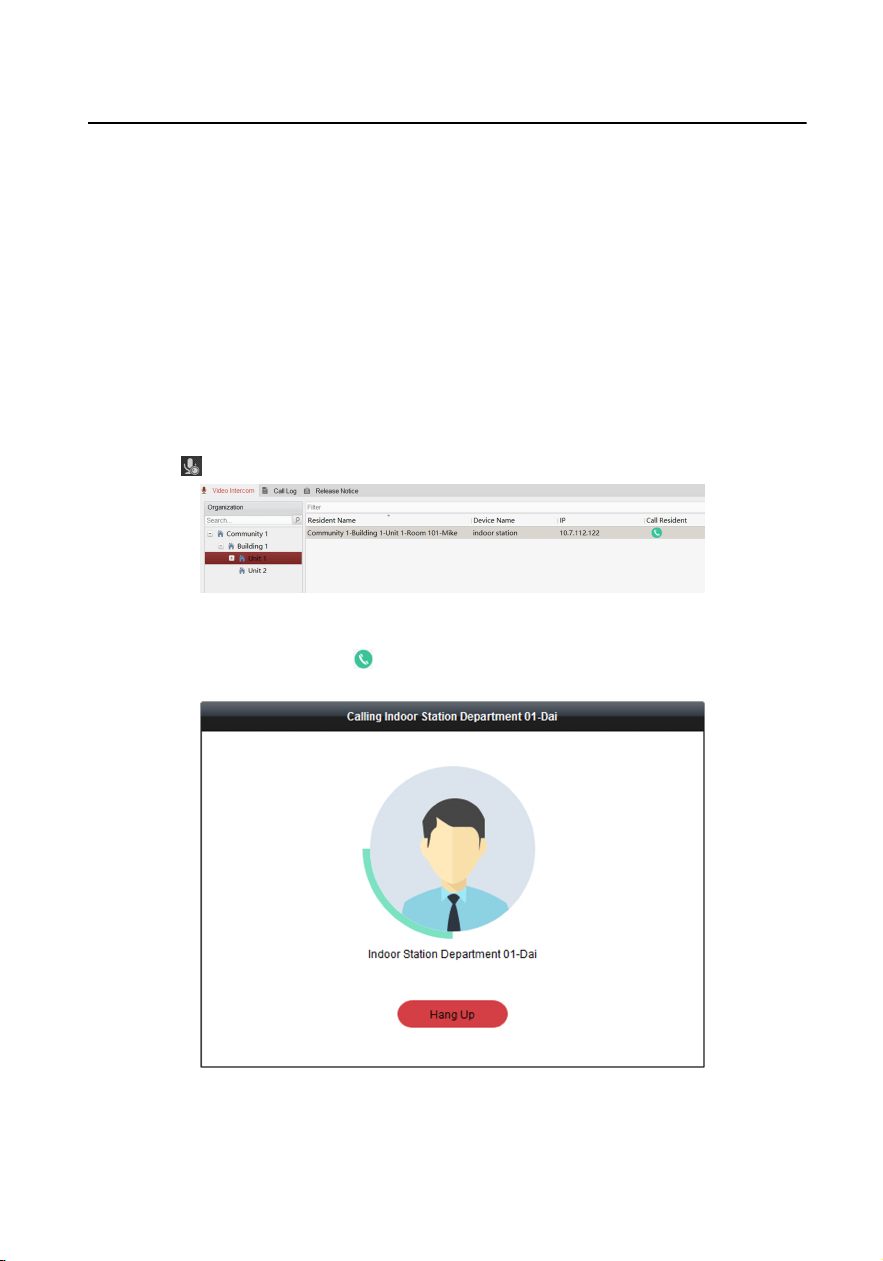
2.1 Call Indoor Staon
Steps
1.
Click
on the le icon bar to enter the Video Intercom page.
Figure 2-1 Call Indoor Staon
2.
Select a resident and click in the Call Household column to start calling the
selected resident.
Figure 2-2 Calling Indoor Staon
3.
Aer answered, you will enter the In Call window.
Network Indoor
Staon Operaon Guide
9
•
Click
to adjust the volume of the loudspeaker.
•
Click to hang up.
•
Click to adjust the volume of the microphone.
Note
•
One indoor staon can only connect with one client soware.
•
You can set the maximum ring duraon ranging from 15s to 60s, and the
maximum speaking duraon ranging from 120s to 600s via the Remote
Conguraon of indoor staon.
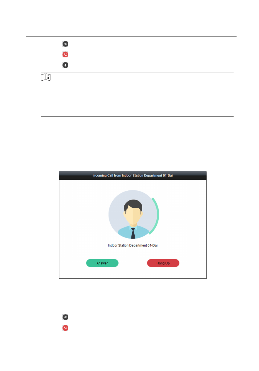
2.2 Receive Call from Indoor Staon/Door Staon
Steps
1.
Select the client soware in the indoor staon or door staon page to start
calling the client and an incoming call dialog will pop up in the client soware.
Figure 2-3 Incoming Call from Indoor Staon
2.
Click Answer to answer the call. Or click Hang Up to decline the call.
3.
Aer you answer the call, you will enter the In Call window.
•
Click to adjust the volume of the loudspeaker.
•
Click
to hang up.
Network Indoor
Staon Operaon Guide
10
•
Click
to adjust the volume of the microphone.
•
For door staon, you can click to open the door remotely.
Note
•
One video intercom device can only connect with one client soware.
•
The maximum ring duraon can be set from 15s to 60s via the Remote
Conguraon of the video intercom device.
•
The maximum speaking
duraon between indoor staon and client can be
set from 120s to 600s via the Remote
Conguraon of indoor staon.
•
The maximum speaking
duraon between door staon and client can be set
from 90s to 120s via the Remote Conguraon of door staon.
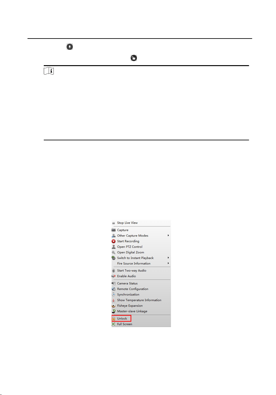
2.3 View Live Video of Door Staon and Outer Door
Staon
You can get the live view of the door staon and outer door staon in the Main View
module and control the door
staon and outer door staon remotely.
In the Main View module, double-click a door
staon or outer door staon device or
drag the device to a display window to start the live view.
Figure 2-4 Tool List
You can click Unlock on the menu to open the door remotely.
Network Indoor
Staon Operaon Guide
11
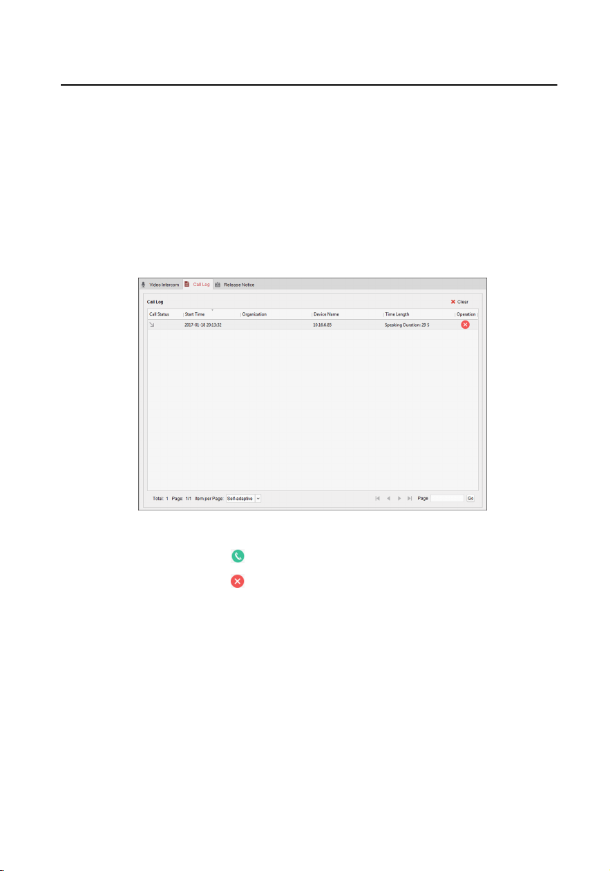
2.4 View Call Logs
You can check all the call logs, including dialed call logs, received call logs and missed
call logs. You can also directly dial via the log list and clear the logs.
Steps
1.
In the Video Intercom page, click the Call Log tab to enter the Call Log page. All
the call logs will display on this page and you can check the log
informaon, e.g.,
call status, start me, resident's organizaon and name, device name and ring or
speaking
duraon.
Figure 2-5 Call Log
2.
Oponal: Click the icon in the Operaon column to re-dial the resident.
3.
Oponal: Click the icon in the Operaon column to delete the call log. Or you
can click Clear at the upper right corner to clear all the logs.
2.5 Release
Noce
You can create dierent types of noces and send them to the residents. Four noce
types are available, including Adversing, Property, Alarm and Noce Informaon.
Steps
1.
In the Video Intercom page, click Release Noce to enter the Release Noce
page.
Network Indoor
Staon Operaon Guide
12
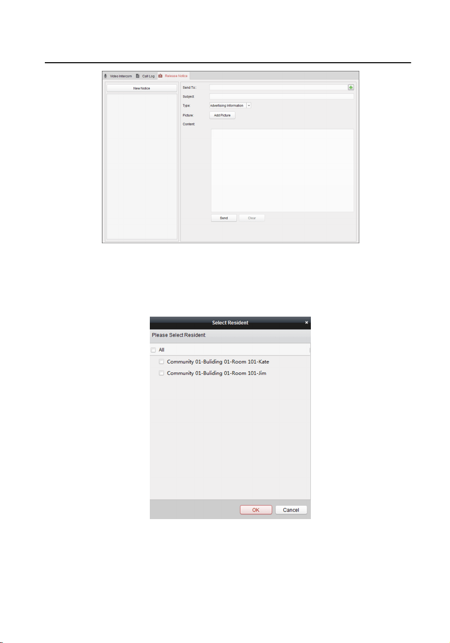
Figure 2-6 Release Noce
2.
Click New Noce on the le panel to create a new noce.
3.
Edit the noce on the right panel.
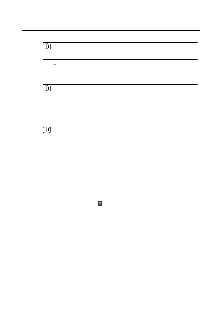
1) Click icon + on the Send To eld to pop up the Select Resident dialog.
Figure 2-7 Select Resident
2) Check the checkbox(es) to select the resident(s). Or you can check the All
checkbox to select all the added residents.
3) Click OK to save the selecon.
Network Indoor
Staon Operaon Guide
13
4) Enter the subject on the Subject eld.
Note
Up to 63 characters are allowed in the Subject eld.
5)
Click in the Type eld to unfold the drop-down list and select the noce
type.
6) Oponal: Click Add Picture to add a local picture to the noce.
Note
Up to 6 pictures in the JPGE format can be added to one noce. And the
maximum size of one picture is 512KB.
7) Enter the noce content in the Content eld.
8) Oponal: You can also click Clear to clear the edited content.
Note
Up to 1023 characters are allowed in the Content eld.
4.
Click Send to send the edited noce to the selected resident(s). The sent noce
informaon
will display on the le panel. You can click a noce to view the
details on the right panel.
2.6 Search Video Intercom
Informaon
You can search the call logs between the iVMS-4200 client soware and video
intercom devices, device unlocking logs and the sent noce informaon.
In the Access Control module, click to open the Search page.
2.6.1 Search Call Logs
Steps
1.
In the
Informaon Search page, click Call Log to enter the Call Log page.
Network Indoor
Staon Operaon Guide
14
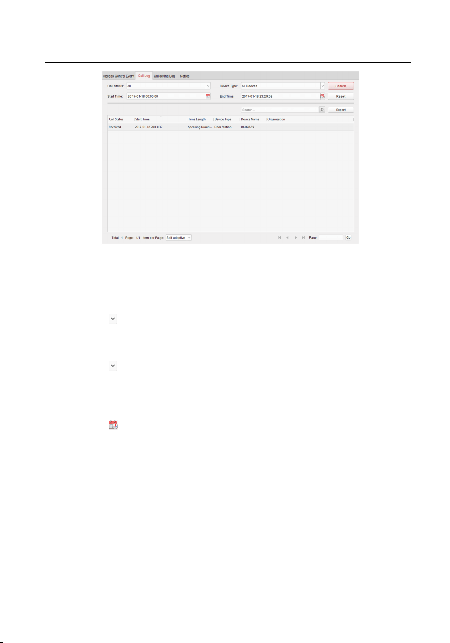
Figure 2-8 Search Call Logs
2.
Set the search condions, including call status, device type, start me and end
me.
Call Status
Click to unfold the drop-down list and select the call status as Dialed,
Received or Missed. Or select All to search logs with all statuses.
Device Type
Click to unfold the drop-down list and select the device type as Indoor
Staon, Door Staon, Outer Door Staon or Analog Indoor Staon. Or
select All Devices to search logs with all device types.
Start Time/End Time
Click to specify the start me and end me of a me period to search the
logs.
3.
Oponal: You can click Reset to reset all the congured search condions.
4.
Click Search and all the matched call logs will display on this page.
•
Check the detailed informaon of searched call logs, such as call status, ring/
speaking duraon, device name, resident organizaon, etc.
•
Input keywords in the Search eld to lter the desired log.
•
Click Export to export the call logs to your PC.
2.6.2 Search Unlocking Logs
Network Indoor Staon Operaon Guide
15
Steps
1.
In the Informaon Search page, click Unlocking Log to enter the Unlocking Log
page.
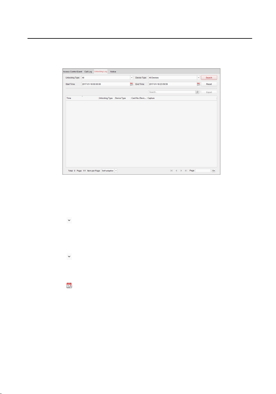
Figure 2-9 Unlocking Logs
2.
Set the search condions, including unlocking type, device type, start me and
end me.
Unlocking Type
Click
to unfold the drop-down list and select the unlocking type as Unlock
by Password, Unlock by Duress, Unlock by Card, Unlock by Resident or
Unlock by Center. Or select All to search logs with all unlocking types.
Device Type
Click to unfold the drop-down list and select the device type as Door
Staon. Or select All Devices to search logs with all device types.
Start Time/End Time
Click to specify the start me and end me of a me period to search the
logs.
3.
Oponal: You can click Reset to reset all the congured search condions.
4.
Click Search and all the matched unlocking logs will display on this page.
•
Check the detailed informaon of searched unlocking logs, such as unlocked
me, card No., device No., etc.
•
Input keywords in the Search eld to lter the searching result.
Network Indoor
Staon Operaon Guide
16
•
Click
in the Capture column to view the captured pictures.
•
Click Export to export the unlocking logs to your PC.
Note
Viewing captured picture should be supported by device.
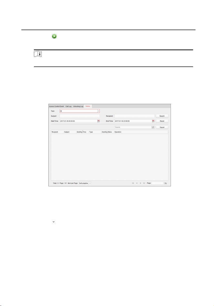
2.6.3 Search Noce
Steps
1.
In the Informaon Search page, click Noce to enter the Noce page.
Figure 2-10 Search Noce
2.
Set the search condions, including noce type, subject, recipient, start me and
end me.
Noce Type
Click to unfold the drop-down list and select the noce type as
Adversing Informaon, Property Informaon, Alarm Informaon or
Noce Informaon. Or select All to search noces with all types.
Subject
Input the keywords in the Subject
eld to search the matched noce.
Recipient
Input the recipient informaon in the Recipient eld to search the specied
noce.
Start Time/End Time
Network Indoor
Staon Operaon Guide
17
Click to specify the start me and end me of a me period to search the
noces.
3.
Oponal: You can click Reset to reset all the congured search condions.
4.
Click Search and all the matched noces will display on this page.
•
Check the detailed informaon of searched noces, such as sending me,
sending status, etc.
•
Input keywords in the Search eld to lter the searching result.
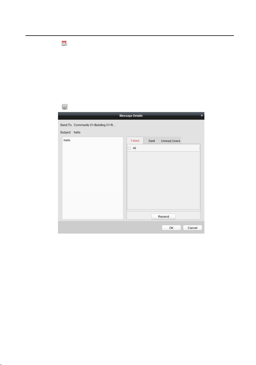
•
Click in the Operaon column to pop up Noce Details dialog.
Figure 2-11 Message Details
5.
You can view and edit the noce details, check the sending failed/sent
succeeded/unread users, and resend the noce to sending failed/unread users.
6.
Oponal: Click Export to export the noces to your PC.
Network Indoor
Staon Operaon Guide
18

UD12922B