This water heater must be installed and serviced by a qualified person.
Please leave this guide with the householder.
Owner’s Guide
and
Installation Instructions
Continuous Flow
Gas Indoor Water Heater
864, 866 series B28 models
INSTALLER:
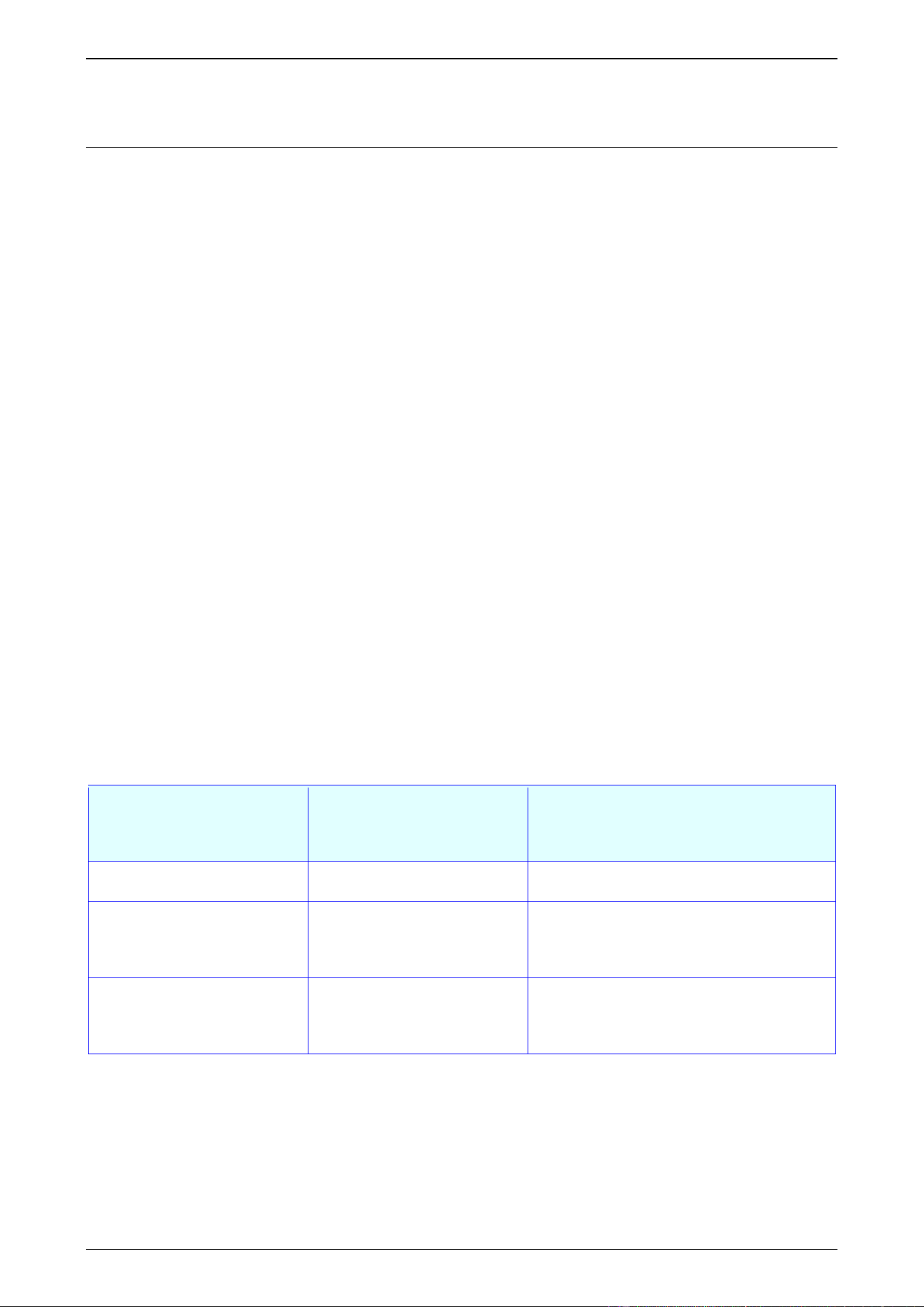
The ONLY suitable flue parts are certified Rheem coaxial flue components
carrying the following label:
DO NOT use any other type of flue parts.
Carefully follow the Installation Instructions.
OPERATOR:
DO NOT OPERATE THIS WATER HEATER:
• Unless a certified Rheem coaxial flue system, venting to the outside through a certified Rheem
terminal, is installed in accordance with the Installation Instructions.
• If a loud continued vibration occurs during operation

An electronic copy of these Owner’s Guide and Installation Instructions can be downloaded from rheem.com.au.
Rheem Australia Pty Ltd is the supplier of the Rheem range of continuous flow gas water heaters, manufactured in
Japan by Paloma Co., Ltd., a world leader in water heater technology and manufacture.
PATENTS
This water heater may be protected by one or more patents or registered designs in the name of
Rheem Australia Pty Ltd or Paloma Co., Ltd.
TRADEMARKS
®
Registered trademark of Rheem Australia Pty Ltd.
™ Trademark of Rheem Australia Pty Ltd.
Note: Every care has been taken to ensure accuracy in preparation of this publication.
No liability can be accepted for any consequences, which may arise as a result of its application.
Warning: Upon completion of the installation and commissioning of the water heater, leave this guide
with the householder or a responsible officer. DO NOT leave this guide inside of the cover of the water
heater, as it may interfere with the safe operation of the water heater or ignite when the water heater is
turned on.

3
CONTENTS
HOUSEHOLDER
This booklet contains important information about your
new water heater, including terms of the Rheem warranty.
We recommend you read pages 7 to 19,
and the terms of the Rheem warranty on pages 4 to 6.
The other pages are intended for the installer but may be of interest.
Warranty ....................................................................................................................................... 4
Safety, Warnings, Installation Notes ......................................................................................... 7
About Your Water Heater .......................................................................................................... 10
Maintenance Requirements ...................................................................................................... 15
Water Supplies........................................................................................................................... 16
Save A Service Call ................................................................................................................... 17
Installation – Water Heater ....................................................................................................... 20
Connections – Plumbing .......................................................................................................... 31
Flueing ........................................................................................................................................ 33
Connections – Electrical ........................................................................................................... 50
EZ LINK System Dual Installation ............................................................................................ 52
Commissioning.......................................................................................................................... 57
Draining The Water Heater ....................................................................................................... 66
RHEEM AUSTRALIA PTY LTD, A.B.N. 21 098 823 511
www.rheem.com.au
For Service Telephone 131 031 AUSTRALIA

4
RHEEM GAS CONTINUOUS FLOW WATER HEATER
WARRANTY – AUSTRALIA ONLY
GAS CONTINUOUS FLOW WATER HEATERS 864, 866 SERIES B28 MODELS
1. THE RHEEM WARRANTY – GENERAL
1.1 This warranty is given by Rheem Australia Pty Limited ABN 21 098 823 511 of 1 Alan Street, Rydalmere
New South Wales, the suppliers of Rheem gas continuous flow water heaters.
1.2 Rheem offer a trained and qualified national service network who will repair or replace components at
the address of the water heater subject to the terms of the Rheem warranty. Rheem Service, in addition
can provide preventative maintenance and advice on the operation of your water heater. The Rheem
Service contact number is 131031, with Contact Centre personnel available 24 hours, 7 days a week to
take your call and if necessary to arrange a service call for during normal working hours Monday to
Friday (hours subject to change).
1.3 For details about this warranty, you can contact us on 131031 or by email at
[email protected] (not for service bookings).
1.4 The terms of this warranty and what is covered by it are set out in sections 2 and 3 and apply to water
heaters manufactured from the 1
st
April 2024.
1.5 If a subsequent version of this warranty is published, the terms of that warranty and what is covered by
it will apply to water heaters manufactured after the date specified in the subsequent version.
2. TERMS OF THE RHEEM WARRANTY AND EXCLUSIONS TO IT
2.1 The decision of whether to repair or replace a faulty component is at Rheem’s sole discretion.
2.2 If you require a call out and we find that the fault is not covered by the Rheem warranty, you are
responsible for our standard call out charge. If you wish to have the relevant component repaired or
replaced by Rheem, that service will be at your cost.
2.3 Where a failed component or cylinder is replaced under this warranty, the balance of the original
warranty period will remain effective. The replacement does not carry a new Rheem warranty.
2.4 the water heater is installed outside the boundaries of a metropolitan area as defined by Rheem or
further than 25 km from either a regional Rheem branch office or an Accredited Rheem Service Agent's
office, the cost of transport, insurance and travelling between the nearest branch office or Rheem
Accredited Service Agent’s office and the installed site shall be the owner’s responsibility.
2.5 Where the water heater is installed in a position that does not allow safe or ready access, the cost of
that access, including the cost of additional materials handling and/or safety equipment, shall be the
owner’s responsibility. In other words, the cost of dismantling or removing cupboards, doors or walls
and the cost of any special equipment to bring the water heater to floor or ground level or to a serviceable
position is not covered by this warranty.
2.6 This warranty only applies to the original and genuine Rheem water heater in its original installed location
and any genuine Rheem replacement parts.
2.7 The Rheem warranty does not cover faults that are a result of:
a) Accidental damage to the water heater or any component (for example: (i) Acts of God such as
floods, storms, fires, lightning strikes and the like; and (ii) third party acts or omissions).
b) Misuse or abnormal use of the water heater.
c) Installation not in accordance with the Owner’s Guide and Installation Instructions or with relevant
statutory and local requirements in the State or Territory in which the water heater is installed.
d) Connection at any time to a water supply that does not comply with the water supply guidelines as
outlined in the Owner’s Guide and Installation Instructions.
RHEEM GAS CONTINUOUS FLOW WATER HEATER
WARRANTY – AUSTRALIA ONLY
5
GAS CONTINUOUS FLOW WATER HEATERS 864, 866 SERIES B28 MODELS
e) Repairs, attempts to repair or modifications to the water heater by a person other than Rheem
Service or a Rheem Accredited Service Agent.
f) Faulty plumbing or faulty gas or power supply.
g) Failure to maintain the water heater in accordance with the Owner's Guide and Installation
Instructions.
h) Transport damage.
i) Fair wear and tear from adverse conditions (for example, corrosion).
j) Cosmetic defects.
k) Ice formation in the waterways of a water heater: where the electricity supply has been switched off
or has failed and the water heater has not been drained in accordance with the instructions; or due
to an ambient temperature below -20°C (including wind chill factor).
2.8 Subject to any statutory provisions to the contrary, this warranty excludes any and all claims for damage
to furniture, carpet, walls, foundations or any other consequential loss either directly or indirectly due to
leakage from the water heater, or due to leakage from fittings and/ or pipe work of metal, plastic or other
materials caused by water temperature, workmanship or other modes of failure.
2.9 If the water heater is not sized to supply the hot water demand in accordance with the guidelines in the
Rheem water heater literature, any resultant fault will not be covered by the Rheem warranty.
3. WHAT IS COVERED BY THE RHEEM WARRANTY
FOR THE WATER HEATERS DETAILED IN THIS DOCUMENT
3.1 Rheem will repair or replace a faulty component of your water heater if it fails to operate in accordance
with its specifications as follows:
What components
are covered
The period from the date of
installation in which the
fault must appear in order to
be covered
What coverage you receive
All components
Year 1
Repair and/or replacement of the faulty
component, free of charge, including labour.
All components
(only if the water heater is
installed in a single-family
domestic dwelling)
Years 2 & 3
Repair and/or replacement of the faulty
component, free of charge, including labour.
The heat exchanger
(only if the water heater is
installed in a single-family
domestic dwelling)
Years 4 to 15
Replacement heat exchanger, free of
charge. Installation and repair labour costs
are the responsibility of the owner.

RHEEM GAS CONTINUOUS FLOW WATER HEATER
WARRANTY – AUSTRALIA ONLY
6
GAS CONTINUOUS FLOW WATER HEATERS 864, 866 SERIES B28 MODELS
4. ENTITLEMENT TO MAKE A CLAIM UNDER THIS WARRANTY
4.1 To be entitled to make a claim under this warranty you need to:
a) Be the owner of the water heater or have consent of the owner to act on their behalf.
b) Contact Rheem Service without undue delay after detection of the defect and, in any event, within
the applicable warranty period.
4.2 You are not entitled to make a claim under this warranty if your water heater:
a) Does not have its original serial numbers or rating labels.
b) Is not installed in Australia.
5. HOW TO MAKE A CLAIM UNDER THIS WARRANTY
5.1 If you wish to make a claim under this warranty, you need to:
a) Contact Rheem on 131031 in Australia and provide owner’s details, address of the water heater, a
contact number and date of installation of the water heater or if that’s unavailable, the date of
manufacture and serial number (from the rating label on the water heater).
b) Rheem will arrange for the water heater to be tested and assessed on-site.
c) If Rheem determines that you have a valid warranty claim, Rheem will repair or replace the water
heater in accordance with this warranty.
5.2 Any expenses incurred in the making of a claim under this warranty will be borne by you.
6. THE AUSTRALIAN CONSUMER LAW
6.1 In Australia, our goods come with guarantees that cannot be excluded under the Australian Consumer
Law. You are entitled to a replacement or refund for a major failure and for compensation for any other
reasonably foreseeable loss or damage. You are also entitled to have the goods repaired or replaced if
the goods fail to be of acceptable quality and the failure does not amount to a major failure.
6.2 The Rheem warranty (set out above) is in addition to any rights and remedies that you may have under
the Australian Consumer Law.

7
SAFETY, WARNINGS, INSTALLATION NOTES
It is important you read the following safety and warnings information.
SAFETY AND WARNINGS
• The water heater heats the water to the preset outlet temperature setting if a temperature controller is not
installed. The outlet temperature setting can be up to 75°C for an 864 series water heater or up to 50°C
for an 866 series water heater. If an 864 series water heater is installed as part of a solar water heater
system, the system can deliver water at temperatures from 58°C up to 80°C and possibly higher
depending upon the model of solar water heater installed.
These temperatures from an 864 series water heater are sufficiently hot to cause severe scalding. Water
at this temperature may have been plumbed to fixtures where water hotter than 50°C is allowed, such as
the kitchen and laundry.
Refer to:
◼ “How Hot Should the Water Be?” on page 11, and
◼ “Hotter Water Increases the Risk of Scald Injury” on page 11.
• This water heater is only intended to be operated by persons who have the experience or the knowledge
and the capabilities to do so.
• This water heater is not intended to be operated by persons with reduced physical, sensory or mental
capabilities i.e. the infirm, or by children. Children should be supervised to ensure they do not interfere
with or play with or at the water heater.
• If the power supply cord or plug is damaged, it must be replaced by a qualified person in order to avoid a
hazard. The power supply cord and plug must be replaced with a genuine replacement part available from
Rheem. Phone Rheem Service or their nearest Accredited Service Agent to arrange for an inspection.
• The power lead from the water heater must be plugged into a weatherproof electrical outlet. Take care
not to touch the power plug with wet hands.
• The water heater uses 220 - 240 V a.c. electrical power for operation of the control systems and the
combustion fan. The removal of the front panel will expose 220 - 240 V a.c. wiring. It must only be removed
by a qualified person. Do not operate the water heater with the front panel removed.
• This water heater is supplied with temperature sensors, a FlameSafe
®
protection system and a pressure
relief valve. These devices must not be tampered with or removed. The water heater must not be operated
unless each of these devices is fitted and is in working order.
The Rheem warranty may not cover faults if safety devices or the relief valve are tampered with or
if the installation is not in accordance with these instructions.
• Temperature controllers must not be fitted to this water heater (864 series) if it is installed as an in-series
gas booster with a solar water heater system because water at a temperature much higher than the
controller setting can be delivered. If a solar water heater is installed to an existing water heater
installation, then all controllers must be disconnected and removed.
• For continued safety of this water heater it must be installed, operated and maintained in accordance with
the Owner’s Guide and Installation Instructions.
• Servicing of the water heater must only be carried out by qualified personnel. Phone Rheem Service or
their nearest Accredited Service Agent.
• Do not modify this water heater.
• Switch off the electrical supply at the power outlet to the water heater prior to performing general
maintenance. This will prevent the water heater from operating while you clean or spray around the water
heater.
Refer to “General Maintenance” on page 15 for additional information.
SAFETY, WARNINGS, INSTALLATION NOTES
8
• Do not spray aerosols in the vicinity of this water heater while it
is in operation. Propellants and gases in many aerosol sprays
contain hydrocarbons which are flammable. Gases from aerosol
sprays may also become corrosive when drawn into a flame.
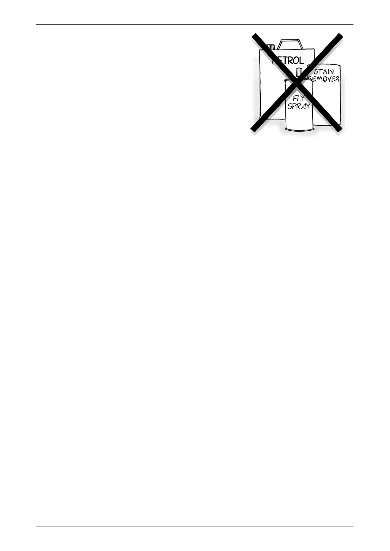
• Do not use or store flammable materials in or near this water
heater. Flammable liquids (such as petrol), combustible
materials (such as newspapers) and similar articles must be kept
well away from the water heater and the flue terminal.
• Do not store swimming pool chemicals, household cleaners,
etc., near the water heater.
• Do not place articles on or against this water heater, or in contact
with the flue terminal. Ensure the flue terminal is not obstructed
in any way at any time.
• The water heater has a frost protection system to protect against damage by preventing ice forming in the
waterways of the water heater, in the event of freezing conditions occurring. The frost protection system
will be rendered inoperable if electrical power is not available at the water heater. If it is necessary to
switch the power off to the water heater and there is a risk of freezing, then it is necessary to drain the
water heater.
Refer to:
▪ “Frost Protection” on page 12, and
▪ “Draining the Water Heater” on page 13.
INSTALLATION NOTES
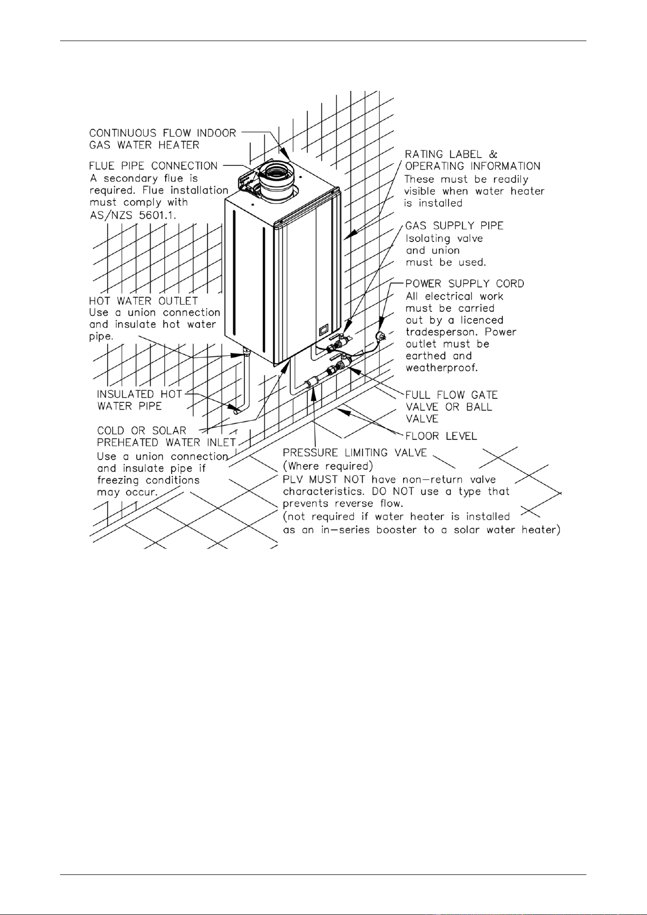
This water heater must be installed:
• by a qualified person,
• in accordance with the installation instructions,
• in compliance with the Plumbing Code of Australia (PCA) and Plumbing Standard AS/NZS 3500.4,
▪ This water heater is designed for indoor installation only.
▪ This water heater is intended to be permanently connected to the water mains and not connected by
a hose-set. A braided flexible hose or semi-flexible connector may be used for connection to the water
heater, where permitted by AS/NZS 3500.4.
• in compliance with the Gas Installations Standard AS/NZS 5601.1,
• in compliance with all local codes and regulatory authority requirements.
Installation and commissioning requirements and details for the installing plumber and licensed electrical
worker are contained on pages 20 to 66.

SAFETY, WARNINGS, INSTALLATION NOTES
9
Mains pressure water supply
The water heater is designed to operate at mains pressure by connecting directly to the mains water supply.
The maximum mains water supply pressure for the water heater is 1,000 kPa. If the mains supply pressure in
your area exceeds 1,000 kPa, an approved pressure limiting valve that does not have non-return valve
characteristics (such as an RMC PSL series valve) must be installed.
A minimum water supply pressure of 120 kPa is required to achieve the rated flow and performance of the
water heater.
Refer to “Mains Water Supply” on page 22 for additional information.
Mounting of the water heater
This water heater must be installed vertically upright with the water, gas and power connections on the
underside, pointing toward the ground. The back of the water heater can be either against a wall or supported
by a frame. The water heater must be well secured to the wall or frame using two fasteners, suitable for the
wall or frame type, each at the top and bottom of the unit.
Refer to the note on page 21 for additional information.
10
ABOUT YOUR WATER HEATER
WATER HEATER APPLICATION
This water heater is designed for use in a single family domestic dwelling for the purpose of heating potable
water. Its use in an application other than this may shorten its life.
MODEL TYPE
The Rheem
®
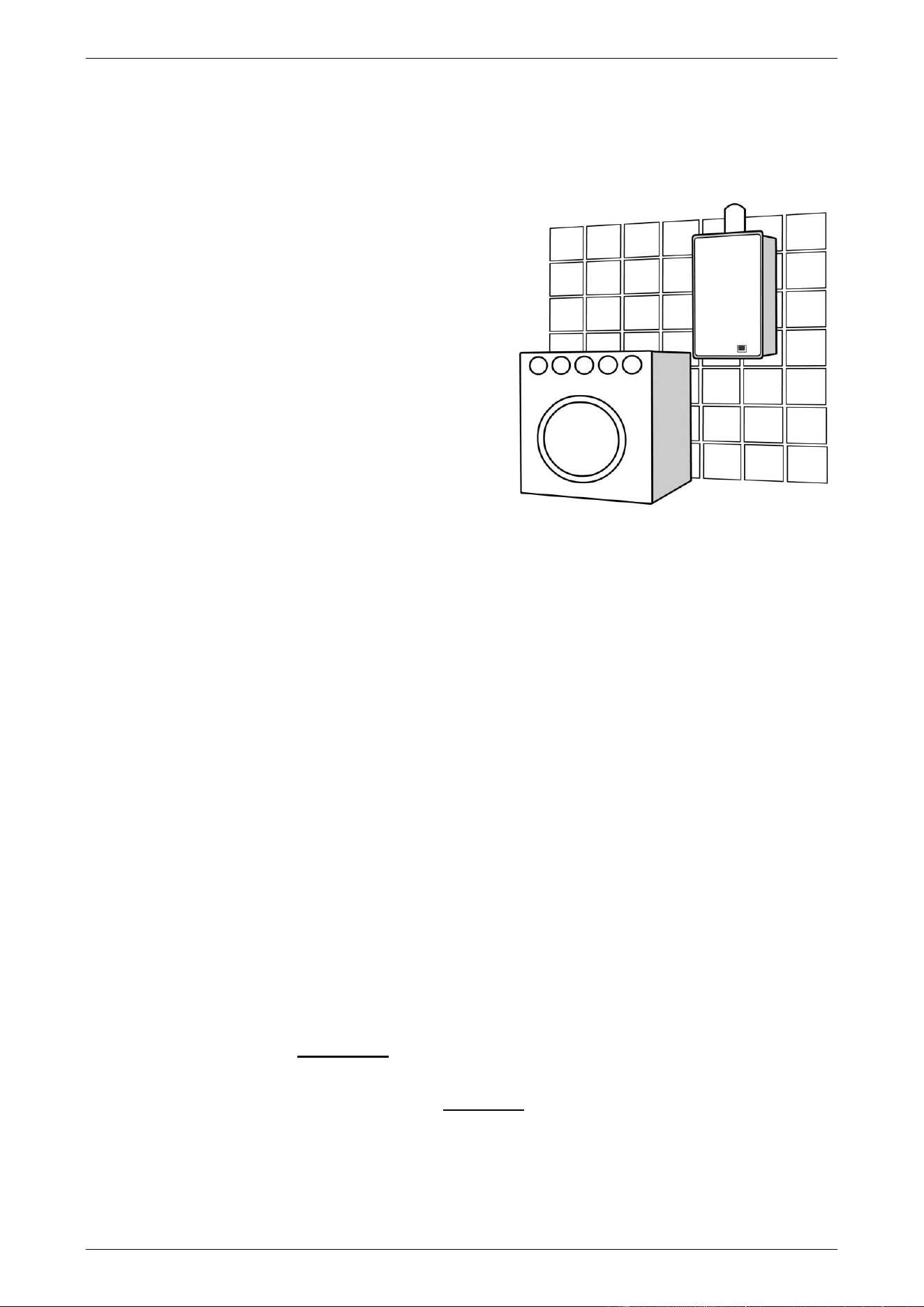
gas continuous flow water heater model you have chosen is for
indoor installation only.
The water heater has a maximum preset outlet temperature setting of:
• 864 series 75°C
• 866 series 50°C
Note: The 866 series water heater is marked “THIS APPLIANCE DELIVERS
WATER NOT EXCEEDING 50°C IN ACCORDANCE WITH AS 3498” on the
front panel.
• This model must not be installed as an in-series gas booster to a solar
water heater, as water temperature greater than 50°C can be delivered
from the water heater contravening its compliance to AS 3498.
WATER HEATER OPERATION
The water heater operates automatically, heating water as it passes through the water heater. When a hot tap
is opened, the gas burners ignite to provide immediate heating of the water. The heat produced by the burner
is transferred to the water through the heat exchanger. The water is heated to a constant temperature by the
automatic adjustment of the gas supply to the burner to suit the water flow rate. The gas burners extinguish
when the hot tap is closed.
Automatic safety controls are fitted to the water heater to provide safe and efficient operation. In the event of
a power supply interruption, such as a blackout or brownout, when power is restored to the water heater, it will
initialise and be ready for use.
USER TEMPERATURE CONTROL
Temperature Controllers
The Rheem 864 and 866 series may be installed with one or more user adjustable Standard temperature
controllers, which allow you to choose the most suitable water temperature of the delivered water from the
outlet of the water heater for your hot water needs. They are the Kitchen controller, Bathroom 1 controller and
the Bathroom 2 controller.
Temperature controllers are only suitable for either a single water heater installation or a dual water heater
installation using the EZ Link system. They are not suitable if multiple water heaters are manifolded together.
Other manufacturers’ controllers are not suitable to and cannot be installed with this water heater.
Warning: Temperature controllers must not be fitted to this water heater (864 series) if it is installed as an
in-series gas booster with a solar water heater system because water at a temperature much higher than the
controller setting can be delivered. If a solar water heater is installed to an existing water heater installation,
then all controllers must be disconnected and removed.
Refer to the Rheem website for the Owner’s Guide and Installation Instructions for the Standard Rheem
Controllers. Visit www.rheem.com.au/rheem/help#guides.
ABOUT YOUR WATER HEATER
11
HOW HOT SHOULD THE WATER BE?
If a controller is not installed, the water heater heats the water to the preset outlet temperature setting. The
factory preset outlet temperature setting is:
• 864 series 60°C
• 866 series 50°C
Note: The preset outlet temperature setting of this water heater
cannot be adjusted by the householder. The setting can only
be adjusted by the installer, Rheem Service or their nearest
Accredited Service Agent.
Note: Australian Standard AS 3498 requires that a water
heater provides the means to inhibit the growth of Legionella
bacteria in potable water. When the 864 series water heater is
used as an in-series booster for a solar water heater it can
satisfy the AS 3498 requirements provided it is energised, the
booster preset outlet temperature setting is at least 70°C, and
that a remote temperature controller is not used.
Warning: Temperature controllers must not be fitted to
this water heater (864 series) if it is installed as an in-series
gas booster with a solar water heater system because water
at a temperature much higher than the controller setting can
be delivered. If a solar water heater has been installed to an
existing water heater installation, then all controllers must be
disconnected and removed.
If this water heater is installed as part of a solar water heater system, the system can deliver water at
temperatures from 58°C up to 80°C and possibly higher depending upon the model of solar water heater
installed.
HOTTER WATER INCREASES THE RISK OF SCALD INJURY
Warning: This water heater can deliver water at temperatures which can cause scalding.
Check the water temperature before use, such as when entering a shower or filling a bath or basin, to ensure
it is suitable for the application and will not cause scald injury.
864 series – Hot Water Outlet
Depending upon its preset outlet temperature setting, an 864 series water heater can deliver hot water at a
temperature up to 75°C when no temperature controller is installed and 60°C when a temperature controller is
installed. These temperatures are sufficiently hot to cause severe scalding. A model used as a booster to a
solar water heater could on occasion deliver hot water exceeding 75°C. Water at these temperatures may
have been plumbed to fixtures where water hotter than 50°C is allowed, such as the kitchen and laundry.
We recommend and it may be required by regulations that an approved temperature limiting device be fitted
into the hot water pipe work to the bathroom and ensuite when an 864 series water heater is installed. This
will keep the water temperature below 50°C at the bathroom and ensuite. The risk of scald injury will be reduced
and if no controllers are installed and the preset outlet temperature setting has not been adjusted below 55°C
or if a Kitchen controller is installed, still allow hotter water to the kitchen and laundry.
866 series – 50°C Limited Outlet
An 866 series water heater delivers water not exceeding 50°C in accordance with AS 3498. The risk of scald
injury will be reduced.
There is no need to fit a temperature limiting device to satisfy the requirements of the Plumbing Code of
Australia if an 866 series water heater is installed and serving an application where 50°C is the maximum
permissible hot water temperature at the outlet of a fixture used primarily for personal hygiene, such as in a
bathroom or ensuite.
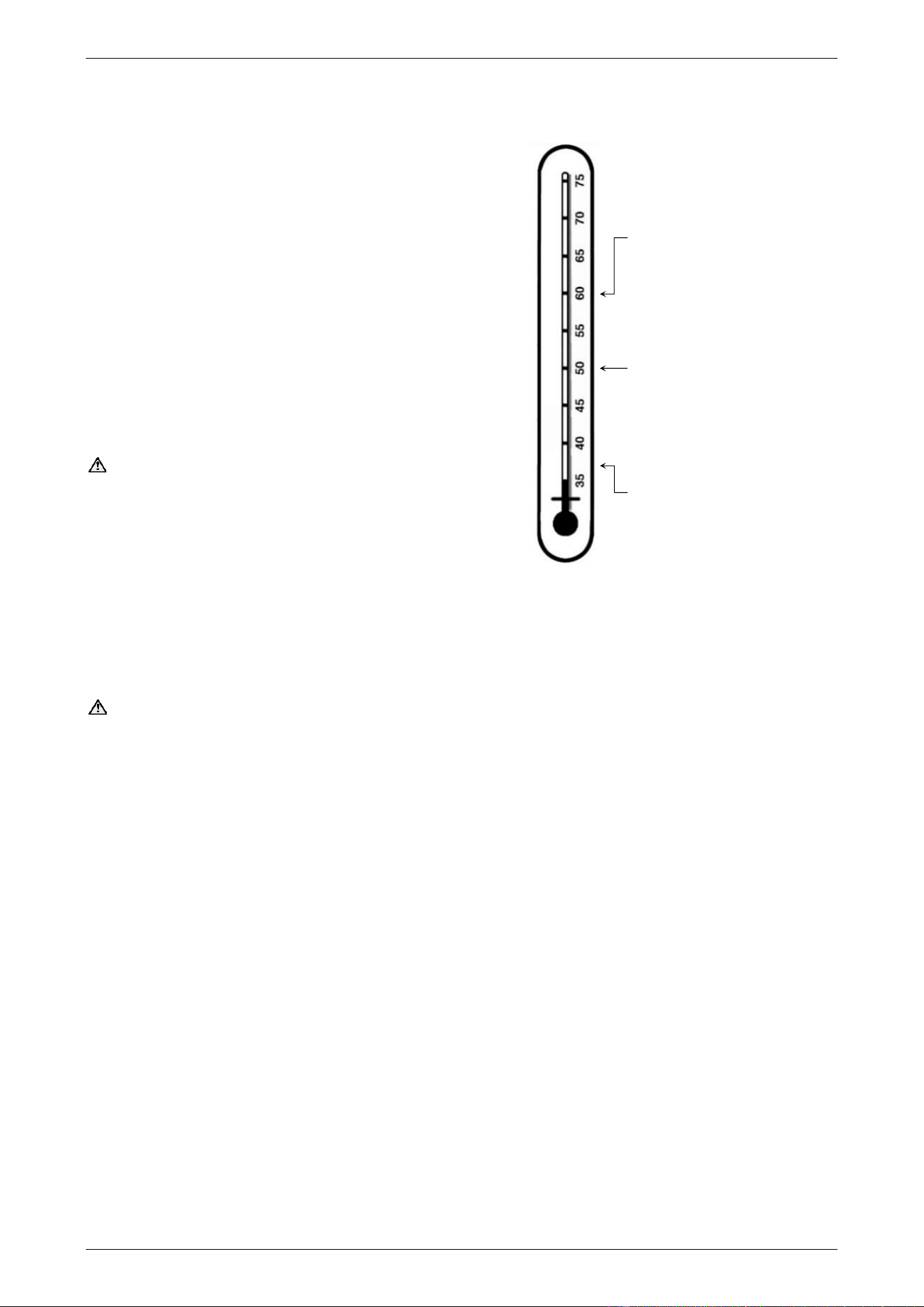
maximum recommended supply
temperature to bathrooms and
ensuites.
maximum Bathroom controller
temperature setting 864 series.
maximum Kitchen and Bathroom
controller temperature setting
866 series.
maximum Kitchen controller
temperature setting 864 series
minimum Kitchen and Bathroom
controller temperature setting

ABOUT YOUR WATER HEATER
12
GAS BOOSTING FOR A SOLAR WATER HEATER
The 864 series water heater may be installed as an in-series gas booster to a solar water heater.
Water stored in the solar storage tank passes through the in-series gas booster when a hot tap is opened. The
in-series gas booster is for heating water at times of low solar energy gain, such as during cloudy or rainy
weather, or during colder months.
The in-series gas booster operates automatically. When the solar heated water temperature is below 58°C,
the in-series gas booster heats the water to its preset outlet temperature setting.
Solar heated water can reach temperatures up to 70°C to 80°C for a Premier Loline and Loline pumped system
and possibly higher for a Hiline and Premier Hiline thermosiphon system. When the solar heated water
temperature is 58°C or higher, the flow passes through the in-series gas booster without boosting.
For information relating to the function and operation of the solar water heater, refer to the Owner’s Guide and
Installation Instructions supplied with the solar water heater.
REDUCED HOT WATER FLOW WHEN HEAT EXCHANGER IS COLD
At a cold start-up, i.e. when the water heater has not operated for some time (which is most often first thing in
the morning), the initial flow of hot water may be reduced for a period of 5-10 seconds while the heat exchanger
warms up. This is both an energy and water saving feature of this water heater. Once the heat exchanger
has warmed up the hot water flow will increase and remain at normal flow levels. This feature will only occur
at a cold start-up and not when the heat exchanger is already warm from a recent use of hot water.
FROST PROTECTION
The water heater has a frost protection system. The frost protection system will protect the water heater from
damage, by preventing ice forming in the waterways of the water heater, in the event of freezing conditions
occurring.
Notes
• The frost protection system will be rendered inoperable if electrical power is not available at the water
heater. Damage caused by freezing due to the unavailability of power at the water heater is not covered
by the Rheem warranty (refer to “Terms of the Rheem Warranty” on page 4).
• If it is necessary to switch the power off to the water heater and there is a risk of freezing, then it is
necessary to drain the water heater (refer to “Draining the Water Heater” on page 13).
• Pipe work to and from the water heater must be adequately insulated to prevent freezing.
• The water heater is not suitable for installation in areas where the ambient temperature falls below -20°C
(including wind chill factor).
• Refer to “Terms of the Rheem Warranty” on page 4.
PRECAUTIONS
The water heater must be maintained in accordance with the Owner’s Guide and Installation Instructions. Refer
to “General Maintenance” on page 15 and “Major Service Every Five Years” on page 15.
If this water heater is to be used where an uninterrupted hot water supply is necessary for your application or
business you should ensure that you have back-up redundancy within the hot water system design. This should
ensure the continuity of hot water supply in the event that this water heater were to become inoperable for any
reason. We recommend you seek advice from a plumber or specifier about your needs and building back-up
redundancy into your hot water supply system.
ABOUT YOUR WATER HEATER
13
TO TURN OFF THE WATER HEATER
If it is necessary to turn off the water heater:
• Turn off the controller(s) (if fitted) by pressing the on / off ( ) button.
The on / off operating light will go out and the priority light, if it is on, will go out.
• Switch off the electrical supply at the power outlet to the water heater if there is no risk of freezing
conditions occurring (refer to note below).
• Close the gas isolation valve at the inlet to the water heater.
• Close the cold water isolation valve at the inlet to the water heater.
Note: If there is a risk of freezing conditions, the electrical supply to the water heater should not be switched
off unless the water heater is drained, otherwise damage could result (refer to “Frost Protection” on page 12
and “Draining the Water Heater” on page 13).
TO TURN ON THE WATER HEATER
• Screw in the drain plugs at the cold water inlet and hot water outlet of the water heater if the water heater
has been drained.
• Open all of the hot taps in the house (don’t forget the shower).
• Open the cold water isolation valve fully at the inlet to the water heater.
Air will be forced out of the taps.
• Close each tap as water flows freely from it.
• Open the gas isolation valve fully at the inlet to the water heater.
• Plug in the power supply cord at the power outlet.
• Switch on the electrical supply at the power outlet to the water heater.
• Turn on a controller, if one is fitted, by pressing the on / off ( ) button.
The on / off operating light and the priority light will both glow.
The water heater will operate automatically when you open a hot tap.
DRAINING THE WATER HEATER
• Turn off the water heater (refer to “Turn Off The Water Heater” on page 13).
• Open a hot tap (preferably the shower outlet).
• Unscrew the two drain plugs, one each at the cold water inlet and hot water outlet (864 series model) or
50°C limited outlet (866 series model), on the underside of the water heater.
Water will drain from the water heater.
• When water stops flowing from the water heater, close the hot tap.
Note: It is recommended not to screw the drain plugs back in, until the water heater is to be turned on again.
HOT WATER OUTLET COLD WATER INLET
in use
priority
X 10L
88
°C
in use
priority
X 10L
88
°C

ABOUT YOUR WATER HEATER
14
CIRCULATED HOT WATER FLOW AND RETURN SYSTEM
A Rheem 864B28 model continuous flow water heater can be installed as part of a circulated hot water flow
and return system in a building. Refer to “Circulated Hot Water Flow and Return System” on page 25 for further
information and notes on this type of installation.
GOING ON HOLIDAYS
If you are going on holidays, it is not necessary to turn the water heater off. If it is necessary to turn off the
water heater, refer to “To Turn Off The Water Heater” on page 13.
VICTORIAN CUSTOMERS
Notice to Victorian Customers from the Victorian Building Authority. This water heater must be installed by a
licensed person as required by the Victorian Building Act 1993.
Only a licensed person will give you a Compliance Certificate, showing that the work complies with all the
relevant Standards. Only a licensed person will have insurance protecting their workmanship for 6 years. Make
sure you use a licensed person to install this water heater and ask for your Compliance Certificate.
DOES THE WATER CHEMISTRY AFFECT THE WATER HEATER?
The water heater is suitable for most public water supplies, however some water chemistries may have
detrimental effects on the water heater, its components and fittings. Refer to “Water Supplies” on page 16.
If you are in a known harsh water area or you are not sure of your water chemistry, have your water checked
against the conditions described on page 16.
HOW LONG WILL THE WATER HEATER LAST?
The water heater is supported by a manufacturer’s warranty (refer to page 4). There are a number of factors
that will affect the length of service the water heater will provide. These include but are not limited to the water
chemistry, the water pressure, the water temperature (inlet and outlet) and the water usage pattern. Refer to
“Precautions” on page 12.
15
MAINTENANCE REQUIREMENTS
GENERAL MAINTENANCE
General maintenance can be performed by the dwelling occupant. It is recommended general maintenance
be conducted every six (6) months or more regularly as required.
Switch off the electrical supply at the power outlet to the water heater prior to performing general maintenance.
This will prevent the water heater from operating while you clean or spray around the water heater. Switch on
the electrical supply at the power outlet to the water heater when finished performing the general maintenance.
The general maintenance includes:
• The jacket of the water heater can be cleaned with a soft cloth and warm mild soapy water if required.
Under no circumstances should abrasive materials or powders be used.
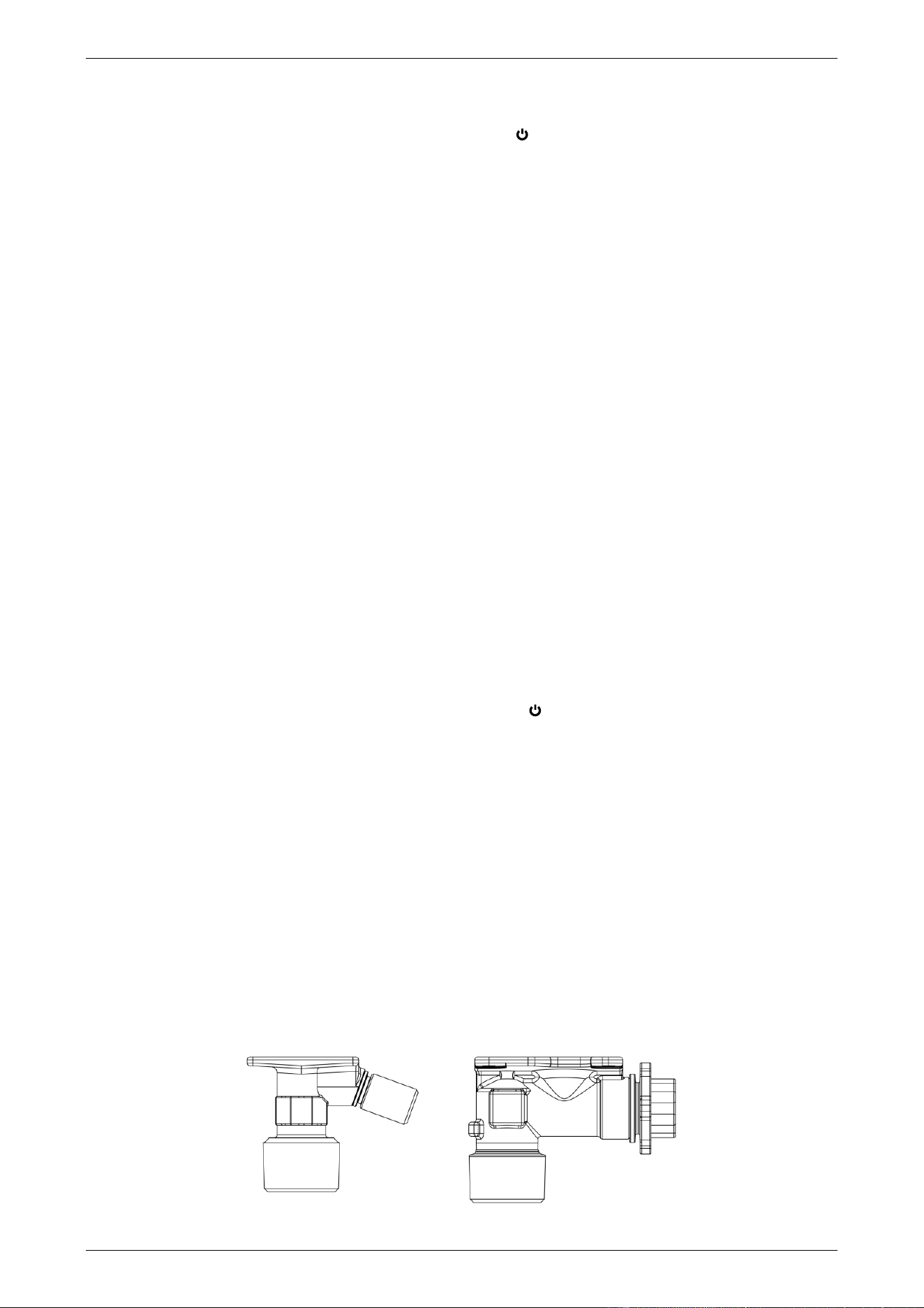
• Condensate Trap – Check a condensate trap, if one is installed, to ensure it is filled with water. If a trap is
dry or the water level is low, then a trap must be refilled.
A condensate trap may be installed as part of a condensate drain line from the secondary flue system.
▪ To check and / or refill a trap with water, remove the clamp securing the hose of the condensate trap
to the spigot on the flue outlet. Remove the hose from the spigot and fill the condensate trap with
water. Reconnect the hose to the spigot. Ensure the hose is not kinked when reconnected.
Warning: Failure to fill a Condensate Trap with water may cause flue gases to escape through the
drain line.
• Inspect around the flue terminal of the water heater for plant growth.
▪ Trim back any shrubs, bushes or other plants which have encroached around the flue terminal.
Plant growth across flue terminal can interfere with the performance of the water heater.
MAJOR SERVICE EVERY FIVE YEARS
For safe and efficient operation, it is recommended a major service be conducted on the water heater every
five (5) years.
Warning: Servicing of a water heater must only be carried out by qualified personnel. Phone Rheem
Service or their nearest Accredited Service Agent.
Note: The major service and routine replacement of any components, if required, are not included in the
Rheem warranty. A charge will be made for this work. Only genuine replacement parts should be used on this
water heater. The major service includes the following actions:
• Check and if necessary adjust the gas pressure.
• Check the operation of and clean the burner.
• Check the water level in the condensate trap (if one is installed).
• Check and clean the line strainer.
• Visually check the unit for any potential problems.
• Inspect all connections.
16
WATER SUPPLIES
This water heater must be installed in accordance with this advice to be covered by the Rheem
warranty.
This water heater is manufactured to suit the water conditions of most public reticulated water supplies.
However, there are some known water chemistries which can have detrimental effects on the water heater
and its operation and / or life expectancy. If you are unsure of your water chemistry, you may be able to obtain
information from your local water supply authority. This water heater should only be connected to a water
supply which complies with these guidelines for the Rheem warranty to apply.
CHANGE OF WATER SUPPLY
The changing or alternating from one water supply to another can have a detrimental effect on the operation
and / or life expectation of a heat exchanger in a continuous flow water heater.
Where there is a changeover from one water supply to another, e.g., a rainwater tank supply, bore water
supply, desalinated water supply, public reticulated water supply or water brought in from another supply, then
water chemistry information should be sought from the supplier or it should be tested to ensure the water
supply meets the requirements given in these guidelines for the Rheem warranty to apply.
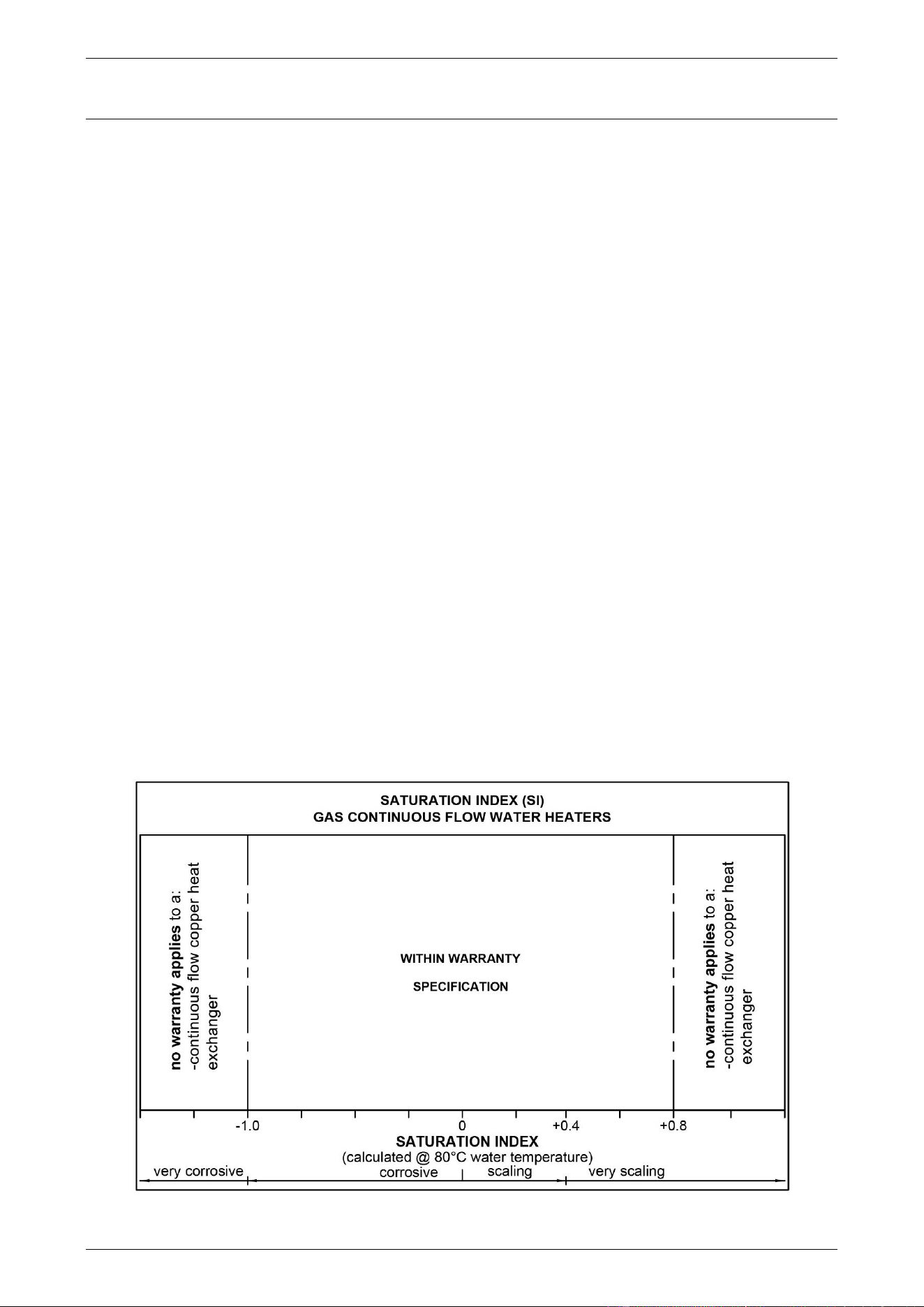
SATURATION INDEX
The saturation index (SI) is used as a measure of the water’s corrosive or scaling properties. The saturation
index figures stated are calculated using a water temperature of 80°C.
In a corrosive water supply, the water can attack copper parts and cause them to fail. Where the saturation
index is less than –1.0, the water is very corrosive and the Rheem warranty does not apply to a copper heat
exchanger in a continuous flow water heater.
In a scaling water supply calcium carbonate is deposited out of the water onto any hot metallic surface. Where
the saturation index exceeds +0.80, the Rheem warranty does not apply to a copper heat exchanger in a
continuous flow water heater.
Water which is scaling may be treated with a water softening device to reduce the saturation index of the water.
Refer to the Saturation Index chart on page 16.
17
SAVE A SERVICE CALL
Check the items below before making a service call. You will be charged for attending to any condition or fault,
which is not related to manufacture or failure of a part (refer to “Terms of the Rheem Warranty” on page 4).
NO DISPLAY ON THE CONTROLLER
• Is the controller turned on?
Press the on / off ( ) button on the controller.
• Is the water heater plugged in and the power outlet switched on?
• Is power available in the house?
Try using another electrical appliance.
COLD WATER FROM THE HOT TAP
• Is the controller turned on?
Press the on / off ( ) button on the controller.
• Close the hot tap, wait 10 seconds and open the hot tap again.
• Is the hot tap open enough?
The burners will not light if the flow rate is less than 1.5 L / min.
• Is the water heater plugged in and the power outlet switched on?
• Is power available in the house?
Try using another electrical appliance.
• Is the isolation valve in the gas line open?
• Is there a gas supply to the rest of the house?
Try lighting another gas appliance.
• Has the gas line been purged of air after installation?
Refer to a plumber.
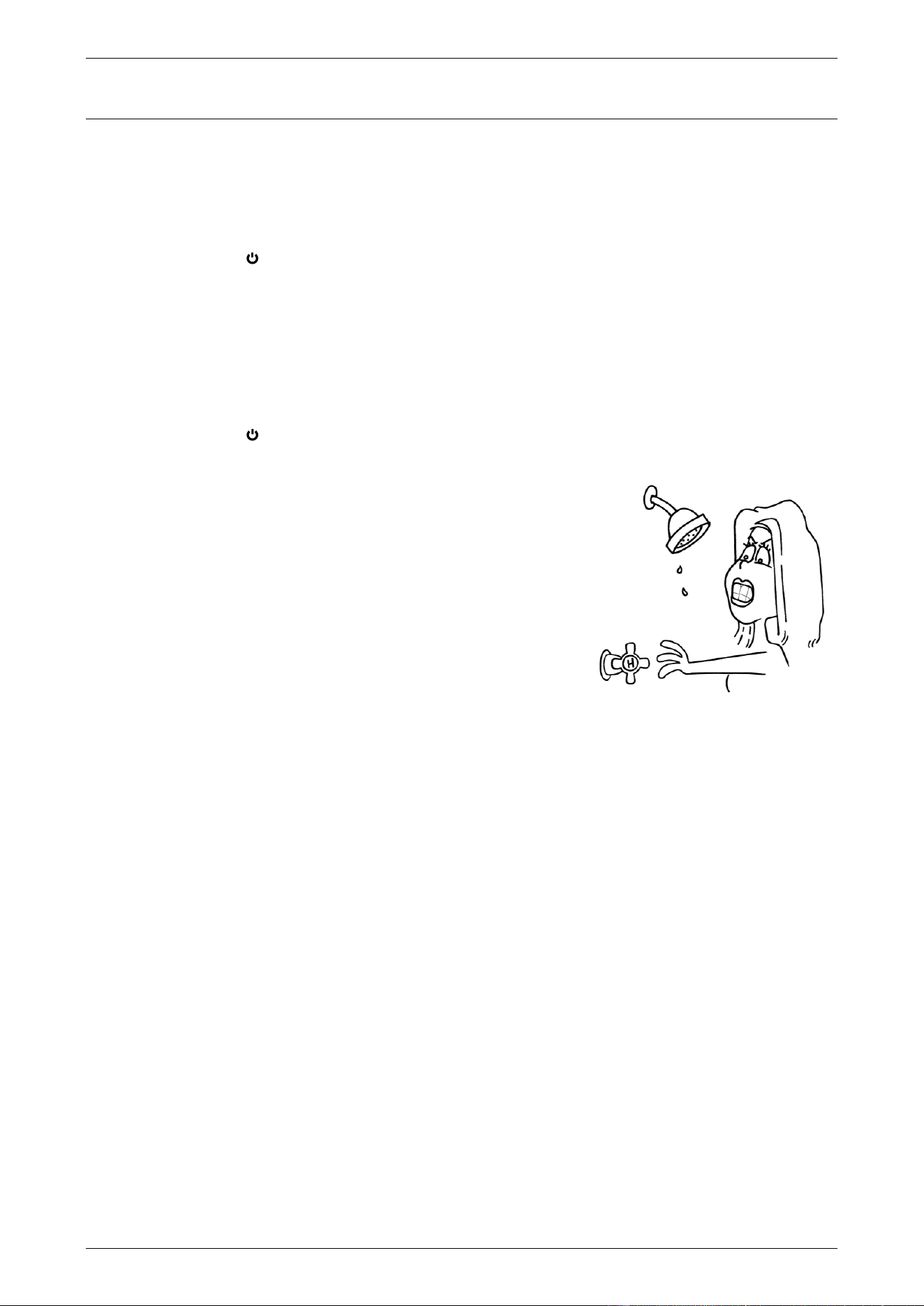
WATER IS TOO HOT OR NOT HOT ENOUGH
• Does the controller you are using have priority?
Refer to “Temperature Control” in the Owner’s Guide and Installation Instructions of the controllers.
Note: For an 866 series water heater, 50°C is the maximum available temperature setting.
NO WATER FROM THE HOT TAP
No flow of water from the hot tap may indicate a restriction in or failure of the cold water supply to the water
heater. Check for water flow at other taps and that the cold water isolation valve (refer to page 31) is fully open.
WATER FLOW FLUCTUATES
Too many taps in use at the same time may cause a decrease in the hot water flow from the taps. This can
also be evident if the water heater has been installed as an in-series gas booster to a solar water heater and
the solar heated water is at a low temperature.
• Are there several hot taps open, or are appliances such as a dishwasher or washing machine, in use at
the same time?
Ensure no more than two or three taps or appliances are on at the one time.
• Check the flow of hot water from each tap to see if one or more outlets are using more water than you
think.
Have a plumber install a flow control valve to each shower outlet, basin and sink to reduce water usage.
in use
priority
X 10L
88
°C
in use
priority
X 10L
88
°C

SAVE A SERVICE CALL
18
REDUCED HOT WATER FLOW WHEN HEAT EXCHANGER IS COLD
At a cold start-up, i.e. when the water heater has not operated for some time (which is most often first thing in
the morning), the initial flow of hot water may be reduced for a period of 5-10 seconds while the heat exchanger
warms up. This is both an energy and water saving feature of this water heater. Once the heat exchanger
has warmed up the hot water flow will increase and remain at normal flow levels. This feature will only occur
at a cold start-up and not when the heat exchanger is already warm from a recent use of hot water.
GAS BOOSTER OPERATING TOO FREQUENTLY
If the water heater is installed as an in-series gas booster to a solar water heater, you may find that the water
heater operates more frequently than expected. This will occur when the solar heated water temperature is
lower than 58°C, which may be experienced during periods of low solar energy gain or if there has been heavy
hot water usage. Factors to consider are:
• Hot tap not used recently
If a hot tap has not been used for a while, the water in the pipe work between the solar storage tank and
the in-series gas booster may have cooled down. The in-series gas booster will sense the cooler water
and this will cause the burners on the water heater to ignite and boost the water temperature when a hot
tap is first turned on. The burners will extinguish when solar preheated water of 58°C or higher from the
solar storage tank reaches the in-series gas booster (refer also to “Fan Continues to Run after Water
Heater Operation Stops” on page 18).
• Insufficient sunlight
Insufficient sunlight due to cloudy weather during hotter months or low solar energy contribution in colder
months may mean the in-series gas booster operates more often.
• Collectors shaded
If trees or other objects shade the solar collectors or if the glass is dirty, the effectiveness of the solar
collectors will be greatly reduced. Have the trees trimmed or the solar collectors relocated if the obstruction
is permanent or clean the collector glass.
Ensure the glass on your solar collectors is free of dust, salt spray or any other matter, which may reduce
the effectiveness of the solar collectors. If the collector glass becomes dirty, hose down or if the solar
collectors are accessible, wash the collector glass with water and a soft brush when the solar collectors
are cool.
• Collector area is too small
For most installations, the number of solar collectors recommended in Rheem literature has been proven
to provide the required solar energy to meet the average family needs. However, in some circumstances,
it may be necessary to install an additional solar collector.
• Are you using more hot water than you think?
Is one outlet (especially the shower) using more hot water than you think?
Very often it is not realised the amount of hot water used, particularly when showering. Carefully review
the family’s hot water usage. As you have installed an energy saving appliance, energy saving should
also be practised in the home. Adjust your water usage pattern to take advantage of maximum solar gains.
Have a plumber install a flow control valve to each shower outlet, basin and sink to reduce water usage.
• Water heater size
Do you have the correct size water heater for your requirements?
The sizing guide in the sales literature and on the Rheem website (www.rheem.com.au) suggests average
sizes that may be needed.
FAN CONTINUES TO RUN AFTER WATER HEATER OPERATION STOPS
It is the normal operation of the water heater for the fan to continue running after heating of the water is finished.
The fan may run for up to six minutes after the burners extinguish, to prepare for the next ignition.
SMELL OF FLUE GASES
The flue system may incorporate a condensate drain and condensate trap. A condensate trap must be filled
with water to prevent the escape of flue gases. If the water has evaporated flue gases may escape.
Remove the clamp securing the hose of the condensate trap to the spigot on the flue outlet. Remove the hose
from the spigot and fill the condensate trap with water. Reconnect the hose to the spigot. Ensure the hose is
not kinked when reconnected.
SAVE A SERVICE CALL
19
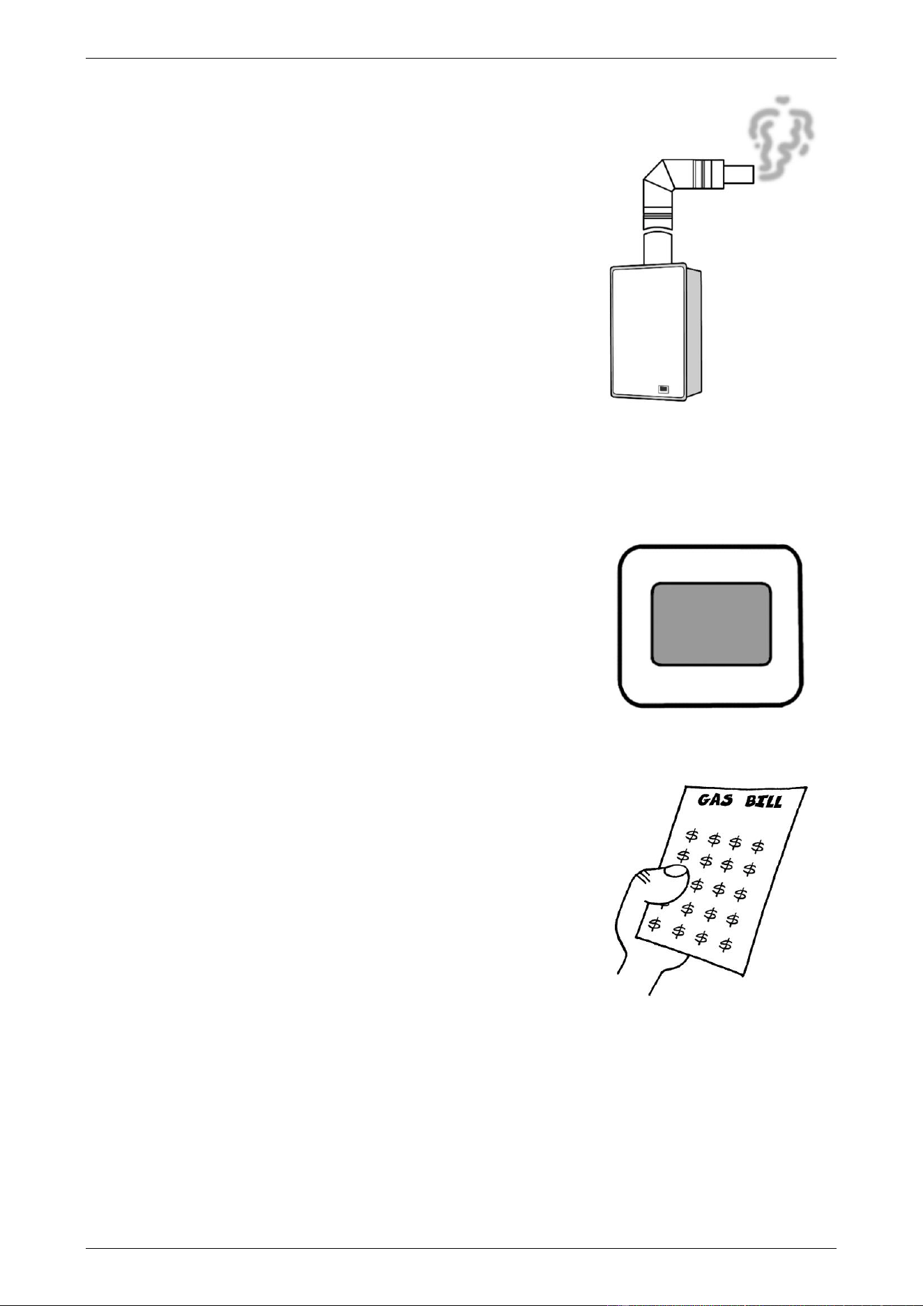
CLOUDS OF WHITE ‘VAPOUR’ FROM THE FLUE TERMINAL
During the heating cycle, it is not unusual to see water vapour clouds
steaming from the flue terminal, particularly on cold days. This is normal
operation of the water heater.
PRESSURE RELIEF VALVE DISCHARGING
A pressure relief valve is incorporated into the water heater controls.
This valve protects the water heater, by allowing water to escape, in the
event of excessive pressure build-up in the waterways.
• Normal operation
A small volume of water may discharge from the bottom of the water
heater when a hot tap is suddenly closed.
• Continuous dribble
A continuous dribble may indicate the water supply pressure is
above the design pressure for the water heater. If so, a pressure
limiting valve must be installed on the cold water supply pipe to the
water heater (refer to “Mains Water Supply” on page 22).
ERROR CODE
The water heater provides a diagnostic error code in the event of an interruption to its operation. The error
code is displayed on the controller(s) (if installed) and on the LED display on the front of the water heater as a
numerical value. If an error code appears:
• Close the hot tap, turn off the controller(s) and switch off the
electrical supply to the water heater.
• Check the gas isolation valve at the gas inlet to the water heater is
fully open.
• Wait 5 minutes, then switch on the electrical supply to the water
heater, turn on a controller and open a hot tap.
If the error code persists, take note of the numerical code, turn off the
hot tap and turn off the controller(s). Phone Rheem Service or their
nearest Accredited Service Agent to arrange for inspection.
HIGHER THAN EXPECTED GAS BILLS
Should you at any time, feel your gas bill is too high, we suggest you
check the following points:
• Is one outlet (especially the shower) using more hot water than you
think?
Carefully review the family’s hot water usage. Inexpensive flow
control valves can be easily fitted to the shower outlets to reduce
water usage.
• Is the in-series gas booster operating too frequently?
Refer to “Gas Booster Operating Too Frequently” on page 18.
• Has there been an increase in hot water usage?
An increase in hot water usage will result in an increase in water heater operation.
• Has your water heating tariff rate been increased by your gas retailer since your previous bill?
IF YOU HAVE CHECKED ALL THE FOREGOING AND STILL BELIEVE YOU NEED ASSISTANCE, PHONE
RHEEM SERVICE OR THEIR NEAREST ACCREDITED SERVICE AGENT.
20
INSTALLATION – WATER HEATER
THIS WATER HEATER IS FOR INDOOR INSTALLATION ONLY.
THIS WATER HEATER IS NOT SUITABLE FOR POOL HEATING.
Check the water heater is suitable for the gas type available.
(refer to the rating label on the water heater)
INSTALLATION STANDARDS
The water heater must be installed:
• by a qualified person, and
• in accordance with the installation instructions, and
• in compliance with the Plumbing Code of Australia (PCA), Standards AS/NZS 3500.4 and
AS/NZS 5601.1, and all local codes and regulatory authority requirements.
864 series
Warning: This water heater may deliver water at high temperature. Refer to the Plumbing Code of
Australia, local requirements and these installation instructions to determine if additional delivery temperature
control is required. Refer to “Hot Water Delivery” on page 23.
866 series
This water heater delivers water not exceeding 50°C in accordance with AS 3498.
Warning: This water heater must only be installed in accordance with the acceptable plumbing
configurations specified in these installation instructions. Failure to do so may result in conditions where
delivery temperature control is inadequate. Refer to “Water Temperature Diagrams” on page 28.
All packaging materials must be removed from the water heater prior to its installation.
WATER HEATER APPLICATION
This water heater is designed for use in a single family domestic dwelling for the purpose of heating potable
water. Its use in an application other than this may shorten its life.
If this water heater is to be used where an uninterrupted hot water supply is necessary for the application or
business, then there should be back-up redundancy within the hot water system design. This should ensure
the continuity of hot water supply in the event that this water heater was to become inoperable for any reason.
We recommend you provide advice to the system owner about their needs and building back-up redundancy
into the hot water supply system.
The 864 series of water heater may be installed as an in-series gas booster to a solar water heater. For
information relating to the function and operation of the solar water heater, refer to the Owner’s Guide and
Installation Instructions supplied with the solar water heater.
Note: Australian Standard AS 3498 requires that a water heater provides the means to inhibit the growth of
Legionella bacteria in potable water. When the 864 series water heater is used as an in-series booster for a
solar water heater it can satisfy the AS 3498 requirements provided it is energised, the booster preset outlet
temperature setting is at least 70°C, and that a remote temperature controller is not used.
Note: The 866 series of water heater is marked “THIS APPLIANCE DELIVERS WATER NOT EXCEEDING
50°C IN ACCORDANCE WITH AS 3498” on the front panel. This model;
• must not be installed as an in-series gas booster to a solar water heater, as water temperature greater
than 50°C can be delivered from the water heater contravening its compliance to AS 3498.
INSTALLATION – WATER HEATER
21
WATER HEATER LOCATION
The water heater is suitable for indoor installation only and should be installed close to the most frequently
used outlet and its position chosen with safety and service in mind. If this water heater is part of a solar water
heater system, it should also be installed close to the solar storage tank. Make sure people (particularly
children) will not touch the flue outlet. The flue outlet and air inlet must be clear of obstructions.
Clearance must be allowed for servicing of the water heater.
The water heater must be accessible without the use of a
ladder or scaffold. Make sure the entire front panel can be
removed for service. You must be able to read the
information on the rating plate. Remember you may have to
take the entire water heater out later for servicing.
There are also special requirements in AS/NZS 5601.1 for
water heaters installed in a garage, an enclosed space and
other locations. Remember all local authorities have
regulations about putting water heaters into roof spaces.
This water heater must be installed vertically upright with the
water, gas and power connections on the underside,
pointing toward the floor. The back of the water heater can
be either against a wall or supported by a frame. A heat
shield or insulating material or an air gap is not required
between the back of the water heater and the wall or frame
to comply with the temperature limitation requirement of
AS/NZS 5601.1.
Note: The water heater must be well secured to the wall or frame using two fasteners each at the top and
bottom of the unit (refer to page 29 for mounting hole positions and weight of the water heater). Use the screws
provided only if they are suitable for the wall or frame type. Otherwise select and use alternative fasteners
suitable for the application. The fasteners must be capable of bearing the full weight of the water heater so it
may not work loose nor impose any load on the gas and water pipe work connected to the water heater. Refer
to the fastener manufacturer’s information and recommendations for the type of fastener to use for the wall or
frame type and load bearing requirements.
For a single water heater installation, refer to the typical installation diagram on page 30.
For a dual water heater installation using the EZ Link system, refer to “EZ Link System Dual Installation” on
page 52 and the typical installation diagram on page 56.
The water heater must not be installed in an area with a corrosive atmosphere where chemicals are stored or
where aerosol propellants are released. Remember the air may be safe to breathe, but when it goes through
a flame, chemical changes take place which may attack the water heater.
VENTILATION
This water heater is to be installed with a Rheem coaxial flue system. The kit enables a room sealed
installation, drawing air for combustion from outside of the building.
The ventilation of a room or an enclosure such as a cupboard, where the water heater is installed must comply
with the requirements of AS/NZS 5601.1.
SECONDARY FLUE
A secondary flue must be installed with an indoor water heater to discharge combustion products to outside
the building. The water heater MUST ONLY be installed with a certified Rheem coaxial flue system.
Where more than one water heater is installed, each water heater must be individually flued using a certified
Rheem coaxial flue system. A common flue system MUST NOT be used.
Refer to “Flueing” on page 33 for details on the flue requirements and installation details.
INSTALLATION – WATER HEATER
22
FROST PROTECTION
The water heater has a frost protection system. The frost protection system will protect the water heater from
damage, by preventing ice forming in the waterways of the water heater, in the event of freezing conditions
occurring.
The frost protection system will be rendered inoperable if electrical power is not available at the water heater.
Damage to the water heater caused by freezing of the pipe work to or from the water heater is not covered
under the Rheem warranty. Refer to AS/NZS 3500.4 for precautions to be taken for installations in frost prone
areas. The water heater is not suitable for installation in areas where the ambient temperature falls below -
20°C (including wind chill factor).
The cold water line to the water heater must be insulated with suitable thickness insulation if freezing conditions
are likely to occur. The insulation must be fitted to the underside of the water heater and be weatherproof and
UV resistant if exposed.
MAINS WATER SUPPLY
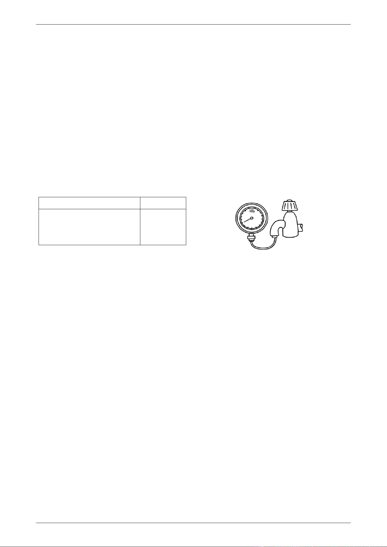
Where the mains water supply pressure exceeds that shown in the table below, an approved pressure limiting
valve that does not have non-return valve characteristics (such as an RMC PSL series valve) is required and
should be fitted as shown in the water and gas connection detail diagram on page 31.
Model
B28
Relief valve setting
1750 kPa
Maximum mains supply pressure
1000 kPa
Minimum mains supply pressure *
120 kPa
* minimum water supply pressure required to achieve the
rated flow and performance
Notes
• It is not recommended to install this water heater with a low pressure water supply.
• A minimum water supply pressure of 120 kPa is required to achieve the rated flow and performance of
the water heater.
• If this water heater is installed as an in-series gas booster for a solar water heater, the maximum water
supply pressure to the solar water heater, without an expansion control valve (ECV), is generally 800 kPa,
however it may be less than this for some models. Refer to the Owner’s Guide and Installation Instructions
supplied with the solar water heater for maximum mains supply pressure details.
• If sludge or foreign matter is present in the water supply, it is recommended a suitable filter be incorporated
in the cold water line to the water heater.
• This water heater is not suitable for connection to bore water or spring water unless a water treatment
device is fitted.
• Refer to “Water Supplies” on page 16 for further information on water chemistry.
INSTALLATION – WATER HEATER
23
HOT WATER DELIVERY
Warning: This water heater can deliver water at temperatures which can cause scalding.
866 series – 50°C Limited Outlet
An 866 series water heater delivers water not exceeding 50°C in accordance with AS 3498. The risk of scald
injury will be reduced.
There is no need to fit a temperature limiting device to satisfy the requirements of the Plumbing Code of
Australia, if an 866 series water heater is installed and serving an application where 50°C is the maximum
permissible hot water temperature at the outlet of a fixture or appliance used primarily for personal hygiene,
such as in a bathroom or ensuite.
864 series – Hot Water Outlet
Depending upon its preset outlet temperature setting, an 864 series water heater can deliver hot water at a
temperature up to 75°C when no temperature controller is installed and 60°C when a temperature controller is
installed. These temperatures are sufficiently hot to cause severe scalding. A model used as a booster to a
solar water heater can deliver hot water exceeding these temperatures. Water at these temperatures may be
plumbed to fixtures where water hotter than 50°C is allowed, such as the kitchen and laundry.
The installing plumber may have a legal obligation to ensure the installation of this water heater meets the
water temperature delivery requirements of the Plumbing Code of Australia so that heated water delivered to
fixtures and appliances used primarily for personal hygiene is at a temperature which is unlikely to scald.
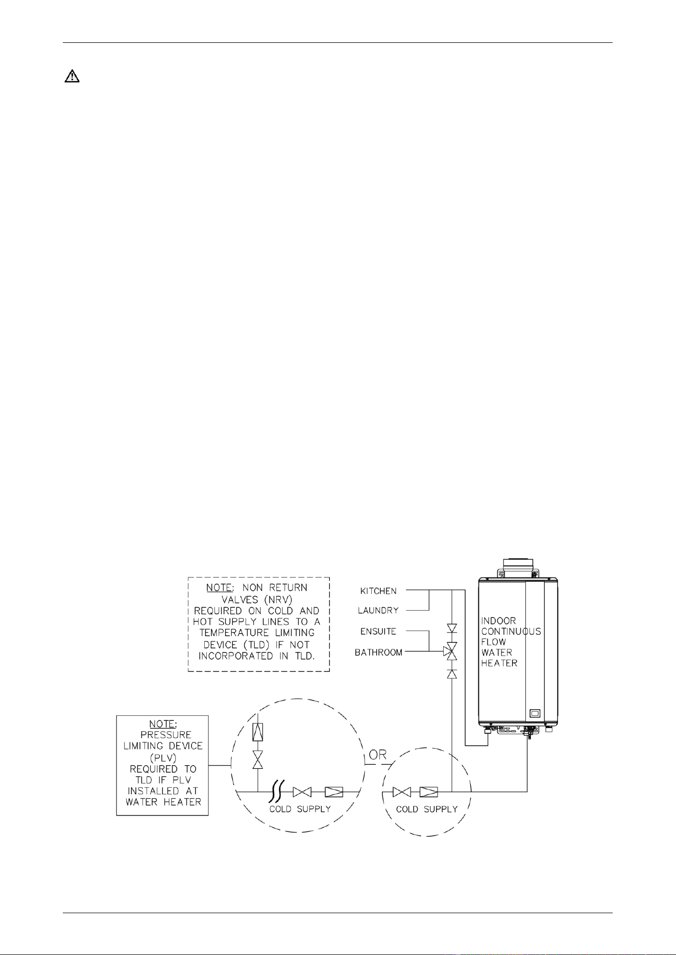
It is necessary and we recommend that a temperature limiting device be fitted between an 864 series water
heater and the fixtures and appliances used primarily for personal hygiene such as in a bathroom, ensuite,
public amenities or other ablution areas, to reduce the risk of scalding. The temperature limiting device must
be of a type suitable for use with a gas continuous flow water heater. Refer to the manufacturer’s specifications
of the temperature limiting device.
Where a temperature limiting device is installed adjacent to the water heater, the cold water line to the
temperature limiting device can be branched off the cold water line either before or after the isolation valve
and pressure limiting valve to the water heater.
If a pressure limiting valve is installed on the cold water line to the water heater and the cold water line to a
temperature limiting device branches off before this valve or from another cold water line in the premises, then
a pressure limiting valve of an equal pressure setting may be required prior to the temperature limiting device.
Two Temperature Zones Using a Temperature Limiting Device
INSTALLATION – WATER HEATER
24
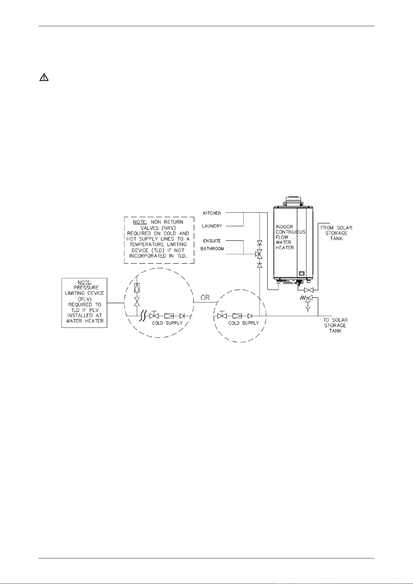
Gas Booster for a Solar Water Heater
The temperature limiting device used with an 864 series in-series gas booster as part of a solar water heater
installation must be of a type suitable for use with both a continuous flow water heater and a solar water heater.
Refer to the manufacturer’s specifications of the temperature limiting device.
Warning: Temperature controllers must not be fitted to this water heater (864 series) if it is installed as
an in-series gas booster with a solar water heater system because water at a temperature much higher than
the controller setting can be delivered. If a solar water heater has been installed to an existing water heater
installation, then all controllers must be disconnected and removed.
Where a temperature limiting device is installed adjacent to the in-series gas booster, the cold water line to the
temperature limiting device can be branched off from either the cold water line to the solar storage tank or
another cold water line in the premises. It must not be branched off the water line from the solar storage tank.
If a pressure limiting valve is installed on the cold water line to the solar water heater and the cold water line
to a temperature limiting device branches off before this valve or from another cold water line in the premises,
then a pressure limiting valve of an equal pressure setting may be required prior to the temperature limiting
device.
In-series Gas Booster as part of a Typical Solar Water Heater Installation
Two Temperature Zones Using a Temperature Limiting Device
Note: Refer to the installation instructions supplied with the solar storage tank for further information on the
location of a cold water branch line to a temperature limiting device relative to the installation of the cold water
valves in the cold supply pipework prior to the solar storage tank.
INSTALLATION – WATER HEATER
25
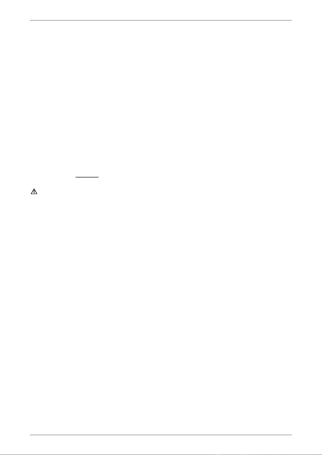
CIRCULATED HOT WATER FLOW AND RETURN SYSTEM
A Rheem 864B28 model continuous flow water heater can be installed as part of a circulated hot water flow
and return system in a building.
Notes
• the preset outlet temperature setting of the water heater must be set to at least 60°C.
• the return water temperature to the water heater must not be less than 55°C.
If the water temperature decreases by more than 5°C due to heat loss from the ring main, the preset outlet
temperature setting of the water heater must be set to above 60°C to ensure the return water temperature
is not less than 55°C.
• temperature controllers should not be installed with a water heater as part of a circulated hot water flow
and return system, including when installed as part of an EZ Link System dual installation.
The circulator must be:
• sized and set to provide a minimum flow rate of 3.0 L/min through the recirculated hot water flow and
return system, and
• either thermostatically and / or timer controlled.
The circulator must not be set to operate continuously, i.e. 24 hours per day.
Warning: A Rheem 866 series continuous flow water heater must not be installed as part of a circulated
hot water flow and return system in a building.
Temperature Limiting Device
A temperature limiting device cannot be installed in circulated hot water flow and return pipe work. The
tempered water from a temperature limiting device cannot be circulated. Where a circulated hot water flow and
return system is required in a building, a temperature limiting device can only be installed on a dead leg,
branching off the circulated hot water flow and return pipe.
If circulated tempered water were to be returned back to the water heater, depending on the location of the
return line connection on the water supply line to the water heater, then either:
• water will be supplied to the cold water inlet of the temperature limiting device at a temperature exceeding
the maximum recommended water supply temperature, or
• when the hot taps are closed no water will be supplied to the cold water inlet of the temperature limiting
device whilst hot water will continue to be supplied to the hot water inlet of the temperature limiting device.
These conditions may result in either water at a temperature exceeding the requirements of AS/NZS 3500.4
being delivered to the hot water outlets in the ablution areas, or the device closing completely and not delivering
water at all, or the device failing. Under either condition, the operation and performance of the device cannot
be guaranteed.
INSTALLATION – WATER HEATER
26
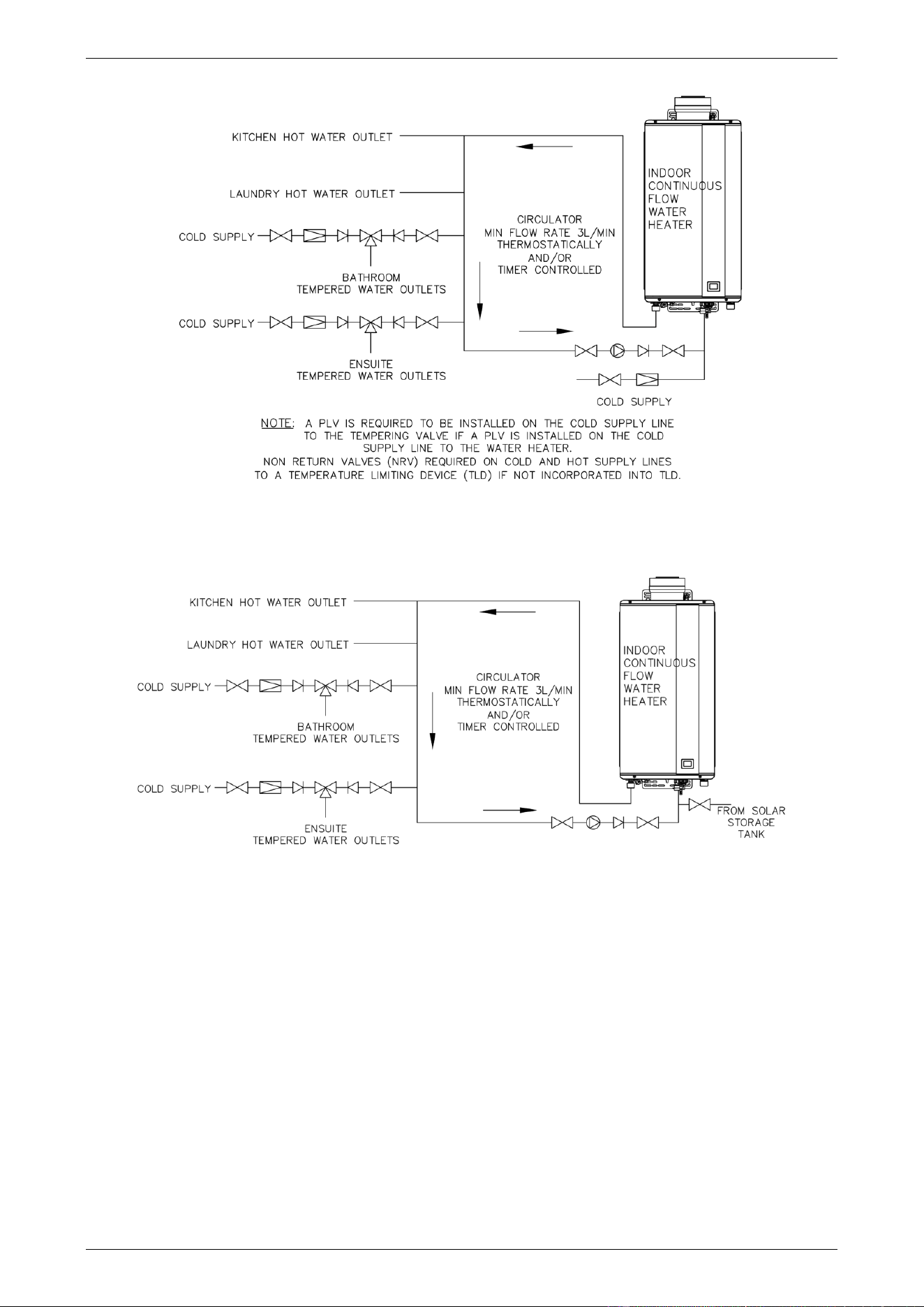
Circulated Hot Water Flow and Return
Gas Continuous Flow Water Heater
Circulated Hot Water Flow and Return
In-series Gas Booster as part of a Solar Water Heater Installation

INSTALLATION – WATER HEATER
27
TEMPERATURE CONTROLLERS
The Rheem 864 and 866 series can be installed with Rheem Standard controllers to enable the user to control
the temperature of the delivered water from the outlet of the water heater.
There are three types of Standard controller. They are the Kitchen controller, Bathroom 1 controller and the
Bathroom 2 controller. The controllers are designed to be hard wired into the water heater using either the
Kitchen controller cable or the Bathroom controller cable.
Temperature controllers are only suitable for either a single water heater installation or a dual water heater
installation using the EZ Link system. They are not suitable if multiple water heaters are manifolded together.
Other manufacturers’ controllers are not suitable to and cannot be installed with this water heater.
Warning: Temperature controllers must not be fitted to this water heater (864 series) if it is installed as an
in-series gas booster with a solar water heater system because water at a temperature much higher than the
controller setting can be delivered. If a solar water heater is installed to an existing water heater installation,
then all controllers must be disconnected and removed.
Refer to the Rheem website for the Owner’s Guide and Installation Instructions for the Standard Rheem
Controllers. Visit www.rheem.com.au/rheem/help#guides.
EZ LINK DUAL INSTALLATION
Two 864B28 or 866B28 gas continuous flow water heaters can be installed as an EZ Link dual installation.
The EZ Link
®
system is designed to electronically control the two gas continuous flow water heaters and have
them operate as one. One or both water heaters may be in operation, depending upon the hot water demand.
The second water heater will only operate when the hot water demand exceeds the capacity of the first water
heater to supply.
Refer to “EZ Link System Dual Installation” on page 52.
REDUCING HEAT LOSSES
The hot water line from the water heater and the pipe work between the solar storage tank, if one is installed,
and the in-series gas booster must be insulated in accordance with the requirements of AS/NZS 3500.4. The
insulation must be weatherproof and UV resistant if exposed. The insulation must be fitted up to the
connections on the both the underside of the water heater and the solar storage tank.
INSTALLATION – WATER HEATER
28
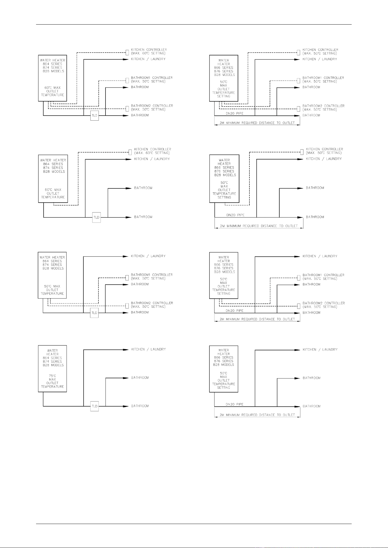
WATER TEMPERATURE DIAGRAMS
864 Series - Kitchen and Bathroom Controllers 866 Series – Kitchen and Bathroom Controllers
864 Series - Kitchen Controller Only 866 Series - Kitchen Controller Only
864 Series - Bathroom Controllers Only 866 Series - Bathroom Controllers Only
864 Series - No Controllers 866 Series - No Controllers
Notes
• Temperature Limiting Devices – refer to “Hot Water Delivery” on page 23.
• Factory preset outlet temperature setting is:
◼ 864 series 60°C 866 series 50°C
INSTALLATION – WATER HEATER
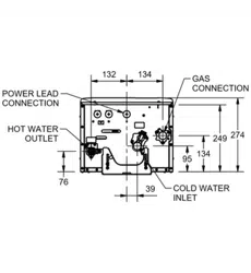
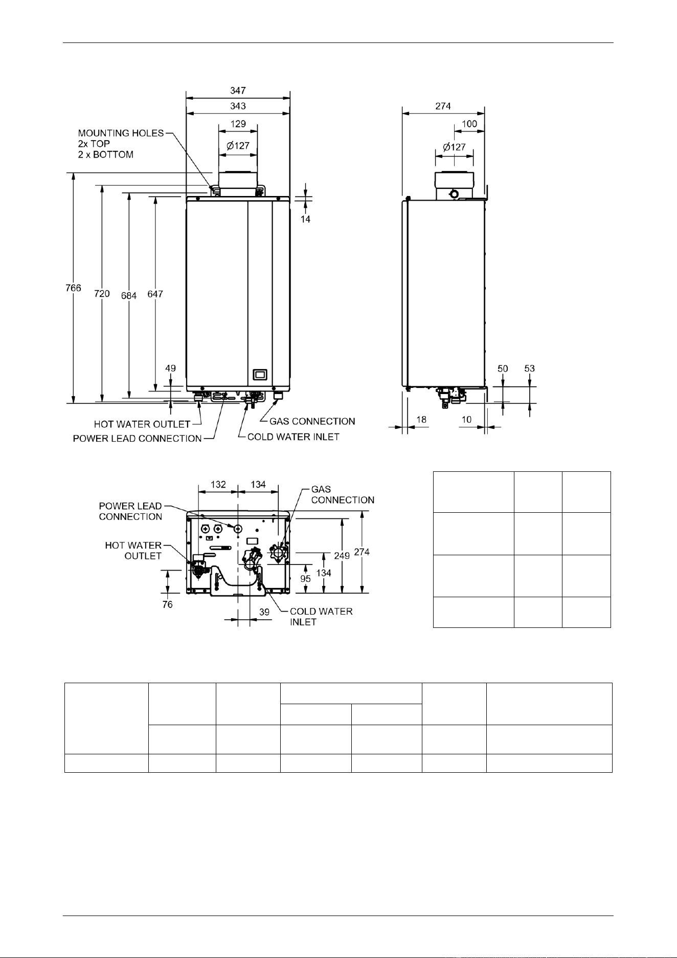
29
DIMENSIONS AND TECHNICAL DATA
Gas Details
Hourly Gas
Consumption
(MJ)
Min Gas
Pressure
(kPa)
Test Point Gas Pressure (kPa)
Max Gas
Pressure
(kPa)
Injector Size (mm)
minimum
maximum
Model
864B28
866B28
864B28
866B28
864B28
866B28
864B28
866B28
864B28
866B28
864B28
866B28
Natural Gas
210
1.13
0.175
0.720
3.50
19 x 1.73 & 19 x 1.25
Model Numbers
• Gas type Letter N is included in the model number to denote gas type.
N = Natural – E.g. 864B28NF, 866B28NF
• Frost protection Letter F is included in the model number to denote frost protection.
Model
864B28
866B28
Natural
Water heating
capacity
@ 40°C rise
litres / min
17.5
Nominal
capacity
@ 25°C rise
litres / min
28
Mass Empty
(unpackaged)
kg
27
Technical data is subject to change.
INSTALLATION – WATER HEATER
30
TYPICAL INSTALLATION – INDOOR LOCATION
31
CONNECTIONS – PLUMBING
All plumbing work must be carried out by a qualified person and in compliance with the Standard
AS/NZS 3500.4 and all local codes and regulatory authority requirements.
All gas work must be carried out by a qualified person and in compliance with the Standard AS/NZS 5601.1,
all local codes and regulatory authority requirements.
CONNECTION SIZES
Model
864B28
866B28
Hot water outlet connection
R 3/4
-
50°C limited outlet connection
-
R 3/4
Cold water inlet connection
R 3/4
R 3/4
Gas inlet connection
R 3/4
R 3/4
WATER INLET AND OUTLET
All pipe work must be cleared of foreign matter before
connection and purged before attempting to operate the
water heater. All olive compression fittings must use brass
or copper olives. Use an approved thread sealant such as
Teflon tape on all threaded joints. Only use sufficient thread
sealant to seal a joint. Refer to the sealant manufacturer’s
guidelines for how much and where to use.
Warning: Sealant must not be allowed in the waterways
of pipe work or fittings. Excess sealant may be carried into
the water heater where it will damage components and
block the internal filters. This damage to components or
blockage of filters is not covered by the Rheem warranty
and a service rectification fee will be charged.
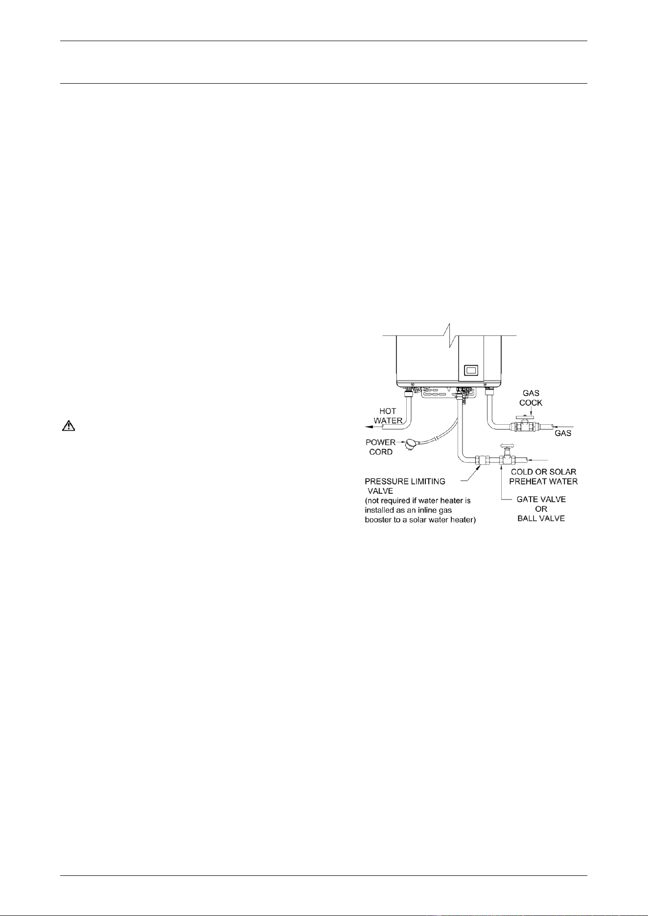
A full flow gate valve or ball valve must be installed on the
cold water line to the water heater. A non-return valve or
stop tap must not be installed. An acceptable
arrangement is shown in the diagram. Refer also to “Hot
Water Delivery” on page 23 and to “Mains Water Supply” on
page 22.
A disconnection union must always be provided at the cold water inlet and hot water outlet on the water heater
to allow for disconnection of the water heater.
Insulation used on the cold and hot water lines must extend up to the cold water inlet and hot water outlet of
the water heater.
This water heater is intended to be permanently connected to the water mains and not connected by a hose-
set. A braided flexible hose or semi-flexible connector may be used for connection to the water heater, where
permitted by AS/NZS 3500.4.
Notes
• It is essential all pipe connections be correctly aligned, otherwise component connections within the water
heater may be strained and / or components themselves misaligned. It is recommended also, wherever
possible, pipe connections be made at the water heater first and final pipe runs be made in soft copper
pipe to allow some adjustment for misalignment.
• Use the spanner flats on the water heater fittings and take care to avoid twisting the water inlet and outlet
pipes inside the jacket.
Gas Water Heater
Cold (or Solar Preheat) and Hot Water
and Gas Connection Details
CONNECTIONS – PLUMBING
32
PIPE SIZES
The pipe sizing for hot water supply systems should be carried out by persons competent to do so, choosing
the most suitable pipe size to ensure adequate flow for each individual application. Reference to the technical
specifications of the water heater and local regulatory authority requirements must be made.
To achieve true mains pressure operation, the cold water line to the water heater should be the same size or
bigger than the hot water line from the water heater.
The minimum recommended cold pipe or solar preheat pipe and hot pipe size is DN20.
IN-SERIES BOOSTER
The pipe work between the solar storage tank (if one is installed) and the in-series gas booster has a minimum
recommended pipe size of DN20 and MUST BE of copper unless an insulated braided flexible hose is provided
with a solar water heater connections kit for this purpose.
The pipe work shall be fully insulated with a closed cell type insulation or equivalent in accordance with the
requirements of AS/NZS 3500.4. The insulation must be weatherproof and UV resistant if exposed. The
insulation must be fitted up to the connections on both the solar storage tank and the in-series gas booster.
A full flow isolation valve may be installed on the solar preheat water line from a solar storage tank to the in-
series gas booster.
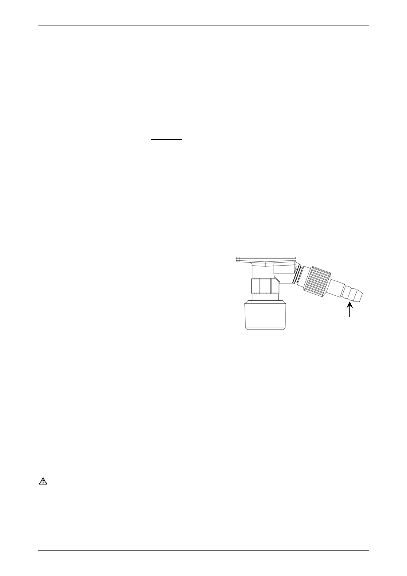
RELIEF VALVE DRAIN
A pressure relief valve is incorporated into the hot water outlet fitting of the water heater. A drain line is
recommended to be fitted to the relief valve to carry any discharge clear of the water heater.
A one (1) metre length of flexible silicone tubing is supplied
with the water heater to use as a drain line for the relief valve.
The tubing is to be cut to length to suit the distance from the
water heater to the drain line discharge point.
Connect the drain line to the relief valve using a suitable
restraining device such as a hose clamp or pipe clamp. The
drain line from the valve to the point of discharge should be as
short as possible, have a continuous fall all the way from the
water heater to the discharge outlet and have no restrictions,
twists or kinks in the tubing. Pipe clips are to be used to secure
the drain line to a wall at a suitable spacing so the drain line
will not sag over time. The pipe clips are to be installed so not
to cause a restriction or compress, pinch or distort the tubing.
The outlet of a drain line must be in such a position that flow out of the pipe can be easily seen, but arranged
so discharge will not cause damage or nuisance or result in injury, such as a slip injury. The termination point
of a drain line must comply with the requirements of AS/NZS 3500.4.
GAS INLET
The gas connection is made at the underside of the water heater. The pipe work must be cleared of foreign
matter before connection and purged before attempting to operate the water heater. An isolation valve and
disconnection union must be installed to allow servicing and removal of the water heater (refer to the diagram
on page 31).
Note: Refer to the Gas Installations Standard AS/NZS 5601.1 for the correct method of sizing the gas supply
pipe to the water heater. The pipe size selection must take into account the high gas input of this water heater
(refer to table on page 29) as well as all of the other gas appliances in the premises.
Warning: Always isolate the water heater before pressure testing the gas supply system. Disconnect the
water heater after the isolation valve to prevent the risk of serious damage to the gas control. The Rheem
warranty does not cover damage of any nature resulting from failure to observe this precaution. Refer to rating
label for gas types and pressures.
Hot Water Outlet Fitting
pressure relief
valve and
drain outlet
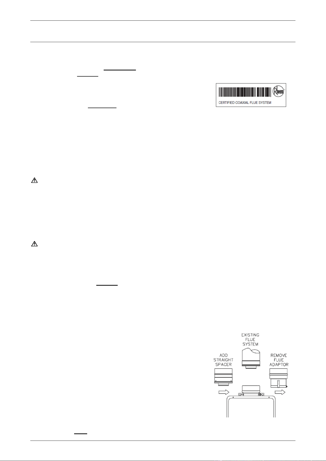
33
FLUEING
SECONDARY FLUE
A secondary flue must be installed with an indoor water heater to discharge combustion products to outside
the building. The water heater MUST ONLY be installed with certified Rheem coaxial flue components carrying
the label opposite. DO NOT use any other type of flue parts.
Where more than one water heater is installed, each water heater must
be individually flued using certified Rheem coaxial flue components.
A common flue system MUST NOT be used.
The installation of the secondary flue must be carried out by a qualified person and be in accordance with the
Gas Installations Standard AS/NZS 5601.1, local authority requirements and the installation instructions. A
charge will be made for any service related call due to the installation of the flue system not complying with
these installation instructions.
The water heater must be flued separately from all other appliances and flued to the outdoors. Minimum
clearance requirements apply from the flue terminal in accordance with AS/NZS 5601.1 (refer also to “Flue
Terminal Location” on page 35). Do not install the flue to discharge into a chimney. There is no requirement
on the flue to maintain a minimum distance from combustible materials.
Warning: Where the flue penetrates through walls, floors or ceilings, the penetration must comply with
local regulations for fire rating. The coaxial flue system does not have nor provides a fire rating.
The water heater flue may only be terminated with a Horizontal Flue Terminal at the end of either a horizontal
or vertical flue. The secondary flue must be self-supporting and not impose a load on the water heater. Flue
runs must be adequately supported along both horizontal and vertical runs. The maximum recommended
unsupported span for a horizontal run is no more than 2.0 m. Support isolation hanging bands should be used.
Do not use wire. Wall Brackets (PN 295129) are available and should be used for vertical runs. The coaxial
flue components are to be connected together using the screws provided. The flue outside diameter is 127 mm.
Warning: Never operate the water heater unless it has been installed in accordance with the installation
instructions. Failure to install the water heater in accordance with the installation instructions, properly flueing
the water heater to the outdoors and ensuring it has an adequate air supply, will result in unsafe operation of
the water heater, possibly causing fire, explosion, serious injury and asphyxiation from carbon monoxide.
A sealing gasket is located at one end of the inner flue. Check all flue components to ensure the gasket is in
place and properly seated. DO NOT install if any gaskets are missing. Contact Rheem Service or their nearest
Accredited Service Agent if the gasket is missing.
REPLACING AN 864, 866 027 OR 627 MODEL WITH AN 864, 866B28 MODEL
An 864, 866B28 model is taller than the superseded 864, 866027 model. If a new B28 model is replacing the
superseded model, the original Flue Adaptor connected to the 864, 866027 model needs to be removed and
a Straight Spacer (PN 295140) installed on the 864, 866B28 model.
1. Loosen the ring clamp on the Flue Adaptor and undo the screws
securing this component to the flue above.
2. Disconnect and remove the 864, 866027 model water heater and
the Flue Adaptor.
3. Fit the Straight Spacer to the 864, 866B28 model water heater prior
to securing the water heater on the wall.
4. Locate the Straight Spacer into the existing flue system and secure
the water heater to the wall.
5. Secure the Straight Spacer to the adjacent flue component with the
screws provided.
6. Where an existing Condensate Trap and drain line is installed, this
is to remain connected to its existing flue fitting. The condensate
connection at the top of the 864, 866B28 model is not used and the
blanking cap must remain in place.
Remove Flue Adaptor –
Install Straight Spacer
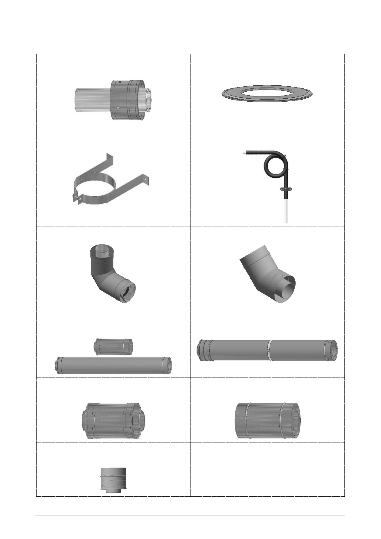
FLUEING
34
COMPONENTS
A complete flue system is comprised from the following components.
horizontal flue terminal
(PN 295146)
trim ring
(PN 295125)
wall bracket
(PN 295129)
condensate trap
(PN 295139)
90° elbow
(PN 295147)
45° elbow
(PN 295148)
flue extensions
(PN 295152) – 300 mm
(PN 295149) – 900 mm
adjustable flue extension – 560 to 890 mm
(PN 295153)
male to male (MM) adaptor
(PN 295151)
female to female (FF) adaptor
(PN 295150)
straight spacer – 105 mm
(PN 295140) – (to convert flue from ‘027’ to ‘B28’ model)

FLUEING
35
FLUE TERMINAL LOCATION
The water heater must be located to ensure that the location of the flue terminal complies with the requirements
of AS/NZS 5601.1. As a guide the following requirements are extracted from the Gas Installations Standard.
The distances are measured along the wall from the flue penetration.
Horizontal Flue Terminal Location
• At least 300 mm between the top of the flue terminal and the eaves.
• At least 300 mm between the bottom of the flue terminal and the ground, balcony or other surface.
• At least 500 mm between the flue terminal and the edge of any opening into the building, such as an
openable door or window, measured horizontally*.
• At least 1500 mm between the top of the flue terminal and the edge of any opening into the building, such
as an openable window, measured vertically.
• At least 300 mm between the flue terminal and a return wall or external corner, measured horizontally*.
• At least 1500 mm between the flue terminal and any opening into a building, in the direction of the flue
discharge.
• At least 500 mm between the flue terminal and a fence, wall or other obstruction, in the direction of the
flue discharge.
• At least 450 mm between the flue terminal and a property boundary unobstructed by a fence, wall or other
obstruction, in the direction of the flue discharge.
• At least 300 mm between the flue terminal and any other flue terminal, cowl or other combustion air intake.
Note: * If these horizontal distances cannot be achieved, AS/NZS 5601.1 states an equivalent horizontal
distance measured diagonally from the nearest discharge point of the flue terminal to the opening may be
deemed to comply. Check with the local regulator.
For a multiple water heater installation, refer to “Multiple Flue Terminations through Wall” on page 47 for
minimum distances between flue terminals.
Vertical Flue Terminal Location
• At least 500 mm between the underside of the flue terminal and the nearest part of a non-trafficable roof.
• At least 2000 mm between the end of the flue terminal and the nearest part of a trafficable roof and
500 mm above any surrounding parapet. The flue is to be supported.
• At least 1500 mm between the top of the flue terminal and the edge of any opening into the building, such
as an openable window, measured vertically.
• At least 500 mm between the flue terminal and any building structure or obstruction facing the terminal,
measured horizontally.
• At least 1500 mm between the flue terminal and the edge of any opening into the building, measured
horizontally.
• At least 300 mm between the flue terminal and any other flue terminal, cowl or other combustion air intake.
• At least 200 mm between the flue terminal and the nearest part of a chimney.
For a multiple water heater installation, refer to “Multiple Flue Terminations through Roof” on page 47 for
minimum distances between flue terminals.
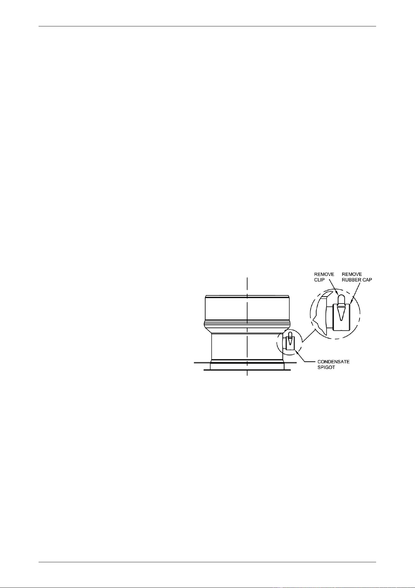
FLUEING
36
FLUE LENGTHS
Maximum Flue Length
The system will not operate if there is excessive restriction (pressure drop) in the flueing system.
The water heater is approved to have a maximum length of a secondary flue between the water heater and
the flue terminal of 9 m when the flue is installed with 3 x 90° Elbows or 6 x 45° Elbows. The maximum straight
flue length with no elbows is 13.5 m to the flue terminal.
• To determine the maximum length of flue to the flue terminal for an installation, reduce the maximum
straight flue length of 13.5 m:
▪ by 1.5 m for every 90° Elbow, and
▪ by 0.75 m for every 45° Elbow.
• A secondary flue may have a combination of 90° Elbows and 45° Elbows.
• Horizontal runs of flue must be installed with a gradient of 20 mm per metre of horizontal run. Refer to
“Draining the Condensate and Flue Gradient” on page 36 and “Horizontal Flue Runs” on page 38.
Note: Ensure the seam of the inner flue in horizontal runs is at the top of the installation.
Minimum Flue Length
The minimum horizontal flue distance which may be used is 300 mm, provided:
• one 90° Elbow is connected to the flue outlet of the water heater, and
• the Horizontal Flue Terminal is connected to the 90° Elbow.
FLUE CONDENSATE
Condensate from the combustion gases may
form in the flue. The flue outlet assembly at the
top of the water heater incorporates a
condensate drain spigot to allow for draining of
this condensate.
This spigot is covered by a rubber cap held in
position by a clamp. For certain types of
installations, it will be necessary to remove the
clamp and cap and install a Condensate Trap
(PN 295139) and drain line.
The Condensate Trap must be filled with water
prior to the operation of the water heater. Refer
to “Condensate Trap and Condensate Drain
Line” on page 37.
Draining the Condensate and Flue Gradient
A Condensate Trap and drain line must be installed under the following conditions in order to prevent
condensate from draining back into the water heater:
• Where vertical sections exceeding 2 m are incorporated in a flue that penetrates a wall and terminates.
• Where a flue penetrates the roof and terminates.
• Where there is a horizontal run of flue between two elbows and the elbow closest to the flue terminal is
orientated upward.
▪ This horizontal run of flue must have a gradient upward to the flue terminal. Condensate will drain
back toward the water heater.
Failure to install a Condensate Trap and drain line could allow acidic flue gas condensate to enter into the
water heater flue-way, causing premature failure of the water heater. Any resultant faults will not be covered
by the Rheem warranty.
Note: A horizontal run of flue connecting directly to a Horizontal Flue Terminal must have a gradient downward
to the flue terminal. Condensate will drain from the flue terminal.
condensate drain spigot
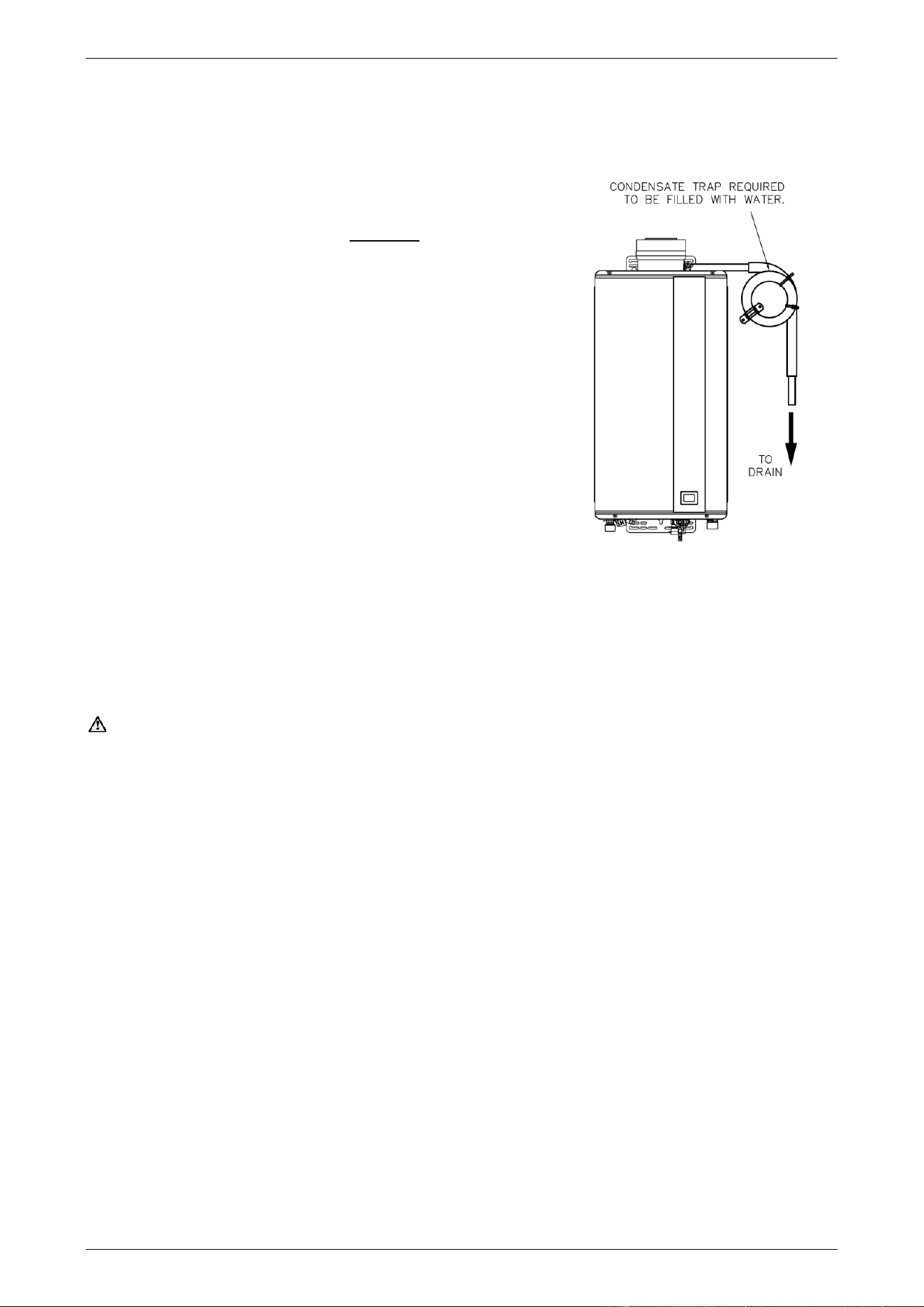
FLUEING
37
Condensate Trap and Condensate Drain Line
Where the installation requires a Condensate Trap and condensate drain line:
1. Remove the clamp and rubber cap from the condensate drain spigot on the water heater flue outlet
assembly.
2. Locate the Condensate Trap in a suitable position adjacent to
the water heater.
The loop of the condensate trap MUST BE below the spigot
of the condensate drain section to ensure proper drainage.
▪ Secure to the wall with the pipe saddle supplied.
If required, trim the hose length to suit the installation. Ensure
the structure of the Condensate Trap including the fixed loop
is not altered and the trimmed hose seals to the spigot.
3. Fill the condensate trap with water.
4. Fit the shorter end of the silicone tube to the 16 mm spigot of
the water heater flue outlet, ensuring a constant fall to the
condensate trap.
▪ Secure to the spigot with the clamp removed in step 1.
▪ Ensure the silicon hose is not kinked.
5. Plumb the outlet of the Condensate Trap to drain.
▪ Ensure the silicon hose is not kinked.
The drain line should be as short as possible, have a continuous fall all the way from the Condensate Trap
to the discharge outlet and have no tap, valves or other restrictions in the pipe work.
The outlet of the drain line must be in such a position that flow can be easily seen, but arranged so the
condensate will not cause injury, damage or nuisance.
Warning: Failure to fill with water may cause flue gasses to escape through the condensate trap. Check
regularly to ensure the condensate trap is filled with water, replenishing when required.
Notes
Consideration must be given to the material used for a condensate drain line and to where the drain line
discharges.
• As the condensate is mildly acidic, copper tube and fittings must not be used as they will corrode.
• Use UPVC (Unplasticised Polyvinyl Chloride) or PE (polyethylene) piping.
• The outlet of the drain line must be in such a position that flow can be easily seen, but arranged so that
discharge will not cause injury, damage or nuisance.
• The drain line must not discharge onto electrical connections, earth stakes, copper pipe, concrete paths
or into a pond.
For a multiple unit installation, refer to “Multiple Water Heater Condensate Trap and Condensate Drain Line
Installation” on page 48.
Condensate Trap and Condensate Drain Line
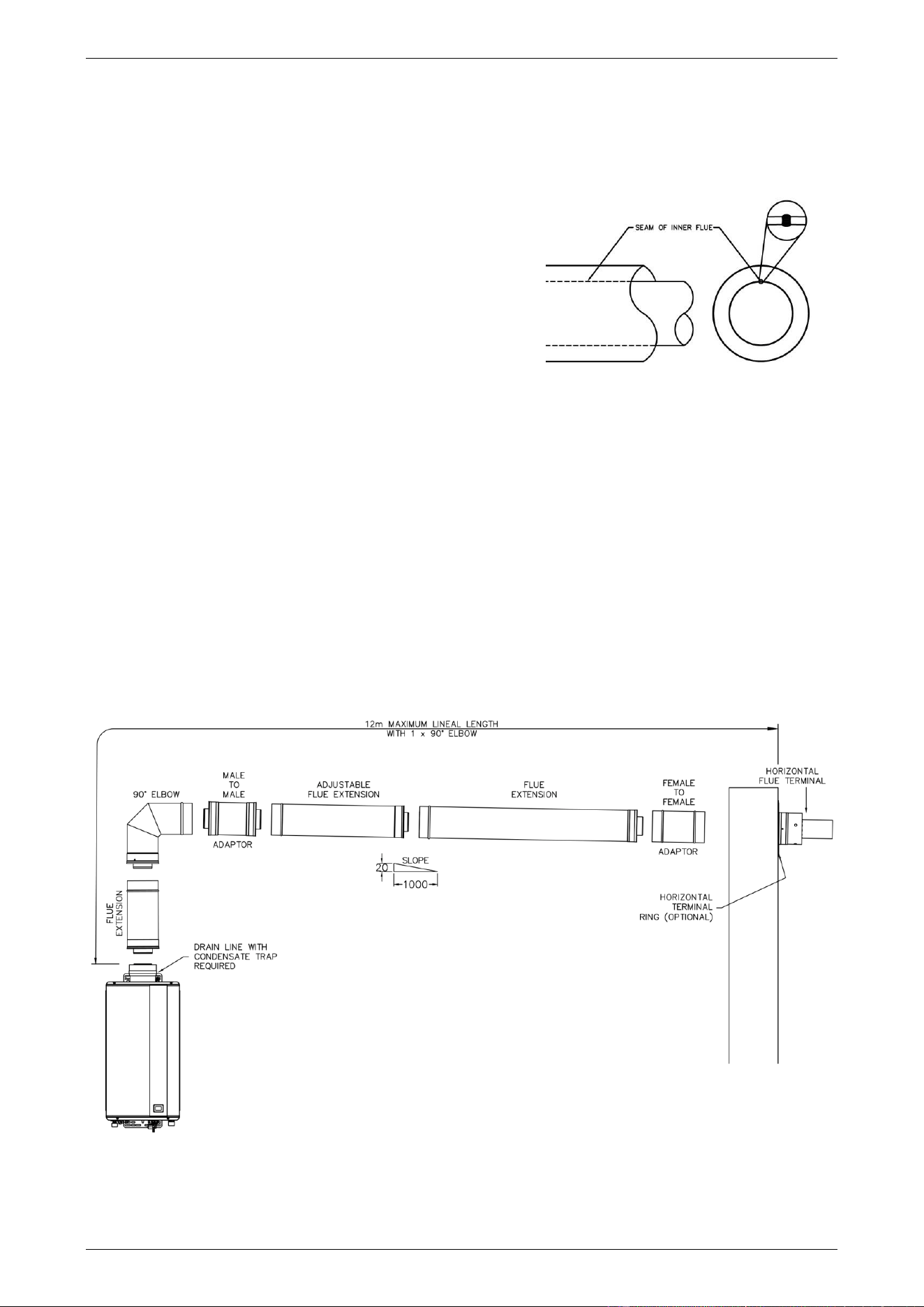
FLUEING
38
HORIZONTAL FLUE RUNS
There are a number of basic installation requirements which must be followed for a flue installation
incorporating horizontal flue runs.
Failure to observe these precautions can lead to the premature failure of the flue system and / or water
heater.
• The flue must be installed with the seam of the inner flue
toward the top of the installation.
• A horizontal section of flue must be installed with a
gradient of 20 mm per metre (1 in 50 or 1° fall) of
horizontal run.
• A horizontal run of flue between two elbows where the
elbow closest to the flue terminal is orientated upward,
must have a gradient upward to the flue terminal.
▪ Condensate will drain back toward the water heater. A Condensate Trap and drain line must be
installed where the horizontal flue is installed with an upward gradient. Refer to “Draining the
Condensate” on page 36.
This ensures any condensate formed during operation of the water heater is prevented from draining
back into the water heater.
• A horizontal run of flue connecting directly to a Horizontal Flue Terminal must have a gradient downward
to the flue terminal.
This prevents rainwater from entering the flue draining back into the water heater.
▪ Use Male to Male and Female to Female Adaptors to reverse the direction of flue insertion where
three or more sections of flue are used in a horizontal flue run and the flue drains toward the flue
terminal. Refer to the diagram “Typical Installation – Horizontal Flue with One Elbow” on page 38.
This provides for proper draining of condensate without pooling at the flue component joins.
Typical Installation – Horizontal Flue with One Elbow
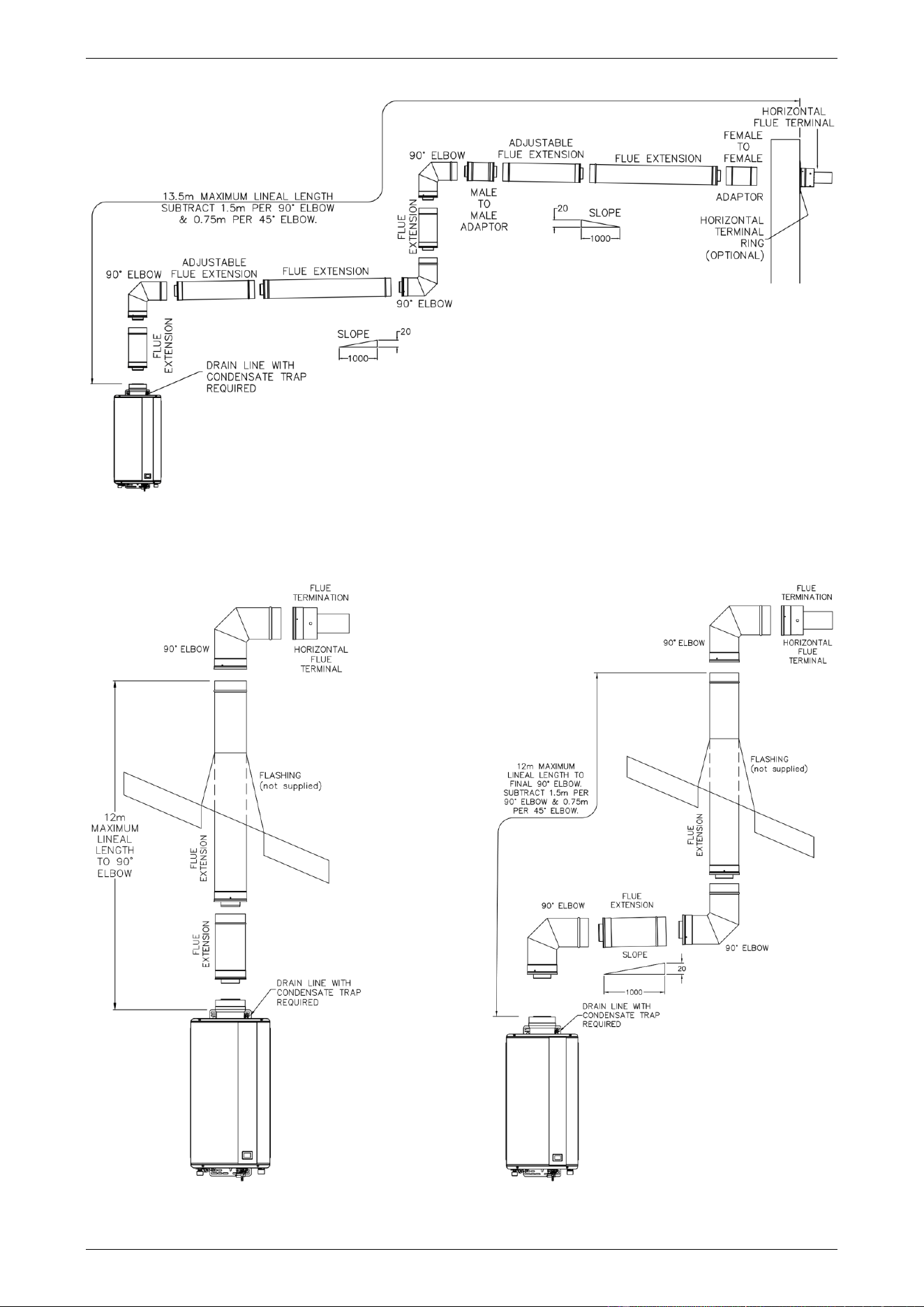
FLUEING
39
Typical Installation
Horizontal Flue with Multiple Vertical and Horizontal Sections
Typical Installation Typical Installation
Vertical Flue Vertical Flue with Vertical and Horizontal Sections
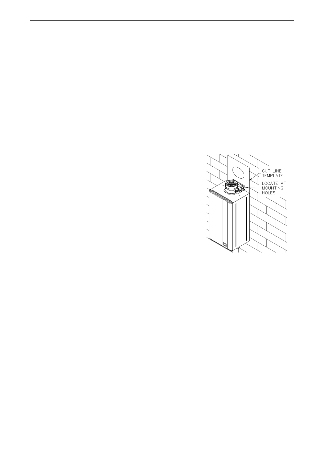
FLUEING
40
HORIZONTAL FLUE INSTALLATION
Horizontal Flueing – Directly Behind Water Heater
This method of flue installation is used where the secondary flue is to penetrate and terminate immediately
behind the wall on which the water heater is mounted.
Do not plumb the water heater prior to this type of flue installation, as the water heater (if mounted) requires
to be removed from the wall prior to the final installation of the flue.
Notes
• Ensure each flue component is fully engaged and the rubber seal on the inner duct is well seated at each
joint.
• Each flue component is supplied with screws to connect to the adjacent flue component. The screws are
located in a bag taped to the outside of the flue component.
To install a horizontal flue and termination directly behind the water heater:
1. Carefully remove the template inserted as the middle pages of this installation instructions booklet.
2. Align the mounting bracket holes on the template exactly over
the upper wall mounting bracket holes on the water heater.
This step presumes the water heater is hung on the wall.
▪ It may be convenient to tape the template to the wall.
Note: Ensure there are no studs, noggins, pipes or electrical
cables located in the wall where the flue is to penetrate
3. Mark the pilot hole location through the centre of the template.
▪ Remove but DO NOT DISCARD the template.
4. Remove the water heater from the wall.
Note: It is necessary to remove the water heater from the wall to
allow the fitting and installation of the flue. It is also good practice
so no debris from the drilling operation enters the water heater
flue outlet.
5. Drill a pilot hole using a 6.5 mm diameter or smaller drill bit.
The drill bit must be long enough to penetrate completely through the outer skin of the external wall.
Note: Ensure the drill remains level and straight during this step.
6. Cut along the middle of the bold circle marked “Cut Line” on the template.
7. Align the centre of the template with the pilot hole on the wall surface and scribe around the template onto
the wall.
The circle should be 150 mm in diameter.
▪ Remove but DO NOT DISCARD the template.
8. Align the centre of the template with the pilot hole on the outside wall surface and scribe around the
template onto the wall.
The circle should be 150 mm in diameter.
▪ Remove the template.
9. Drill or cut the flue termination hole through the wall using a cutting tool suitable for the wall construction.
Note: The Trim Ring (PN 295125) will cover a 150 mm diameter hole.
position template
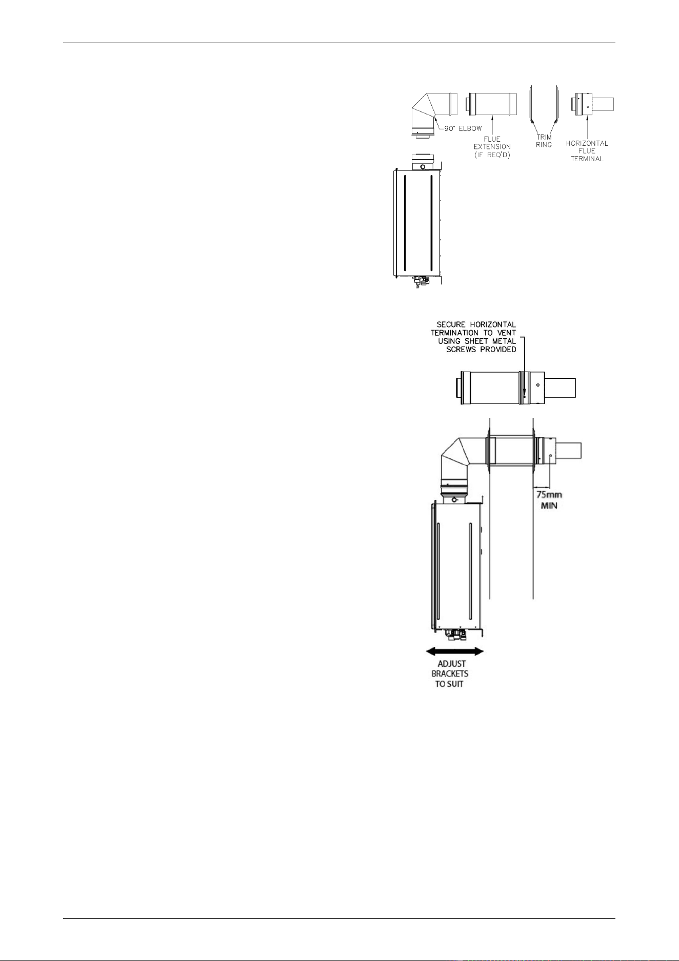
FLUEING
41
Note: Steps 10 to 14 can only be conducted whilst the water heater is off the wall.
10. Connect the 90° Elbow (PN 295147) to the water heater
flue outlet so it is orientated behind the water heater.
◼ Fit the end of the elbow down over the water heater
flue outlet as far as it will go.
Ensure there is a minimum 35 mm and maximum
42 mm overlap, the rubber seal on the inner flue is
well seated and the elbow is fully engaged on the
water heater flue outlet.
◼ Secure the elbow to the outlet with the screws
provided.
11. Fit the 300 mm Flue Extension (PN 295152) to the
90° Elbow, if required.
Note: A total wall thickness of greater than 170 mm will
require a 300 mm Flue Extension.
12. Fit the Horizontal Flue Terminal (PN 295146) to either the
90° Elbow or 300 mm Flue Extension.
13. Secure each flue component using the sheet metal screws
provided.
14. Fit a Trim Ring over the last section of flue.
15. Rehang the water heater on the wall, carefully inserting
the flue assembly through the wall penetration.
The water heater should be installed in its final location
and fixed in position before completing the flue installation.
Securely fasten the water heater to the wall at each of the
Wall Bracket mounting points.
Adjust the mounting brackets at the top and bottom of the
water heater if required. Bracket adjustment of up to
30 mm can be made and may assist with flue fitment and
alignment.
16. Check the end of the outer skin of the flue terminal extends
a minimum of 75 mm from the face of the external wall.
17. Apply an adequate bead of sealant around the flue
assembly and exterior wall of the building, using a general
purpose silicone sealant suitable for outdoor application.
Failure to properly seal the flue penetration through the
wall will result in long term damage due to weather
conditions.
18. Apply an adequate bead of sealant on the rear face of a Trim Ring, using a general purpose silicone
sealant suitable for outdoor application.
▪ Fit the Trim Ring over the flue terminal and press against the wall.
19. Apply an adequate bead of sealant around the flue assembly and interior wall of the building and on the
rear face of the Trim Ring, using a general purpose silicone sealant suitable for indoor application.
Press the Trim Ring against the wall.
Refer to “Connections – Electrical” on page 50 electrical connection details and “Commissioning” on page 57
for the commissioning details of the water heater.
flue components required
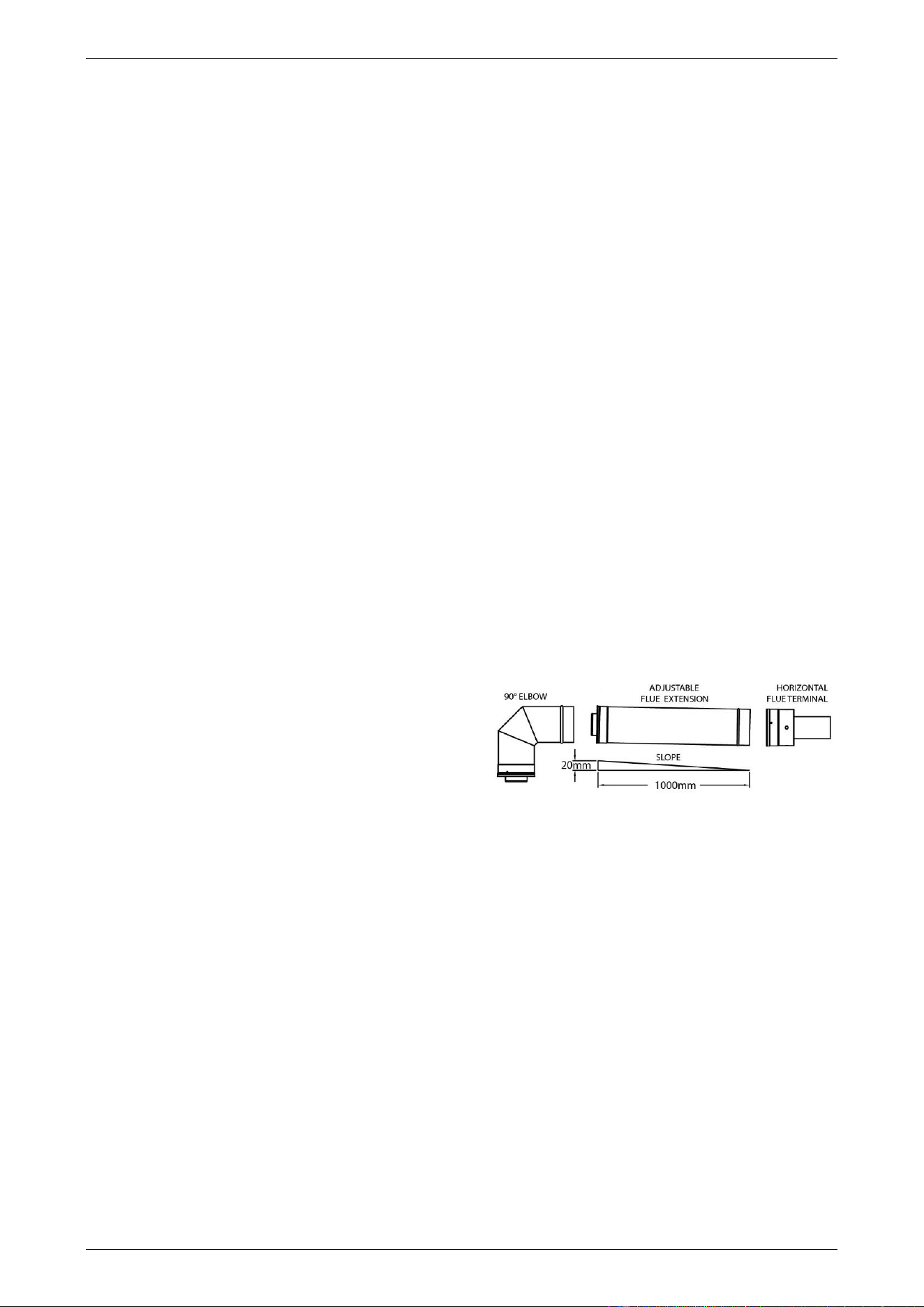
FLUEING
42
Horizontal Flueing – Extended Flue Run
Notes
• Ensure each flue component is fully engaged and the rubber seal on the inner duct is well seated at each
joint.
• Each flue component is supplied with screws to connect to the adjacent flue component. The screws are
located in a bag taped to the outside of the flue component.
• Refer to diagrams:
▪ “Typical Installation – Horizontal Flue with One Elbow” on page 38, and
▪ “Typical Installation – Horizontal Flue with Multiple Vertical and Horizontal Sections” on page 39.
To install an extended horizontal flue and termination:
1. Install the water heater in its final location.
2. Connect the 90° Elbow (PN 295147) to the water heater flue outlet and rotate in the desired direction of
discharge, if the flue is not to have a change of direction from horizontal to vertical.
▪ Fit the end of the elbow down over the water heater flue outlet as far as it will go.
Ensure there is a minimum 35 mm and maximum 42 mm overlap, the rubber seal on the inner flue is
well seated and the elbow is fully engaged on the water heater flue outlet.
▪ Secure the elbow to the outlet with the screws provided.
3. Mark the location where the top of the flue is to penetrate the wall to outside of the building.
If the flue is not to have a change of direction from horizontal to vertical, then to accurately mark this
position:
▪ Measure the vertical distance from the floor to
the top of the 90° Elbow, and
▪ Measure the horizontal distance from the wall
behind the water heater to the centre of the
90° Elbow, and
▪ Then, where the flue is expected to penetrate
the wall, mark the vertical distance up from the
floor and the horizontal distance out from the
wall measured from the previous steps.
Note: If the flue is to have an additional one or two horizontal changes of direction, then it is not
necessary to measure or mark the horizontal distance from the wall behind the water heater to the
centre of the 90° Elbow.
▪ Alternatively, using a level, run from the top of the 90° Elbow to a location horizontal on the wall where
the flue will penetrate and mark this point on the wall
▪ Measure the horizontal distance, along the proposed flue route, from the end of the 90° Elbow to the
where the flue is to penetrate the wall.
Divide this measurement by 50 to calculate the vertical distance fall of the flue (allowing for a 1 in 50
fall).
▪ Measure this distance down from the previous mark placed on the wall.
This point will be the top of the flue termination hole and the flue will have a gradient of 20 mm per
metre of length towards the terminal.
Note: Ensure there are no studs, noggins, pipes or electrical cables located in the wall where the flue is
to penetrate
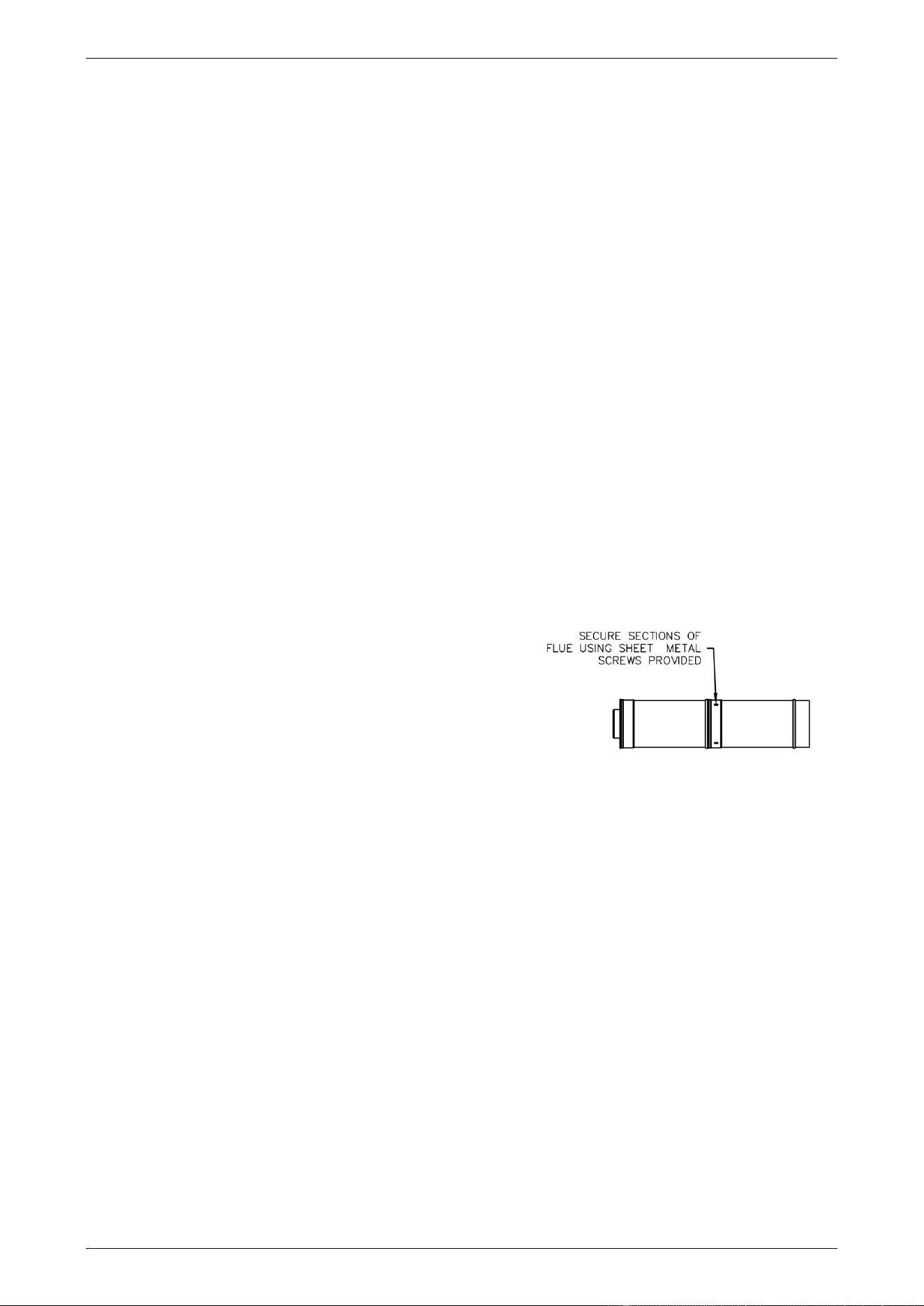
FLUEING
43
4. Carefully remove the template inserted as the middle pages of this installation instructions booklet.
▪ Cut along the middle of the bold circle marked “Cut Line”.
5. Align the top of the circular template with the mark on the wall.
◼ It may be convenient to tape the template to the wall.
6. Mark the pilot hole through the centre of the template and scribe around the template onto the wall.
The scribed circle should be 150 mm in diameter.
▪ Remove but DO NOT DISCARD the template.
7. Drill a pilot hole using a 6.5 mm diameter or smaller drill bit.
The drill bit must be long enough to penetrate completely through the outer skin of the external wall.
Note: Ensure the drill remains level and straight during this step.
8. Align the centre of the template with the pilot hole on the outside wall surface and scribe around the
template onto the wall.
The scribed circle should be 150 mm in diameter.
▪ Remove the template.
9. Drill or cut the flue termination hole through the wall using a cutting tool suitable for the wall construction.
Note: The Trim Ring (PN 295125) will cover a 150mm diameter hole.
10. Starting from the 90° Elbow and working towards the terminal location, connect all of the other flue system
components.
▪ Ensure each flue component is fully engaged and the
rubber seal on the inner duct is well seated at each
joint.
11. Secure each flue component using the sheet metal
screws provided.
12. Support horizontal sections at a distance no greater than
2 m using a Wall Bracket (PN 295129).
13. A horizontal run of flue connecting directly to a Horizontal Flue Terminal must have a downward gradient
to the flue terminal.
▪ Use Male to Male and Female to Female Adaptors to reverse the direction of flue insertion where
three or more sections of flue are used in a horizontal flue run and the flue drains toward the flue
terminal. Refer to the diagram on page 38.
This provides for proper draining of condensate without pooling at the flue component joins.
14. A horizontal run of flue between two elbows where the elbow closest to the flue terminal is orientated
upward, must have a gradient upward in the direction of the flue terminal.
Note: A Condensate Trap and condensate drain line must be installed if the flue has a gradient upward
in the direction of the flue terminal. Refer to step 22.
15. The Adjustable Flue Extension (PN 295153) may be required if a special length is required between offsets
or changes in direction of the flue or to ensure the outer skin of the Horizontal Flue Terminal extends a
minimum of 75 mm from the face of the external wall.
▪ The Adjustable Flue Extension can be adjusted from 560 mm to 890 mm by pulling on its end to
increase its length or pushing on its end to decrease its length.
16. Fit a Trim Ring over the last section of flue prior to penetrating the wall.
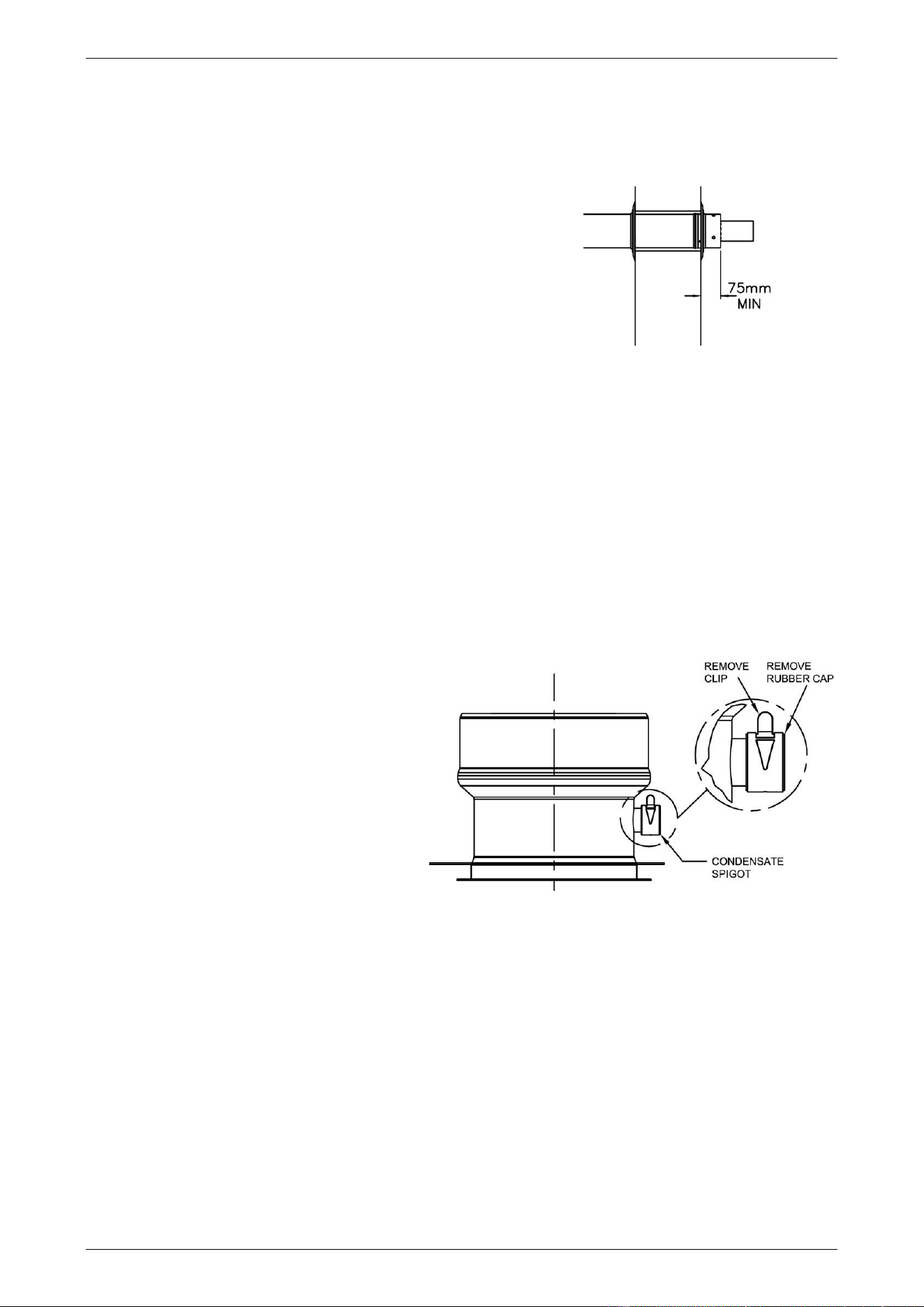
FLUEING
44
17. Once the flue is assembled and penetrating the wall, install the Horizontal Flue Terminal and secure the
termination to the flue using the sheet metal screws provided.
Note: If the flue terminal position is more than 1800 mm above a safe working surface, then suitable
equipment will be required to enable safe access to fit the flue terminal.
Alternatively, the flue terminal may be fitted to the flue
assembly prior to the assembly penetrating the wall.
18. Make a final adjustment to the Adjustable Flue Extension,
if required, to ensure the end of the outer skin of the flue
terminal extends a minimum of 75 mm from the face of the
external wall.
▪ Firmly tighten the compression band on the
Adjustable Flue Extension to prevent the pipe from
extending or compressing its length over time.
19. Apply an adequate bead of sealant around the flue assembly and exterior wall of the building, using a
general purpose silicone sealant suitable for outdoor application.
Failure to properly seal the flue penetration through the wall will result in long term damage due to weather
conditions.
20. Apply an adequate bead of sealant on the rear face of a Trim Ring, using a general purpose silicone
sealant suitable for outdoor application.
▪ Fit the Trim Ring over the flue terminal and press against the wall.
21. Apply an adequate bead of sealant around the flue assembly and interior wall of the building and on the
rear face of the Trim Ring, using a general purpose silicone sealant suitable for indoor application.
Press the Trim Ring against the wall.
22. Install a Condensate Trap (PN 295139) to
the condensate drain spigot on the water
heater flue outlet if the flue has a change
of direction from horizontal to vertical or if
there is a long vertical rise directly from the
water heater.
▪ Install a condensate drain line to the
Condensate Trap.
Refer to “Draining the Condensate” on
page 36 and to “Condensate Trap and
Condensate Drain Line” on page 37.
23. Upon completion of the secondary flue
installation, remove the warning label
adhered to the top left hand corner of the
water heater’s front panel.
Refer to “Connections – Electrical” on page 50 electrical connection details and “Commissioning” on page 57
for the commissioning details of the water heater.
condensate drain spigot
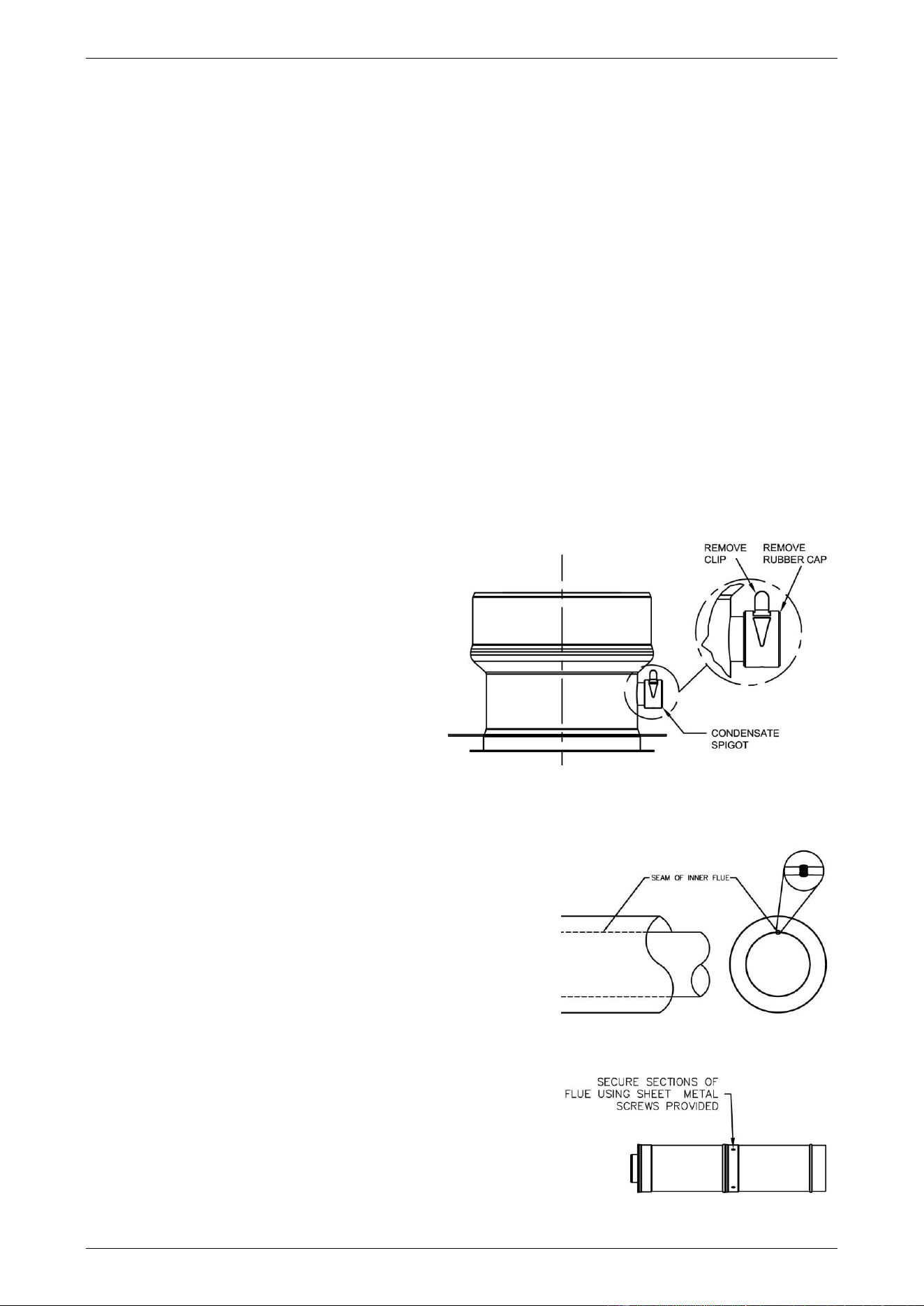
FLUEING
45
VERTICAL FLUE INSTALLATION
Suitable flashing (not supplied) is required to waterproof the roof penetration.
Notes
• Ensure each flue component is fully engaged and the rubber seal on the inner duct is well seated at each
joint.
• Each flue component is supplied with screws to connect to the adjacent flue component. The screws are
located in a bag taped to the outside of the flue component.
• Refer to diagrams:
▪ “Typical Installation – Vertical Flue” on page 39, and
▪ “Typical Installation – Vertical Flue with Vertical and Horizontal Sections” on page 39.
To install a vertical flue and termination:
1. Determine the location where the flue will penetrate through the roof.
Note: Ensure there are no rafters, purlins, pipes or electrical cables located in the roof where the flue is
to penetrate.
2. Drill or cut the flue termination holes through the roof and ceiling of a suitable size to allow the installation
of the flue, using a cutting tool suitable for the roof construction.
3. Install a Condensate Trap (PN 295139) to the
condensate drain spigot on the water heater
flue outlet.
▪ Install a condensate drain line to the
Condensate Trap.
Refer to “Draining the Condensate” on
page 36 and to “Condensate Trap and
Condensate Drain Line” on page 37.
4. Connect the first flue component to the water
heater flue outlet.
▪ Fit the end of the flue component down
over the water heater flue outlet as far as
it will go.
Ensure there is a minimum 35 mm and maximum 42 mm
overlap, the rubber seal on the inner flue is well seated
and the flue component is fully engaged on the water
heater flue outlet.
▪ Secure the elbow to the outlet with the screws provided.
5. Continuing from the first flue component and working towards
the terminal location, connect all of the other flue system
components.
▪ Ensure each flue component is fully engaged and the
rubber seal on the inner duct is well seated at each joint.
6. Horizontal flue runs between elbows must have a minimum
upward gradient towards the flue terminal of 20 mm per metre.
Note: Ensure that the seam of the inner flue in horizontal runs
is towards the top of the installation.
7. Secure each flue component using the sheet metal screws
provided.
condensate drain spigot
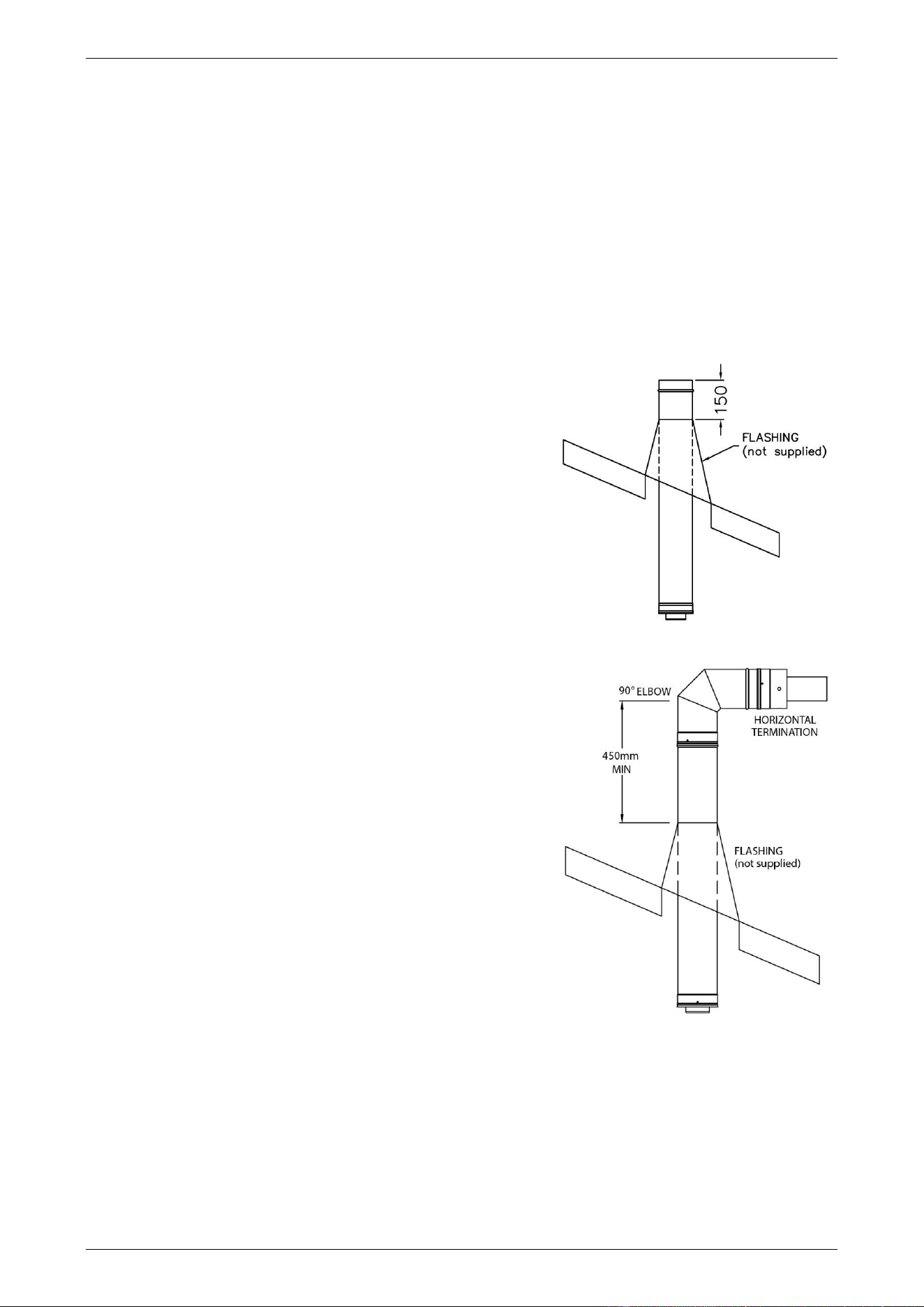
FLUEING
46
8. Fix a Wall Bracket after each transition to a vertical run.
This is to prevent vertical loading on the elbows and offsets.
9. Support vertical sections of flue at a distance no greater than 2 m using a Wall Bracket (PN 295128).
Note: The Wall Bracket can be used to support vertical sections of flue from a ceiling by rotating the legs
through 90°.
10. Install an Adjustable Flue Extension (PN 295153) if a special length is required between offsets or changes
in direction of the flue.
▪ The Adjustable Flue Extension can be adjusted from 560 mm to 890 mm by pulling on its end to
increase its length or pushing on its end to decrease its length.
▪ Firmly tighten the compression band on the Adjustable Flue Extension to prevent the pipe from
extending or compressing its length over time.
11. Fit a Trim Ring over the last section of flue prior to penetrating
the ceiling, if one is to be fitted.
12. Once all the flue components, excluding the 90° Elbow
(PN 295147) and Horizontal Flue Terminal (PN 295146), have
been installed and all supports are securely fastened, the roof
flashing must be installed and adequately sealed to prevent
rain entry.
▪ Cut the flashing to a diameter that allows a snug fit over
the flue.
▪ Install the roof flashing over the flue and using suitable
fasteners, fix to the roof material.
The flue must extend a minimum of 150 mm through the
roof flashing.
13. Connect the 90° Elbow to the flue exiting the roof, and the
Horizontal Flue Terminal to the 90° Elbow.
▪ Secure the joints with sheet metal screws provided.
The bottom of the Horizontal Flue Terminal should not be less
than 450 mm above the flashing below.
Observe flue terminal clearances in accordance with
AS/NZS 5601.1. Refer also to “Vertical Flue Terminal
Location” on page 35.
Note: The flue should not extend more than 1.5 m from the
roof unless guy wires or other additional support is provided.
14. Apply an adequate bead of sealant around the flue assembly
and flashing and around the flashing and roof material, using
a general purpose silicone sealant suitable for outdoor
application.
Failure to properly seal the flue penetration through the roof
will result in long term damage due to weather conditions.
15. Apply an adequate bead of sealant around the flue assembly and ceiling and on the rear face of the Trim
Ring (if fitted), using a general purpose silicone sealant suitable for indoor application.
Press the Trim Ring (if fitted) up against the ceiling.
16. Upon completion of the secondary flue installation, remove the warning label adhered to the top left hand
corner of the water heater’s front panel.
Refer to “Connections – Electrical” on page 50 electrical connection details and “Commissioning” on page 57
for the commissioning details of the water heater.
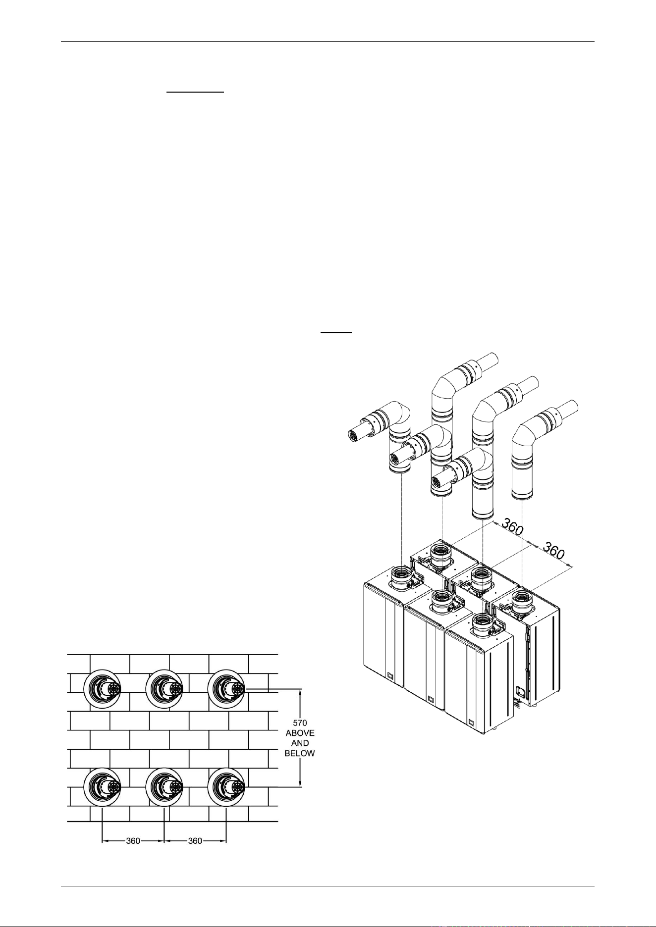
FLUEING
47
MULTIPLE WATER HEATER FLUE INSTALLATION
Where multiple water heaters are installed, each water heater must be individually flued to the outside. A
common flue system MUST NOT be used.
For a multiple unit installation, the water heater is certified for installation with zero clearance between adjacent
water heaters.
If the water heaters are mounted on a wall, although they are certified for installation with zero clearance
between them, it may be necessary to leave a suitable space of a minimum 175 mm between each water
heater if a Condensate Trap and condensate drain line is to be installed. The Condensate Trap and condensate
drain line would located between each water heater with the common drain manifold positioned below the
water heaters. Refer to “Multiple Water Heater Condensate Trap and Condensate Drain Line Installation” on
page 48.
Refer to “Flue Terminal Location” on page 35 for flue terminal clearances from other objects in accordance
with AS/NZS 5601.1.
Follow the relevant instructions pertaining to the type of flue installation, with the following additional
requirements in relation to flue terminal clearances to be taken into account. The distances are based on using
the coaxial flue system components.
Note: All flues for a multiple water heater installation MUST terminate horizontally.
Multiple Flue Terminations through Roof
1. The minimum side by side centre to centre
distance between flue terminals is to be no less
than 360 mm.
2. Each flue is to be terminated horizontally by using
a 90° Elbow (PN 295147) and a Horizontal Flue
Terminal (PN 295146).
3. Refer to “Vertical Flue Terminal Location” on
page 35 for the minimum distances of the flue
terminals from the roof and other structures.
4. The flue terminals for back to back water heaters
are to be installed at 180° to each other.
Multiple Flue Terminations through Wall
1. The minimum horizontal centre to centre
distance between flue terminals is to be no less
than 360 mm.
2. The minimum vertical centre to centre distance
between flue terminals is to be no less than
570 mm.
multiple flue terminations through wall
multiple flue terminations through roof
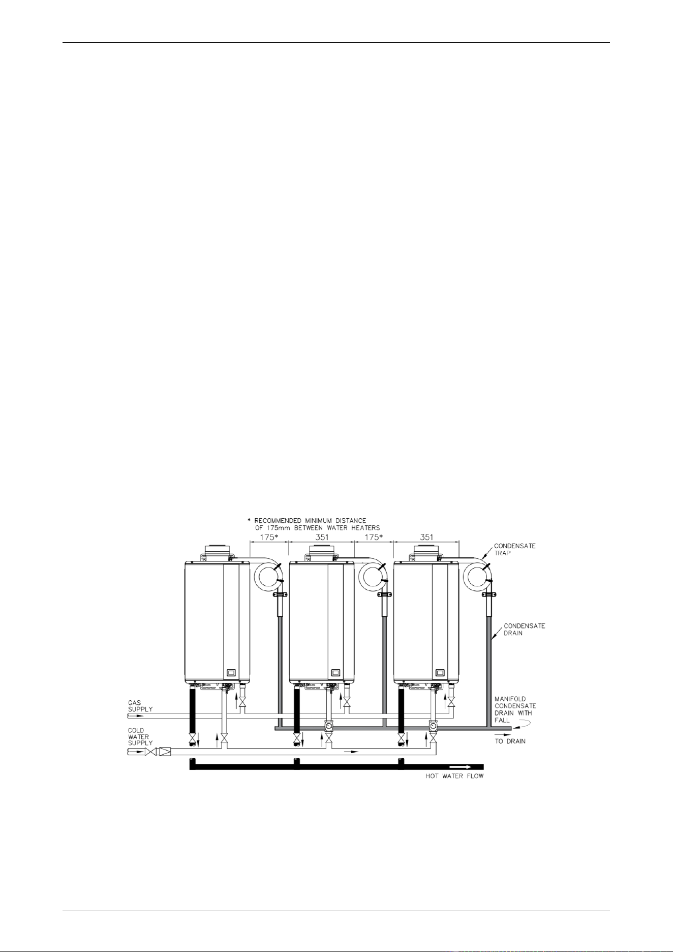
FLUEING
48
MULTIPLE WATER HEATER CONDENSATE TRAP AND CONDENSATE DRAIN LINE INSTALLATION
Depending upon the type of installation, it may be necessary to install a Condensate Trap and condensate
drain line to each water heater. Refer to “Draining the Condensate” on page 36.
The drain line from each Condensate Trap may be:
• drained separately to a discharge point, or
• manifolded together with a single drain line running to a discharge point.
If the water heaters are mounted on a wall, although they are certified for installation with zero clearance
between them, it may be necessary to leave a suitable space of a minimum 175 mm between each water
heater if a Condensate Trap and condensate drain line is to be installed. The Condensate Trap and condensate
drain line would located between each water heater with the common drain manifold positioned below the
water heaters.
Condensate Traps with Common Drain Line
1. Remove the clamp and rubber cap from the condensate drain spigot on each water heater flue outlet
assembly.
2. Locate and install the Condensate Trap in a suitable position adjacent to the water heater.
Refer to steps 2 to 4 of the procedure outlined in “Condensate Trap and Condensate Drain Line” on
page 37.
If the drain line from each Condensate Trap is to be run separately to a discharge point, then proceed to
step 4, otherwise continue with step 3.
3. Manifold the drain lines from each Condensate Trap into a common header.
Use UPVC, PE or similar, do not use copper.
Ensure adequate fall is provided in the header to allow for complete drainage.
It may be necessary to support the drain line manifold with suitable hangers from the ceiling.
condensate drain common manifold
4. Plumb the outlet of each Condensate Trap or the drain line manifold to a suitable discharge point.
The drain line should be as short as possible, have a continuous fall all the way from the Condensate Trap
or drain line manifold to the discharge outlet and have no tap, valves or other restrictions in the pipe work.
The outlet of the drain line must be in such a position that flow can be easily seen, but arranged so the
condensate will not cause injury, damage or nuisance.

FLUEING
49
Warning: Failure to fill with water may cause flue gasses to escape through the condensate trap. The
condensate trap should be regularly checked to ensure it is filled with water, replenishing when required.
Notes
Consideration must be given to the material used for a condensate drain line and to where the drain line
discharges.
• As the condensate is mildly acidic, copper tube and fittings must not be used as they will corrode.
• Use UPVC (Unplasticised Polyvinyl Chloride) or PE (polyethylene) piping.
• The outlet of the drain line must be in such a position that flow can be easily seen, but arranged so that
discharge will not cause injury, damage or nuisance.
• The drain line must not discharge onto electrical connections, earth stakes, copper pipe, concrete paths
or into a pond.
50
CONNECTIONS – ELECTRICAL
All electrical work and permanent wiring must be carried out by a qualified person and in accordance with the
Wiring Rules AS/NZS 3000 and all local codes and regulatory authority requirements.
Warning: Temperature controllers must not be fitted to this water heater (864 series) if it is installed as an
in-series gas booster with a solar water heater system because water at a temperature much higher than the
controller setting can be delivered. If a solar water heater has been installed to an existing water heater
installation, then all controllers must be disconnected and removed.
The water heater is supplied with a 1.8 metre lead and plug and requires a 220 - 240 V a.c. 50 Hz general
purpose outlet (GPO) to be located within 1.2 metres of the installation. The GPO must be clear of the flue
exhaust, draining water, gas supply pipe and water connections.
The power consumption of the water heater is:
Models
Power
consumption
Comments
864B28 and 866B28 models
natural gas
@ 220 V – 240 V a.c. 50 Hz
< 1 Watt
Burner off, anti-frost device inactive
95 Watts
Burner off, anti-frost device active
77 Watts
Burner on, anti-frost device inactive
The water heater will only operate on a sine wave at 50 Hz. Devices generating a square wave cannot be used
to supply power to the water heater.

CONNECTIONS – ELECTRICAL
51
WIRING DIAGRAM
Wiring Diagram – 864, 866 Series B28 Models
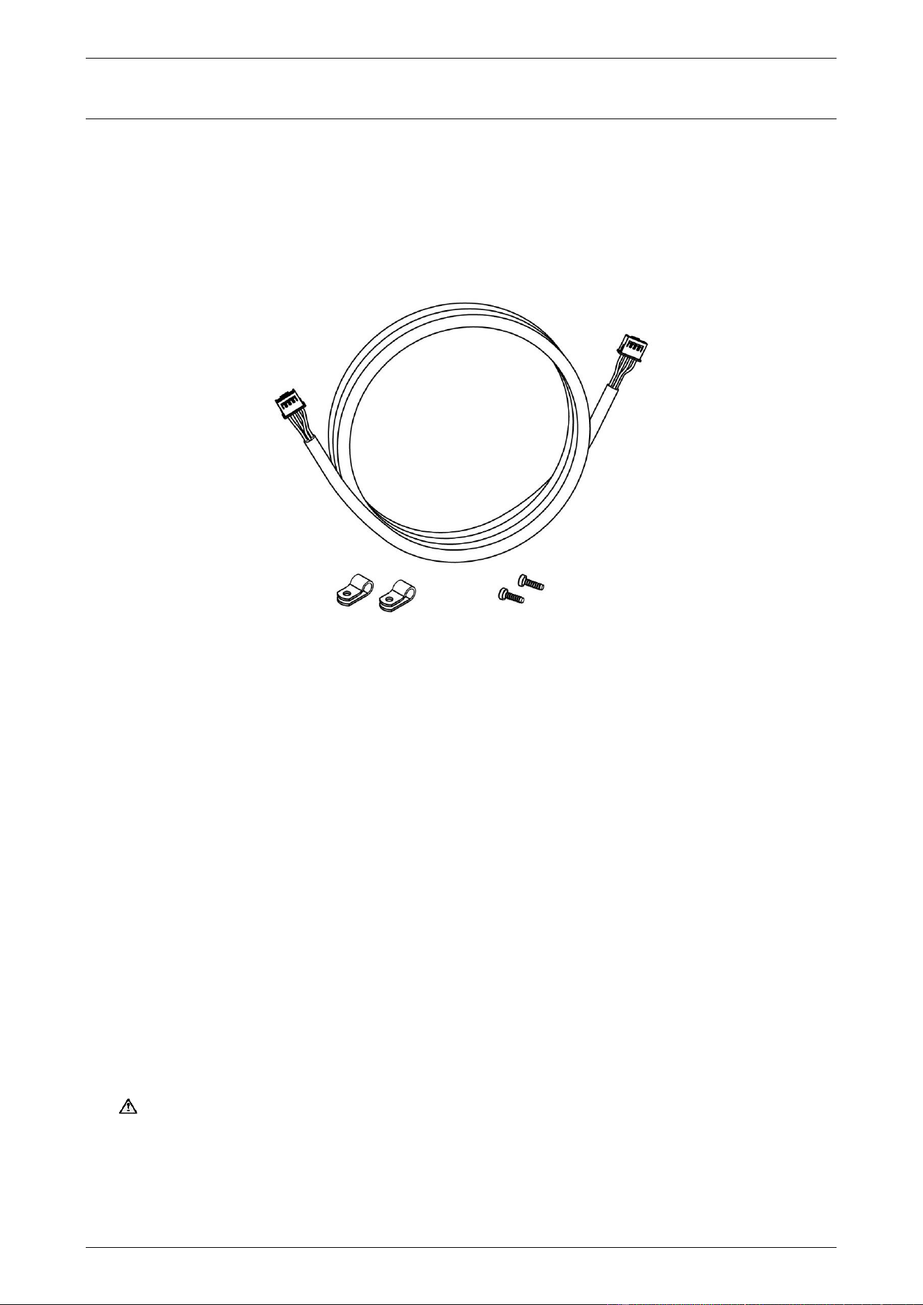
52
EZ LINK SYSTEM DUAL INSTALLATION
The EZ Link
®
system is designed to electronically control two gas continuous flow water heaters and have
them operate as one. One or both water heaters may be in operation, depending upon the hot water demand.
The second water heater will only operate when the hot water demand exceeds the capacity of the first water
heater to supply.
The EZ Link system is suitable for installation with Rheem 864 and 866 series B28 model gas continuous flow
water heaters. The EZ Link Kit PN 299291 is required for the installation.
plus installation instructions PN 122675
EZ Link Kit – PN 299291
Notes
• Only two gas continuous flow water heaters can be installed with an EZ Link system.
• The EZ Link system will vary the start-up sequence of the two water heaters.
• The two continuous flow water heaters must be of the same model. The performance of two different
model water heaters manifolded together cannot be guaranteed.
• It is recommended the two water heaters be set with the same preset outlet temperature setting.
• A Rheem temperature controller(s) may be installed but is not required to be installed with the EZ Link
system on a Rheem 864 and 866 series B28 model dual installation.
• If the EZ Link system is used with a water heater with a preset outlet temperature greater than 60°C and
a temperature controller is installed, the maximum outlet temperature of the water heater will be limited
by the maximum temperature setting of the temperature controller.
• Two Rheem 864B28 model water heaters manifolded together and with an EZ Link system installed can
be used as an in-series gas booster system to a solar water heater installation so long as a temperature
controller is not installed.
Warning: Temperature controllers must not be fitted to a water heater (864 series) if it is installed as
an in-series gas booster with a solar water heater system because water at a temperature much higher
than the controller setting can be delivered.
screws x 2
cable clamps
x 2
EZ Link cable x 1

EZ LINK SYSTEM DUAL INSTALLATION
53
DUAL INSTALLATION
The two water heaters can be installed side by side with minimal clearance between them. Rheem 864 and
866 series B28 models are certified for installation with an exemption from the 300 mm minimum clearance
requirements between flue terminals, as stated in AS/NZS 5601.1 clause 6.9.3.
Install two water heaters of the same model in a parallel plumbing arrangement. It is good practice, but not
essential, to install the two water heaters in an Equa-Flow
®
manifold plumbing arrangement. There are basic
installation requirements which must be followed:
1. The pipe work must be sized to meet the requirements of both AS/NZS 3500.4 and the application. It is
recommended to use minimum DN25 pipe for the cold water line, cold and hot headers and hot water line
and DN20 for the cold and hot water branch lines of each water heater.
2. A full flow gate valve or ball valve must be installed on the cold water line to the system. A non-return
valve or stop tap must not be installed.
3. A full flow gate valve or ball valve (not a stop tap) should be installed on both the cold water branch and
hot water branch of each water heater.
4. An isolation valve must be installed on the gas branch of each water heater.
5. Non-return valves or pressure limiting valves must not be installed on the branch lines to the water heaters.
6. All fittings, valves and branch lines should be matched sets to each of the water heaters.
7. Sufficient space must be left to enable access, servicing or removal of either water heater.
Refer to the ‘Typical Two Unit Manifold with EZ Link Connection’ diagram on page 56 for installation and plant
layout details.
RATING LABEL INFORMATION
There is information on the rating label located on the right hand side of the water heater, which may be
required for future warranty and service requirements. This information will be hidden on the left hand water
heater if the two water heaters are installed with minimal clearance between them.
Move the rating label to or indelibly copy the water heater serial number, manufacture date and model number
from the label onto the left hand side or front panel of the left hand water heater or to another position which
is visible when the water heater is installed so the householder or responsible officer can access the water
heater details when required.
A second rating label is attached to the inside of the front cover. This is for a service person to access the
water heater details when required.
TEMPERATURE CONTROLLER
A temperature controller(s) may be installed but is not required to be installed on the Rheem 864 and
866 series B28 model water heaters with the EZ Link system.
Warning: Temperature controllers must not be fitted to a water heater (864 series) if it is installed as an
in-series gas booster with a solar water heater system because water at a temperature much higher than the
controller setting can be delivered.
Connect a temperature controller to one only of the two water heaters. Up to three temperature controllers of
the same family can be installed to this water heater. Refer to the Owner’s Guide and Installation Instructions
of the controllers for the procedure to connect the controller(s).
The water heater connected with the temperature controller(s) will become the ‘master’ water heater. The
installed temperature controller(s) will control the temperature and functionality of both water heaters.
The maximum outlet temperature of the water heaters will be limited by the maximum temperature setting of
the temperature controller.
A temperature controller should not be installed if two 864 series B28 model water heaters are installed with
an EZ Link system and they are part of a circulated hot water flow and return system in a building. Refer to
“Circulated Hot Water Flow and Return System” on page 25.
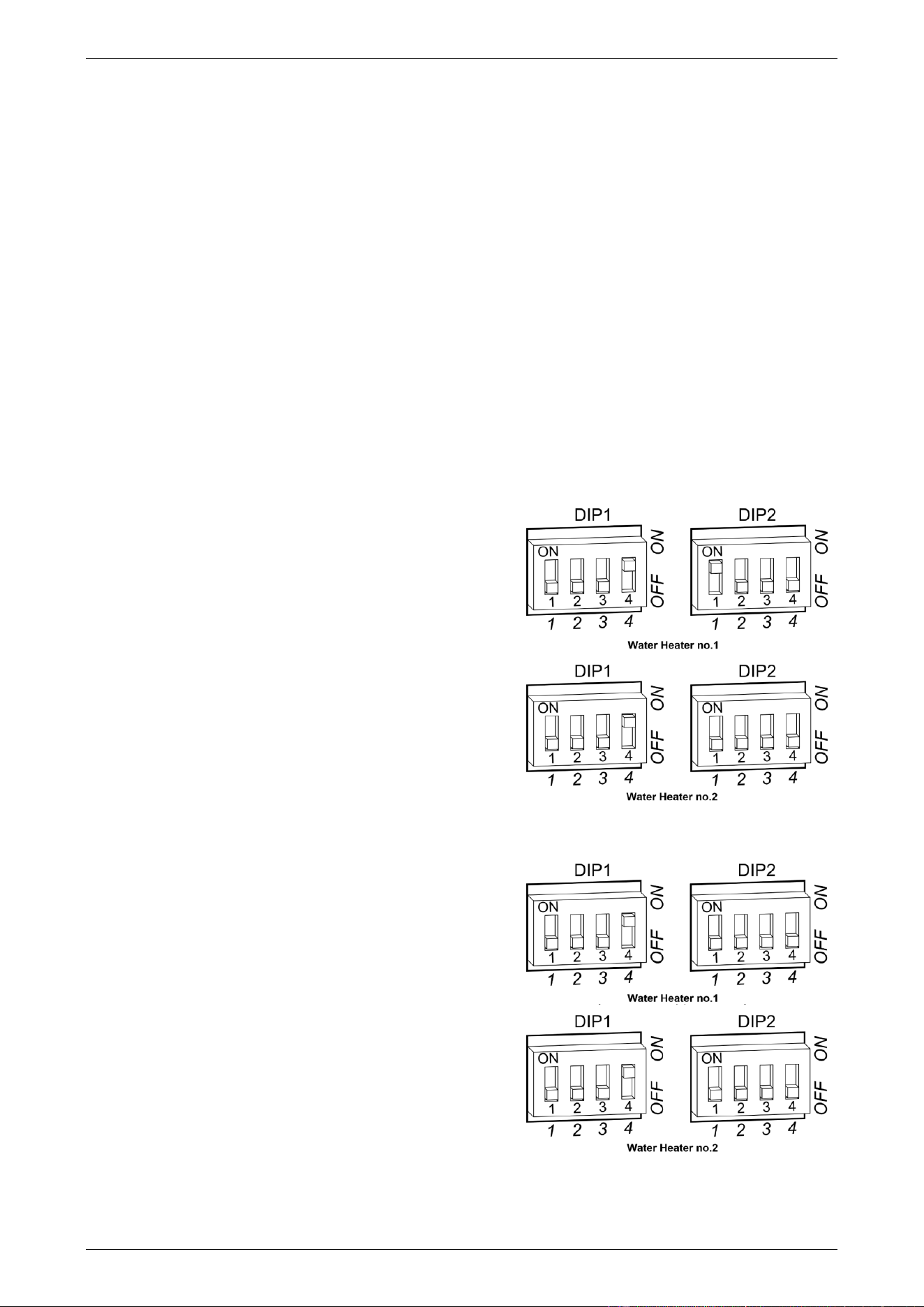
EZ LINK SYSTEM DUAL INSTALLATION
54
EZ LINK CABLE CONNECTION
The references in steps 5 to 9 are to the ‘Control Board with EZ Link Connection’ diagram on page 55. To
connect the EZ Link cable to the water heaters:
1. Close any hot taps and ensure the burners on both water heaters are not operating.
2. Switch off the electrical supply at the power outlet to each water heater.
3. Remove the screws holding the front panel to the jacket on each water heater.
4. Gently disengage the front panel and pull forward to remove from each water heater.
5. Carefully remove the plastic protective cover from in front of the PCB board from each water heater. This
is held in position with three holes in its top side and right side, engaging with three spigots in the PCB
support housing.
6. Connect one end of the EZ Link cable to the first water heater.
If a controller(s) is connected to one of the water heaters, then this is the ‘first’ or ‘master’ water heater.
▪ Draw the cable through the far-left cable grommet on the underside of the water heater.
▪ Plug the cable into the four pin connector located at the middle bottom of the Control Board (refer to
the Control Board diagram on page 55).
The connector will only fit one way.
▪ Press until the connector snaps into place.
▪ Secure the EZ Link cable with the clamp and screw
provided to the steel spigot adjacent to the cable
penetration and cable grommet at the bottom of the
water heater (refer to the Control Board diagram on
page 55).
7. Switch DIP SWITCH 4 to the on (up) position on the first
water heater (refer to the Control Board diagram).
Note: This dip switch is on the DIP 1 set of dip switches.
▪ If a temperature controller is not installed, then also
switch DIP SWITCH 1 of the DIP 2 set of dip
switches to the on (up) position on the first water
heater.
8. Connect the other end of the EZ Link cable to the second
water heater.
▪ Draw the cable through the far-left cable grommet
on the underside of the water heater.
▪ Plug the cable into the four pin connector located at
the middle bottom of the Control Board (refer to the
Control Board diagram).
The connector will only fit one way.
▪ Press until the connector snaps into place.
▪ Secure the EZ Link cable with the clamp and screw
provided to the steel spigot adjacent to the cable
penetration and cable grommet at the bottom of the
water heater (refer to the Control Board diagram)
9. Switch DIP SWITCH 4 to the on (up) position on the
second water heater (refer to the Control Board
diagram). Note: This dip switch is on the DIP 1 set of dip
switches.
dip switch settings
without temperature controller
dip switch settings
with temperature controller connected
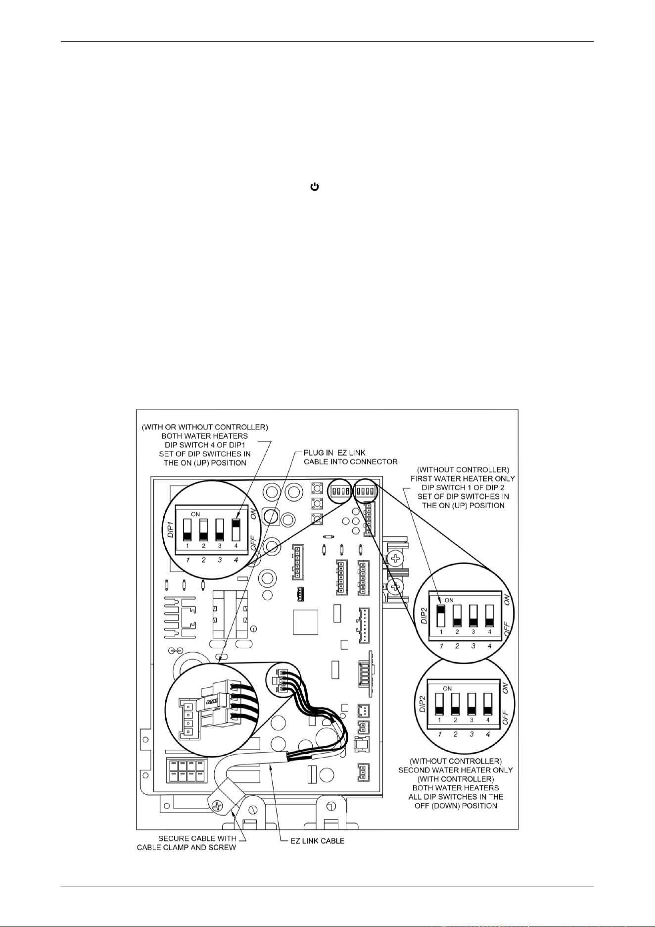
EZ LINK SYSTEM DUAL INSTALLATION
55
10. Carefully replace the plastic protective cover over the front of the PCB board to each water heater. Secure
in position by engaging the three spigots in the PCB support housing through the three holes in the
protective cover’s top side and right side.
11. Refit the front panel and screws to each water heater.
12. Check the main gas isolation valve and the isolation valves at the gas inlet to each water heater are fully
open.
13. Switch on the electrical supply at the power outlets to the water heaters.
14. Turn on the controller by pressing the on / off ( ) button, if one is installed.
The on / off operating light and the priority light will both glow.
15. Check to ensure the flow from each connected hot tap is sufficient to operate a water heater.
◼ Open each hot tap independently.
One of the water heaters will operate automatically.
Note: The minimum operating flow rate for each water heater is 1.5 litres per minute.
16. Increase the hot water flow by turning on multiple hot taps until both of the water heaters operate to ensure
the EZ Link system is working correctly.
17. Turn off the hot taps.
Refer to “Commissioning” on page 57 for details on completing the installation.
Control Board with EZ Link Connection
in use
priority
X 10L
88
°C
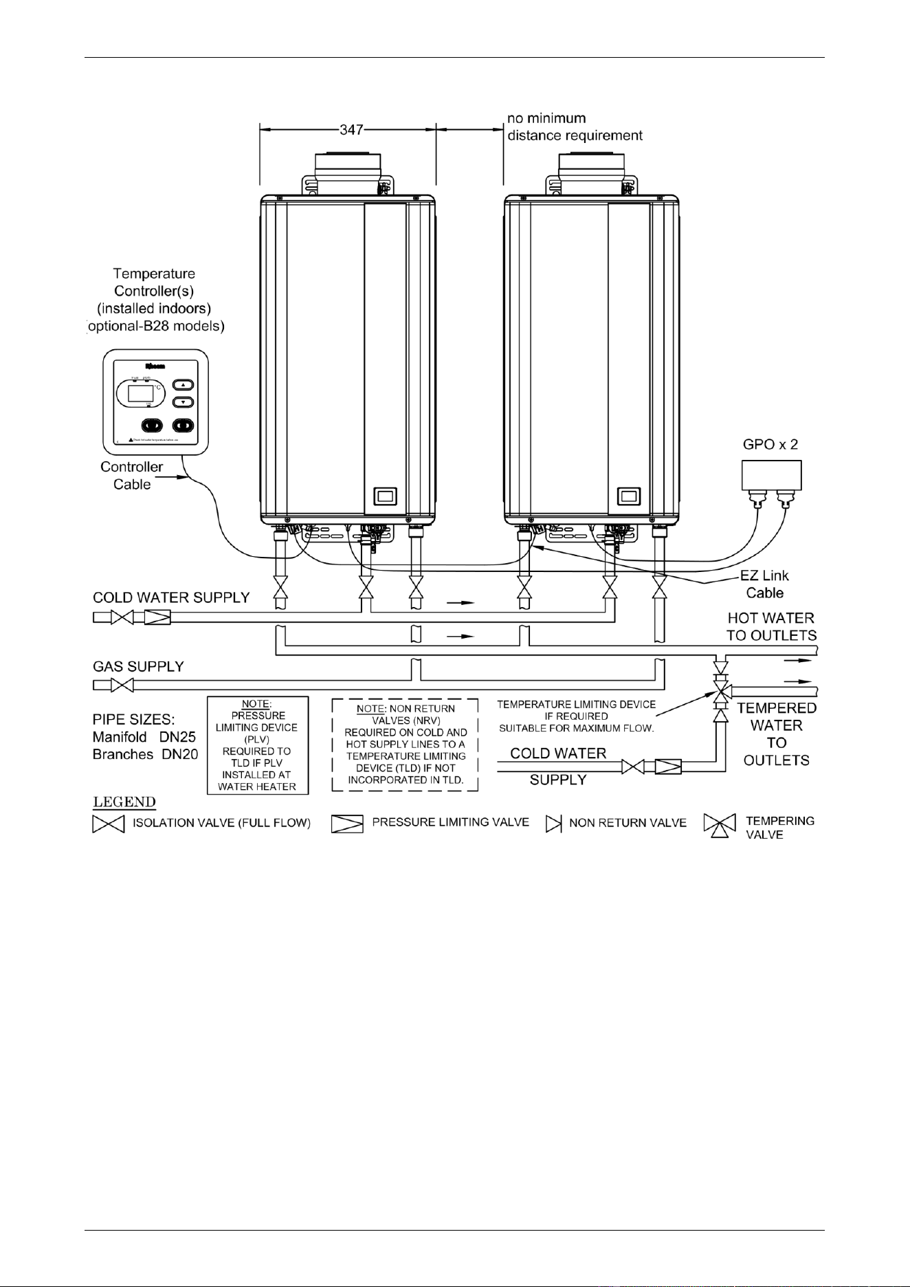
EZ LINK SYSTEM DUAL INSTALLATION
56
Typical Two Unit Manifold with EZ Link Connection

57
COMMISSIONING
All water heaters are tested and adjusted before dispatch from the factory, however further adjustments may
become necessary because of local conditions.
TO TURN ON THE WATER HEATER
• Open all of the hot taps in the house (don’t forget the shower).
• Open the cold water isolation valve fully at the inlet to the water heater.
Air will be forced out of the taps.
• Close each tap as water flows freely from it.
• Check the pipe work for leaks.
• Open the gas isolation valve fully.
• Check the gas pipe work for leaks.
• Plug in the water heater at the power outlet and switch on the electrical supply.
• Turn on a controller, if one is fitted, by pressing the on / off ( ) button.
The on / off operating light and the priority light will both glow.
• Open a hot tap.
The water heater will operate automatically.
• Check to ensure the flow from each connected hot tap is sufficient to operate the water heater.
The minimum operating flow rate for all models is 1.5 litres per minute.
• Check and if required adjust the preset outlet temperature setting of the water heater.
Refer to “Preset Outlet Temperature Setting” on page 61.
• Check and if required adjust the outlet temperature compensation adjustment on an 866 series water
heater.
Refer to “Outlet Temperature Compensation Adjustment” on page 63.
The automatic water governor incorporated in the water heater is not adjustable.
To complete the installation, it is necessary to check the gas supply pressure at the inlet to the water heater
(refer to “Gas Inlet Pressure” on page 57), the minimum test point pressure and the maximum test point
pressure (refer to “Burner Gas Pressure” on page 59).
Upon completion and testing of the installation, ensure the controller(s) is turned off (if fitted). Explain to the
householder or a responsible officer the functions and operation of the water heater and the controllers (if
fitted).
Warning: Upon completion of the installation and commissioning of the water heater, leave this guide with
the householder or a responsible officer. DO NOT leave this guide inside of the cover of the water heater, as
it may interfere with the safe operation of the water heater or ignite when the water heater is turned on.
GAS INLET PRESSURE
IMPORTANT - CHECK the gas supply pressure at the inlet to the water heater with the water heater and all
other gas burning appliances in the premises operating (burners alight). The minimum gas supply pressure is:
Natural Gas 1.13 kPa
If this minimum cannot be achieved, it may indicate the meter or the gas line to the water heater is undersized.
It is important to ensure that an adequate gas supply pressure is available to the water heater when other gas
burning appliances, on the same gas supply, are operating.
in use
priority
X 10L
88
°C
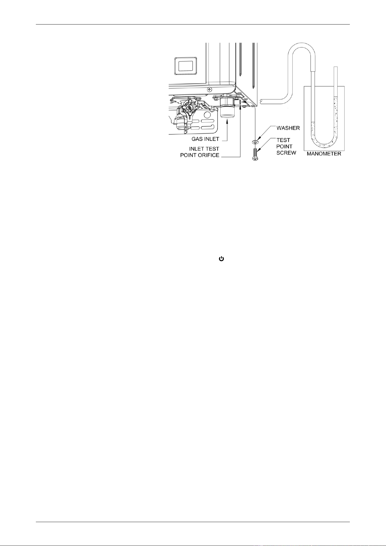
COMMISSIONING
58
Gas Inlet Test Point Pressure
To check the gas inlet pressure:
1. Close any hot taps and ensure the
burners are not operating.
2. Close the gas isolation valve at the gas
inlet to the water heater.
3. Locate the gas inlet test point on the
gas connection to the water heater.
▪ Remove the test point screw and
washer from the test point orifice.
▪ Connect the manometer.
4. Open the gas isolation valve fully at the
gas inlet to the water heater.
5. Observe the gas pressure reading on the manometer.
If the manometer reading is between the minimum and maximum inlet gas pressure ratings on the rating
label, no adjustment is required.
If the manometer reading is below the minimum inlet gas pressure rating on the rating label, then either
the gas pipe to the water heater is undersized and needs to be rectified or adjustment is required at the
gas regulator.
If the manometer reading is above the maximum inlet gas pressure ratings on the rating label, then
adjustment is required at the gas regulator.
6. Switch on the electrical supply at the power outlet to the water heater if it is not already switched on and
turn on a controller, if one is fitted, by pressing the on / off ( ) button.
7. Open a hot tap fully and ensure the burners are fully ignited.
It may be necessary to open a second tap.
8. Turn on all other gas burning appliances in the house which are on the same gas supply.
9. Observe the gas pressure reading on the manometer.
If the manometer reading is between the minimum and maximum inlet gas pressure ratings on the rating
label, no adjustment is required.
If the manometer reading is below the minimum inlet gas pressure rating on the rating label, then either
the gas pipe to the water heater is undersized and needs to be rectified or adjustment is required at the
gas regulator.
If the manometer reading is above the maximum inlet gas pressure ratings on the rating label, then
adjustment is required at the gas regulator.
10. Turn off the other gas burning appliances in the house.
11. If an adjustment was made during Step 9, repeat this procedure from Step 5.
12. Close the hot tap(s).
13. Close the gas isolation valve at the inlet to the water heater.
14. Remove the manometer and refit and tighten the test point screw and washer.
15. Open the gas isolation valve fully at the gas inlet to the water heater.
16. Open a hot tap again so the burners ignite.
17. Test for gas leaks.
18. Close the hot tap.
in use
priority
X 10L
88
°C
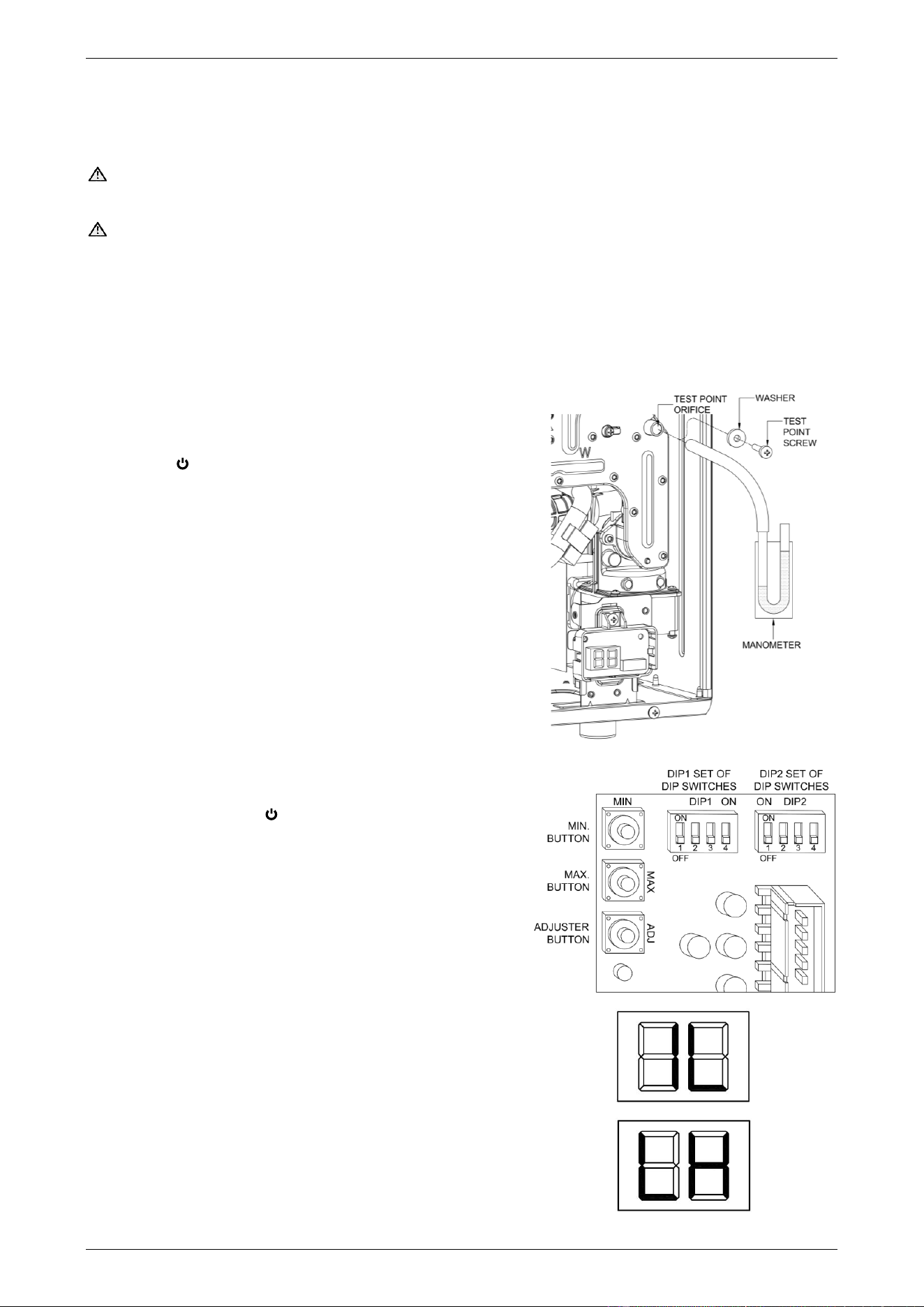
COMMISSIONING
59
BURNER GAS PRESSURE
It is necessary to check the burner gas pressure at both the minimum and maximum operational settings. To
check and if necessary adjust the operational gas pressures, the electrical supply to the water heater must be
switched on, the burners ignited and hot water must be flowing from a hot tap.
Warning: The removal of the front panel will expose 220 - 240 V a.c. wiring. Take care not to touch wiring
terminals.
Warning: This procedure will involve pressing the MIN, MAX and adjuster buttons. The pressing of these
buttons should only be performed with an insulated tool.
Note: If an 864 series model is installed as a gas booster for a solar water heater, then during this procedure
the temperature of the water entering the gas booster must be below 58°C. Otherwise the gas burners will not
ignite and the operational gas pressures cannot be measured.
Minimum burner test point gas pressure
Refer to the rating label on the water heater for the minimum burner test point gas pressure.
1. Close any hot taps and ensure the burners are not
operating.
2. Turn off the controller(s), if one is fitted, by pressing the
on / off ( ) button and switch off the electrical supply at
the power outlet to the water heater.
3. Remove the screws holding the front panel to the jacket.
4. Gently disengage the front panel and pull forward to
remove from the water heater.
5. Locate the burner pressure test point on the main burner
manifold.
◼ Remove the test point screw and washer from the test
point orifice.
◼ Connect the manometer.
6. Carefully remove the plastic protective cover from in front
of the PCB board. This is held in position with three holes
in its top side and right side, engaging with three spigots
in the PCB support housing.
7. Switch on the electrical supply at the power outlet to the
water heater and turn on a controller, if one is fitted, by
pressing the on / off ( ) button.
8. Open the gas isolation valve fully at the gas inlet to the
water heater, if not already open.
9. Open a hot tap slowly until the burners ignite.
10. Press and hold down the MIN button and observe the
reading on the manometer.
◼ “1L” is shown on the LED display.
11. Release the MIN button.
If the manometer reading observed in step 10 agrees with
the rating label, no further adjustment is required.
12. To adjust, press and hold the adjuster button.
◼ “LH” is shown on the LED display.
Note: The adjuster button must be held down
continuously through steps 12 to 14.
13. Press and hold the MIN button and observe the reading
on the manometer.
◼ The manometer reading will change as the test point
gas pressure adjusts.
in use
priority
X 10L
88
°C
in use
priority
X 10L
88
°C
Step 5
Step 10
Step 12
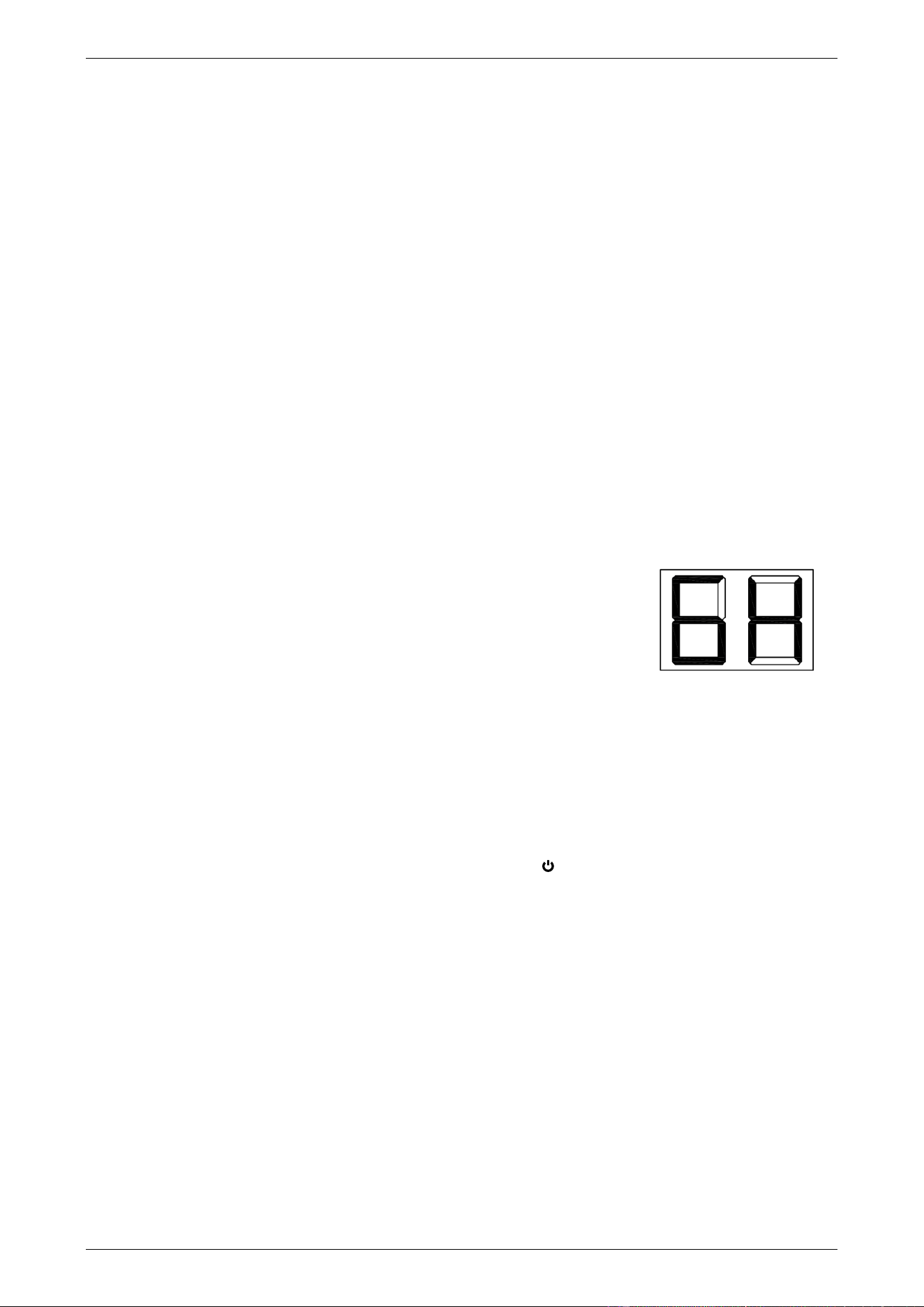
COMMISSIONING
60
Note: While the MIN button is pressed, the gas pressure will at first increase then decrease, cycling
between an upper gas pressure limit (59 on the LED display) and a lower gas pressure limit (01 on the
LED display).
14. Release the MIN button when the reading on the manometer agrees with the rating label.
15. Release the adjuster button.
Notes
• If the burners extinguish and error code 11 or 12 starts to flash on the LED display:
▪ release the MIN and adjuster buttons
▪ close the hot tap
▪ clear the error code (refer to “Clearing Error Code” on page 60)
▪ recommence the procedure from Step 9.
• If the adjuster button is released before Step 14, clear any error code (if displayed) and recommence the
procedure from Step 9.
Maximum burner test point gas pressure
Refer to the rating label on the water heater for the maximum burner test point gas pressure.
Follow Steps 9 to 15 of the “Minimum test point gas pressure” procedure on page 59, but open the hot tap fully
and use the MAX button instead of the MIN button. It may be necessary to open two or three hot taps fully,
depending upon the model of water heater and the incoming cold water temperature.
Notes
• In Step 10, “6H” (B28 models) will be shown on the LED display.
• In Step 13, while the MAX button is pressed, the gas pressure will at first
increase then decrease, cycling between an upper gas pressure limit (39
on the LED display) and a lower gas pressure limit (01 on the LED display).
After setting the minimum and maximum test point gas pressures:
• Close the hot tap.
• Remove the manometer and refit and tighten the test point screw and washer.
• Open a hot tap again so the burners ignite.
• Test for gas leaks.
• Close the hot tap.
• Turn off the controller, if one is fitted, by pressing the on / off ( ) button.
• Switch off the electrical supply at the power outlet to the water heater.
• Carefully replace the plastic protective cover over the front of the PCB board. Secure in position by
engaging the three spigots in the PCB support housing through the three holes in the protective cover’s
top side and right side.
• Refit the front panel and screws to the water heater.
Clearing Error Code
If an error code does appear on the LED display during the commissioning process, it will be necessary to
clear the error in order to complete the installation.
To clear an error code:
• switch off the electrical supply at the power outlet to the water heater.
• check the gas isolation valve at the gas inlet to the water heater is fully open.
• wait five (5) minutes.
• switch on the electrical supply at the power outlet to the water heater.
in use
priority
X 10L
88
°C
Step 10
max burner test point gas pressure

COMMISSIONING
61
PRESET OUTLET TEMPERATURE SETTING
The factory preset outlet temperature setting of the water heater is:
• 864 series 60°C
• 866 series 50°C
If a temperature controller is connected to the water heater, this will override the preset outlet temperature
setting and the maximum temperature setting will be:
Maximum Outlet Temperature
864 series
866 series
Kitchen controller connected
60°C
50°C
Bathroom controller only connected
50°C
50°C
It is usually not necessary to adjust the factory preset outlet temperature setting of the water heater, unless
the customer has a particular requirement for this to be done or it is to be installed as an in-series gas booster
to a solar water heater.
Refer to “To Check or Adjust the Preset Outlet Temperature Setting” on page 61 to check or if required to
adjust the preset outlet temperature setting of the water heater.
Gas Booster for a Solar Water Heater
Note: Australian Standard AS 3498 requires that a water heater provides the means to inhibit the growth of
Legionella bacteria in potable water. When the 864 series water heater is used as an in-series booster for a
solar water heater it can satisfy the AS 3498 requirements provided it is energised, the booster preset outlet
temperature setting is at least 70°C, and that a remote temperature controller is not used.
It will be necessary to check and if required to adjust the preset outlet temperature setting of the continuous
flow water heater when:
• it is installed as an in-series gas booster to a solar water heater
• it is an existing continuous flow water heater and a solar water heater is then installed.
Notes
• Consideration must be given to the delivery temperature to any ablution and public areas such as a
bathroom, ensuite or public amenities. Refer to “Hot Water Delivery” on page 23 and to “Schematics of
Two Temperature Zones Using A Temperature Limiting Device” on page 24.
• The 866 series water heater, marked “THIS APPLIANCE DELIVERS WATER NOT EXCEEDING 50°C IN
ACCORDANCE WITH AS 3498” on the front panel, must not be installed as an in-series gas booster to
a solar water heater, as water temperature greater than 50°C can be delivered from the water heater
contravening its compliance to AS 3498.
TO CHECK OR ADJUST THE PRESET OUTLET TEMPERATURE SETTING
The temperature settings will be displayed on the LED display. The preset outlet temperature settings are:
• 864 series 40°C, 42°C, 45°C, 50°C, 55°C, 60°C, 65°C, 70°C, 75°C
• 866 series 40°C, 42°C, 45°C, 50°C
It is necessary to have the electrical supply to the water heater switched on during stages of checking or
adjusting the preset outlet temperature setting procedure.
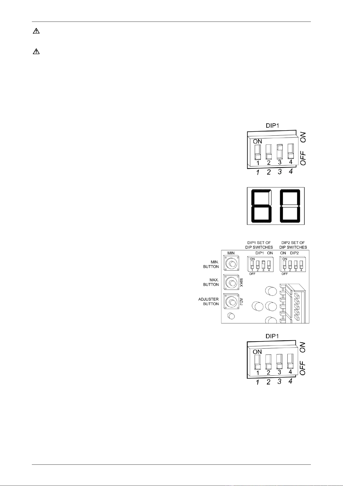
COMMISSIONING
62
Warning: The removal of the front panel will expose 220 - 240 V a.c. wiring. Take care not to touch wiring
terminals. The adjustment must be carried out by a qualified person.
Warning: This procedure will involve the adjustment of dip switches and may involve the pressing of the
MIN and MAX buttons. Adjustment of a dip switch or the pressing of the MIN and MAX buttons should only be
made with an insulated tool.
To check or adjust the preset outlet temperature setting:
1. Switch off the electrical supply at the power outlet to the water heater.
2. Remove the screws holding the front panel to the jacket.
3. Gently disengage the front panel and pull forward to remove from the water heater.
4. Close the cold water isolation valve at the inlet to the water heater.
5. Carefully remove the plastic protective cover from in front of the PCB board.
This is held in position with three holes in its top side and right side, engaging
with three spigots in the PCB support housing.
6. Switch on the electrical supply at the power outlet to the water heater.
Note: Wait ten (10) seconds for the electronic system to initialise.
7. Switch dip switch 3 to the on (up) position on the DIP 1 set of DIP switches
on the I.C. Board.
The current preset outlet temperature setting will show on the LED display.
If the temperature displayed on the LED display is the desired preset outlet
temperature setting, then proceed to step 9, as no further adjustment is
necessary.
8. Press the MAX button to increase or the MIN button to
decrease the preset outlet temperature setting.
Each press of the MAX or MIN button will increase or
decrease the preset temperature by one increment.
The MAX and MIN buttons are located to the left of the
DIP 1 and DIP 2 set of DIP switches.
864 series
The increments are 40°C, 42°C, 45°C, 50°C, 55°C, 60°C,
65°C, 70°C, 75°C.
866 series
The increments are 40°C, 42°C, 45°C, 50°C.
9. Switch dip switch 3 to the off (down) position.
The LED display will go blank.
Note: Wait ten (10) seconds for the setting to be saved. The preset outlet
temperature setting is now set.
10. Switch off the electrical supply at the power outlet to the water heater.
11. Carefully replace the plastic protective cover over the front of the PCB board.
▪ Secure in position by engaging the three spigots in the PCB support housing through the three holes
in the protective cover’s top side and right side.
12. Refit the front panel and screws to the water heater.
13. Open the cold water isolation valve fully at the inlet to the water heater.
14. Switch on the electrical supply at the power outlet to the water heater.
Step 7
Step 8
Step 9
COMMISSIONING
63
OUTLET TEMPERATURE COMPENSATION ADJUSTMENT
The outlet temperature compensation adjustment function is only applicable to:
• 866 series B28 water heaters
The maximum outlet temperature may be adjusted to compensate for temperature losses in the pipe work
between the water heater outlet and fixtures used primarily for personal hygiene.
This procedure cannot be conducted on an 864 series water heater.
Warnings
• After adjustment, the water temperature from the first tap in the hot water pipe work used primarily for
personal hygiene after the water heater, such as in a bathroom or ensuite, MUST NOT exceed:
▪ The temperature displayed on a temperature controller connected to the water heater, or
▪ 50°C if a temperature controller is not connected to an 866 series water heater.
• If there is a tap, such as a kitchen or laundry tap, in the hot water pipe work between the water heater and
the first tap used primarily for personal hygiene, then it is possible for a water temperature to be delivered
from that tap of up to 2°C higher than the setting shown on the controller.
Warnings
• It is necessary to have the electrical supply to the water heater switched on during stages of the outlet
temperature compensation adjustment procedure.
• The removal of the front panel will expose 220 - 240 V a.c. wiring. Take care not to touch wiring terminals.
The adjustment must be carried out by a qualified person.
• This procedure will involve the adjustment of dip switches and may involve the pressing of the MAX and
MIN buttons. Adjustment of a dip switch or the pressing of the MAX and MIN buttons should only be made
with an insulated tool.
Before Commencing the Procedure
This procedure cannot be conducted:
• If the preset outlet temperature is set below 50°C. The preset outlet temperature setting of the 866 series
water heater must be set to 50°C. Refer to “To Check or Adjust the Preset Outlet Temperature Setting”
on page 61.
• With a temperature controller connected to the water heater.
▪ A temperature controller(s) connected to the water heater must be disconnected prior to the
commencement of this procedure. Refer to Step 10 of the procedure on page 64.
• With an EZ Link system set up on the water heaters.
▪ The EZ Link cable does not need to be disconnected.
▪ The DIP switches need to be reset to the off (down) position on both water heaters prior to the
commencement of this procedure. Refer to Step 11 of the procedure on page 64.
▪ The Outlet Temperature Compensation Adjustment procedure has to be performed individually on
both water heaters.
▪ Whilst the procedure is being conducted on one water heater, the other water heater has to be
isolated by turning off the cold water isolation valve to the water heater.
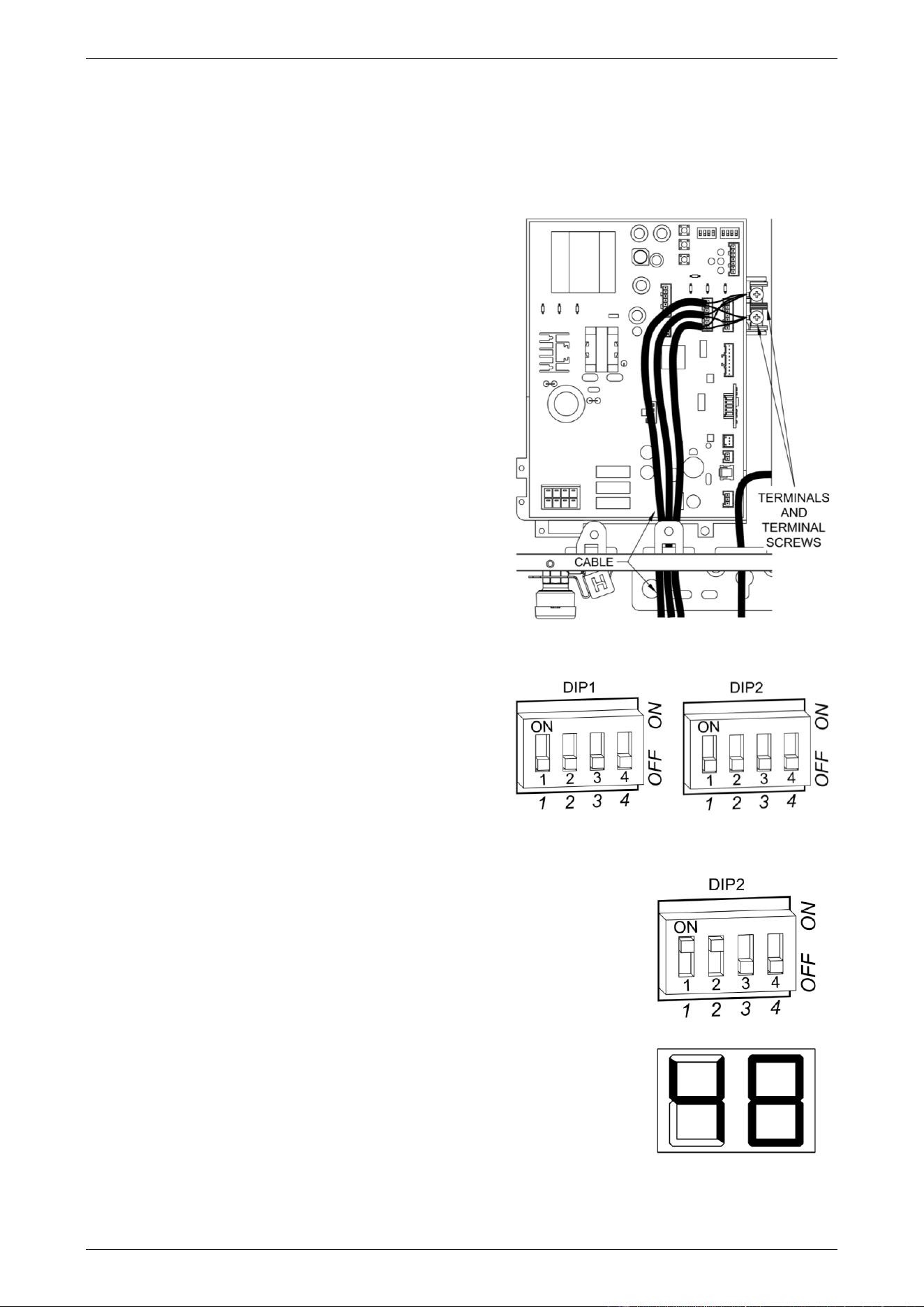
COMMISSIONING
64
Outlet Temperature Adjustment
To adjust the outlet temperature:
1. Switch on the electrical supply at the power outlet to the water heater.
2. Locate the first hot tap in the hot water pipe work after the water heater used primarily for personal hygiene.
3. Turn on the hot tap.
4. Using a thermometer, measure the temperature of the
water from the tap, until the temperature stops
increasing.
If the water temperature is below 50°C, the maximum
outlet temperature of the water heater can be adjusted
upwards.
5. Turn off the hot tap.
6. Switch off the electrical supply at the power outlet to the
water heater.
7. Remove the screws holding the front panel to the
jacket.
8. Gently disengage the front panel and pull forward to
remove from the water heater.
9. Carefully remove the plastic protective cover from in
front of the PCB board, if it was not already removed
during the disconnection of the wires of temperature
controllers. This is held in position with three holes in
its top side and right side, engaging with three spigots
in the PCB support housing.
10. If a temperature controller(s) is connected, the cable
terminal lugs must be disconnected from the terminals:
▪ Loosen the terminal screws to release the cable
lugs.
▪ Withdraw the cable lugs, ensuring they are well
clear of the terminals and other components.
11. If the water heater is part of an EZ Link system
installation, reset the DIP switches to the off (down)
position.
12. Switch on the electrical supply at the power outlet to the water heater.
Note: Wait ten (10) seconds for the electronic system to initialise.
13. Switch dip switches 1 and 2 to the on (up) position on the DIP 2 set of
DIP switches on the I.C. Board.
The temperature setting of ‘48’ will show on the LED display, if this has not
previously been adjusted.
Step 13
Step 10 – Disconnect the temperature controller
cable(s) if a temperature controller is fitted.
Step 11 – Reset DIP switches to off if EZ Link installed.
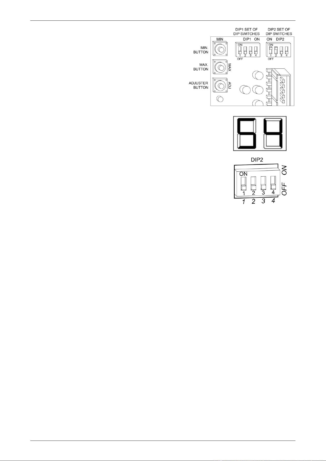
COMMISSIONING
65
14. Press the MAX button once to increase the outlet
temperature setting to the next increment.
The MAX button is located to the left of the DIP 1 and
DIP 2 set of DIP switches and in between the MIN (top)
and Adjuster (bottom) buttons.
Each press of the MAX button will increase the
temperature setting by one increment.
The outlet temperature setting will show on the LED
display.
The outlet temperature setting increments above 48°C
are:
▪ 50°C, 51°C, 52°C, 53°C, 54°C.
15. Switch dip switches 1 and 2 to the off (down) position on the DIP 2 set of
DIP switches on the I.C. Board.
The LED display will go blank.
Note: Wait ten (10) seconds for the setting to be saved.
16. Check the water temperature at the hot tap by repeating steps 2 to 5.
17. Further adjustment – Increase: If the water temperature is still below 50°C
and requires to be increased, repeat steps 13, 14 and 15, followed by
steps 2 to 5 until an acceptable water temperature not exceeding 50°C is
measured at the same hot tap.
18. Further adjustment – Decrease: If the water temperature exceeds 50°C,
then to decrease the temperature;
◼ switch dip switches 1 and 2 to the on (up) position on the DIP 2 set of DIP switches on the I.C. Board.
The outlet temperature setting will show on the LED display.
◼ press the MIN button once to decrease the outlet temperature setting to the next increment.
Each press of the MIN button will decrease the outlet temperature by one increment.
The MIN (top) button is located to the left of the DIP 1 and DIP 2 set of DIP switches and above the
MAX (middle) button.
◼ Switch dip switches 1 and 2 to the off (down) position on the DIP 2 set of DIP switches on the I.C.
Board.
The LED display will go blank.
Note: Wait ten (10) seconds for the setting to be saved.
▪ repeat steps 2 to 5 to confirm the water temperature does not exceed 50°C.
19. Switch off the electrical supply at the power outlet to the water heater.
20. Reconnect the controller cables (if a temperature controller is fitted).
▪ Reposition the cable lugs onto the terminals, ensuring they are well clear of other components.
▪ Tighten the terminal screws to secure the cable lugs.
21. Reset the DIP switches if the water heater is part of an EZ Link system installation, by following steps 7
and 9 of the procedure “EZ Link Cable Connection” on page 54.
22. Carefully replace the plastic protective cover over the front of the PCB board. Secure in position by
engaging the three spigots in the PCB support housing through the three holes in the protective cover’s
top side and right side.
23. Refit the front panel and screws to the water heater.
24. Switch on the electrical supply at the power outlet to the water heater.
Step 14
Step 15
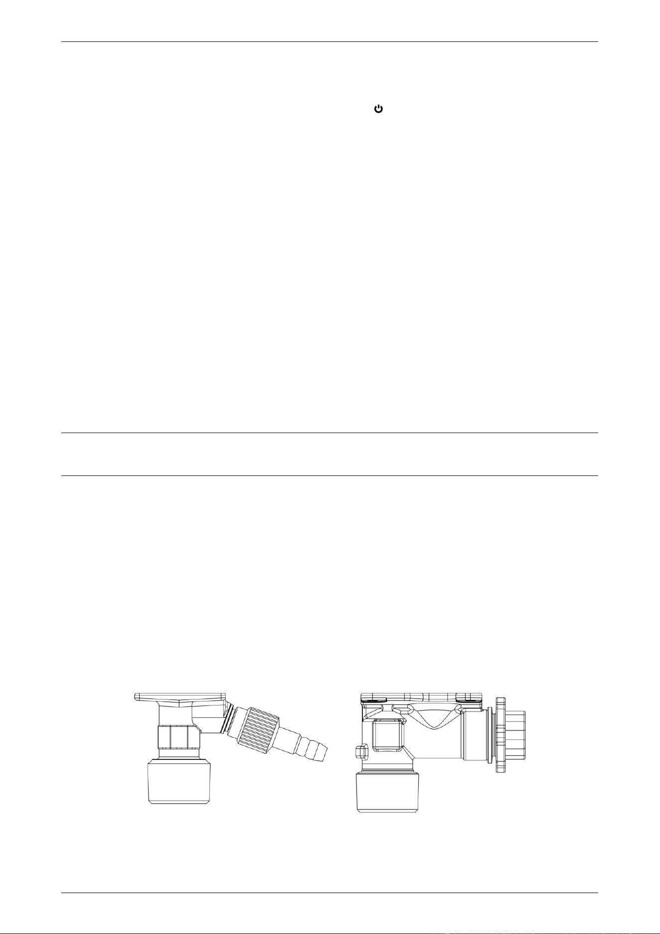
COMMISSIONING
66
TO TURN OFF THE WATER HEATER
If it is necessary to turn off the water heater on completion of the installation, such as on a building site or
where the premises is vacant, then:
• Turn off the controllers(s) (if fitted) by pressing the on / off ( ) button.
The on / off operating light will go out and the priority light, if it is on, will go out.
• Switch off the electrical supply at the power outlet to the water heater (refer to note below).
• Close the gas isolation valve at the inlet to the water heater.
• Close the cold water isolation valve at the inlet to the water heater.
• Drain the water heater if there is a risk of freezing conditions occurring (refer to “Draining The Water
Heater” on page 66).
Notes
• The frost protection system will be rendered inoperable if electrical power is not available at the water
heater.
• Damage caused by freezing due to the unavailability of power at the water heater is not covered by the
Rheem warranty (refer to “Terms of the Rheem Warranty” on page 4).
• If the power has been switched off to the water heater and there is a risk of freezing, then it is necessary
to drain the water heater (refer to “Draining the Water Heater” on page 66).
DRAINING THE WATER HEATER
To drain the water heater:
• Turn off the water heater (refer to “Turn Off The Water Heater” on page 66).
• Open a hot tap (preferably the shower outlet).
• Unscrew the two drain plugs, one each at the cold water inlet and hot water outlet (864 series model) or
50°C limited outlet (866 series model), on the underside of the water heater.
Water will drain from the water heater.
• When water stops flowing from the water heater, close the hot tap.
Note: It is recommended not to screw the drain plugs back in, until the water heater is to be turned on again.
HOT WATER OUTLET COLD WATER INLET
in use
priority
X 10L
88
°C

67
This page is intentionally blank.

Revision Date: 2024 April (41-41377-00) 122357 Rev-01
68
