7386805 (Rev. A 10/6/20)
ELECTRONIC CONTROL BOARD (PWA) REPLACEMENT
Display
RECHARGE
button
UP button
SELECT
button
DOWN
button
1. Unplug the water softener’s power supply from electrical power.
2. Remove the top cover and salt lid to expose the valve.
3. Unsnap the faceplate from its support to expose the Electronic
Control Board.
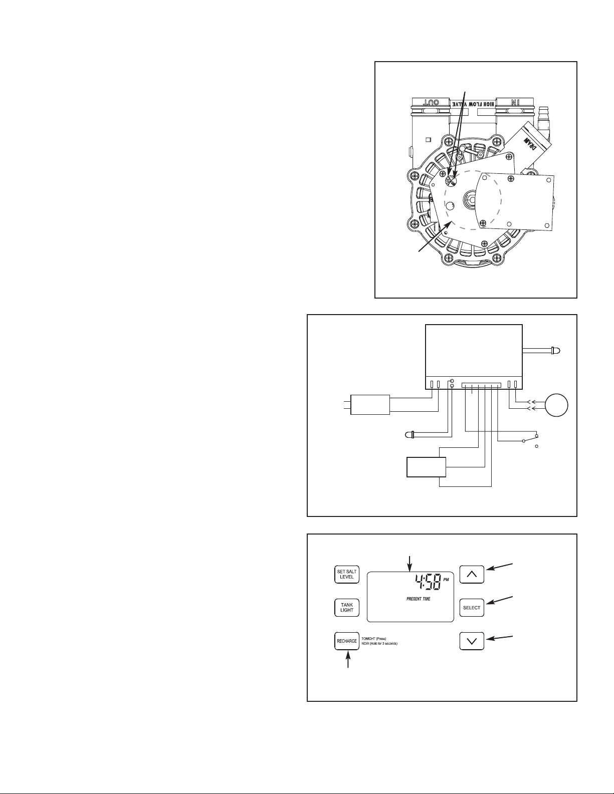
4. Unplug the wiring connections from the back of the old Electronic
Control Board (See Figure 2) and remove the old board’s status light
from its holder in the faceplate.
5. Carefully remove the old board by unsnapping it from its retainer tabs.
6. Carefully snap the new Electronic Control Board into the retainer tabs.
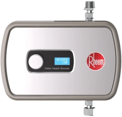
IMPORTANT: BE SURE THE VALVE CAM INDICATES “SERVICE”
P
OSITION (See Figure 1) WHEN REPLACING THE ELECTRONIC
CONTROL BOARD (PWA), TO ASSURE BOTH VALVE AND PWA
A
RE ORIENTED, OR TIMED, TO THE SAME CYCLE. If the valve is
not in Service position, see step 12 below.
NOTE: When installing the electronic control board (PWA) on the face-
p
late, use care not to twist the circuit board, or force it onto the
mounting pegs. Twisting could damage the printed circuits, or break the
display glass.
7. Reconnect the wiring to the new board (See Figure
2) and insert the new board’s status light into the
holder in the faceplate.
8. Snap the faceplate back into its holder, being careful
not to pinch any wires.
9. Plug the power supply into the electrical outlet.
A model code (rH42) and a software version number
(example: J4.0) briefly appear in the faceplate
display. Then the words “PRESENT TIME” appear
and “12:00 PM” begins to flash.
10. Press the
r UP and s DOWN buttons to set the
present time. Up moves the display ahead; down
sets the time back.
NOTE: Press buttons and quickly release to slowly
advance the display. Hold the buttons down for
fast advance.
11. Press the SELECT button, and continue program-
ming hardness, recharge start time, salt type, and
salt level. For details, consult your owner’s
manual. When you have finished programming the
controller, the time appears on the display, but is
not flashing.
12. If the valve is not in Service position, press the
RECHARGE button and hold for 3 seconds to start
a recharge cycle. The display will flash “RECHARGE
NOW”. In about 2 hours the recharge cycle will be
complete and the valve and electronic control
board will be properly oriented together.
NOTE: To save time, use the manual advance proce-
dures to properly time and check operation.
See “Troubleshooting” in the owner’s manual.
Figure 3
P
osition markers
(valve in service)
CAM
MOTOR
Figure 1
Figure 2
Back of Electronic
Controller (PWA)
Valve
Motor
Pwr.
In
Motor
Tank
Light
Pos. /
Turbine
120V
AC
60 Hz
Power
Supply
24V DC
Tank Light
Turbine
Sensor
OUT
GND
+5
C
NC
NO
Position
Switch
Status
Light