Loading ...
Loading ...
Loading ...
5 Product Introduction
5.2 Panel Introduction
5.2.1 Panel Function
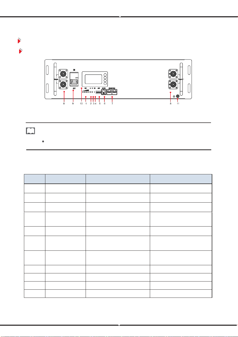
Figure 5-2 VT48100E Front Panel
NOTE
VT48100E ESS series panel functions take VT48100E as an example.
The interface definition as below table:
Table 5-1 Operation Panel Interface Definition
No. Name Description Remark
1
SOC
State of capacity
Details shows in table5-3
2
ALM
Alarm light
Details shows in table5-4
3
RUN
Run state of battery
Details shows in table5-4
4 RESET Reset switch
Restart battery and recover
some certain alarms status
5
ADD
Dip switch
Address range 0~15
6
RJ-11
RJ-11 interface for
firmware update
Used only for professional
maintenance
7
RJ-45
2*RJ-45 interface for
RS485/CAN communication
Details shows in table5-6
8
Battery Output
Power terminal
-
9 Switch Power switch -
10 LCD Liquid Crystal Display Display battery information
11
GND
Module ground connection
-
Loading ...
Loading ...
Loading ...