Loading ...
Loading ...
Loading ...
6 Installation
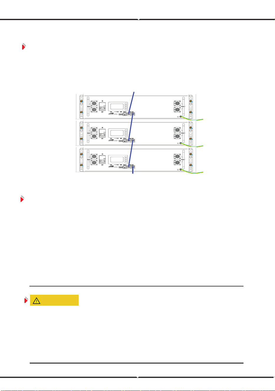
6.4.3 120Ω Resistor Connection
To ensure stable CAN communication with the external device/Inverter when
batteries are used in parallel, please take out a 120Ω resistor from the ‘Battery Kit’
and insert it into the RJ45 port of the battery that communicates farthest with the
external device/Inverter.
Figure 6-6 Connect 120Ω Resistor
6.5 Set Dial Address
Assign addresses to battery packs by dialing the dialing keys of the dialing
switch. DIP switch address please refer to“Table 5-5 Correspondence between BMS
and DIP switch”.
A. When the battery and the external device use the CAN communication
mode, the battery connected to the external device is set to 0, and the
other packs are set to 1/2/3 in sequence.
B. When the battery and the external device use the RS485 communication
mode, the battery connected to the external device is set to 1, and the
other packs are set to 2/3/4 in sequence.
ATTENTION
Before connecting cables, make sure that the bus-bars at the user end are in a
power-off state.
Pay attention to the polarity of the battery pack.
Communication cables and power cables must be laid separately.
Connect the negative power cables of all battery packs first, and then connect the
positive power cables of the battery packs.
120Ω
external device
Loading ...
Loading ...
Loading ...