Loading ...
Loading ...
Loading ...
5 Product Introduction
NOTE
The position or terminal block of the above-mentioned panel
interfaces is different for different VT48100E ESS series products. Please refer to
the corresponding product datasheet.
5.2.2 Indicator Description
There are 6 indicators on the operation panel, divided into three categories: 4
green SOC Indicators, 1 red alarm Indicator and 1 green run indicator.
Table 5-2 Indicators Flash Mode
Flash mode ON OFF Common name
Flash Mode 1 0.25 s 3.75 s /
Flash Mode 2 0.5 s 0.5 s Slow Flash
Flash Mode 3 0.5 s 1.5 s /
Flash Mode 4 0.25 s 0.25 s Strobe
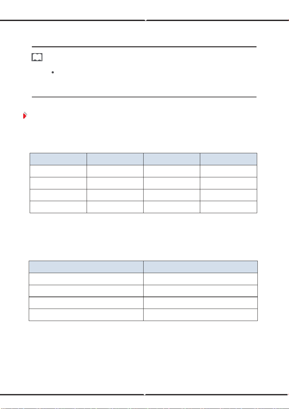
The power indicator is used to identify the current capacity status of the battery.
The number of flashing indicators corresponds to different remaining capacity. The
specific meaning is shown in the following table.
Table 5-3 SOC Indicator Definition
Number of Indicator
Remaining Capacity Range
1 indicator on 0%<SOC≤25%
2 indicators on 25%<SOC≤50%
3 indicators on 50%<SOC≤75%
4 indicators on 75%<SOC≤100%
Loading ...
Loading ...
Loading ...