
Loading ...
Loading ...
Loading ...
5 Product Introduction
The corresponding relationship between battery operation status and indicator
operation status is shown in the following table.
Table 5-4 Battery Status and Indicator Operation Mode
Battery
S
tatus
Normal/
Abnormal
RUN
ALM
SOC Indicators
Description
- - ● ● ● ● ● ● -
Power off/
Sleep
OFF
OFF
OFF
OFF
OFF
OFF
-
Standby
Normal
Flash 1
OFF
According to SOC
Flash mode
shown
in Table 5-2
Charge Normal Flash 2 OFF According to SOC -
Discharge Normal ON OFF According to SOC -
Alarm
Abnormal
According to the
state of charge
and discharge
Flash 2
According to SOC
Recoverable
Error Abnormal OFF ON OFF -
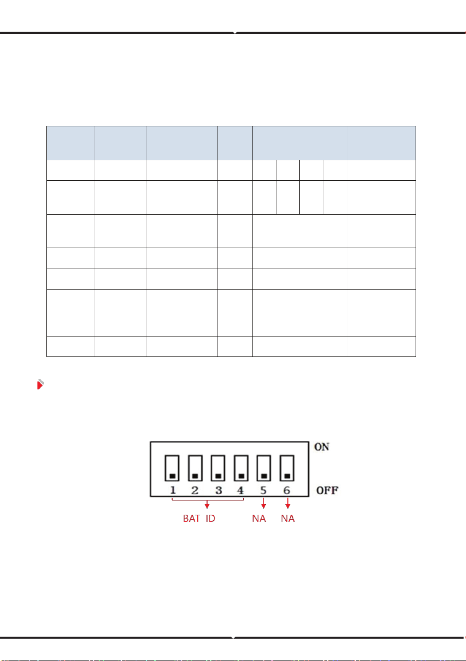
5.2.3 DIP Address
Please assign an address to the battery BMS through the DIP switch to
communicate with the battery.
Figure 5-3 DIP switch
Loading ...
Loading ...
Loading ...