Loading ...
Loading ...
Loading ...

2052R/2062R/2000T
Users Manual
14
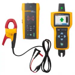
Connect the Transmitter
The Transmitter generates a signal on a wire which creates an electromagnetic field around
the wire. The Receiver detects the electromagnetic field to trace the wire.
With the Transmitter connected to two adjacent wires on the same circuit, the signal travels in
one direction through the first wire and returns in the opposite direction through the second
wire. This causes the creation of two electromagnetic fields around each wire with opposite
direction. The opposite fields partially or completely cancel each other out which makes it
difficult, if not impossible, to trace the signal.
Test Lead Connection
To connect the Transmitter to a wire with test leads:
1. For most applications, connect the red and green test leads directly to the Transmitter. The
polarity does not matter.
2. Connect the red test lead to the hot wire on the load-side of the circuit.
Note
For all applications, always connect the Transmitter on what would be the load-side of
an energized circuit whether or not the circuit is energized or de-energized.
3. Determine which type of circuit the wire to trace is on:
Not connected to a GFI device or an RCD
Connected to a GFI outlet
Connected to a GFI breaker
Connected to an RCD
4. To trace a wire on a circuit not connected to a GFI device or an RCD, connect the green test
lead to a separate ground such as a metal water pipe, a metal grounded structure of the
building, a grounded screwdriver, or a grounded stake.
With the Transmitter connected to a ground wire on a different circuit than the hot wire, the
Receiver can detect the signal only if the wires on both circuits are connected correctly.
The best practice is to connect to a separate ground.
Outlet and breaker types vary. Figure 2 shows a few examples of outlet and breaker type
connections.
1.888.610.7664 sales@GlobalTestSupply.com
Fluke-Direct.com
Loading ...
Loading ...
Loading ...