
2052R/2062R
Wire Tracer Receiver
2000T
Wire Tracer Transmitter
Users Manual
2/2023 (English)
©2023 Fluke Corporation. All rights reserved.
Specifications are subject to change without notice.
All Product names are trademarks of their respective companies.
1.888.610.7664 sales@GlobalTestSupply.com
Fluke-Direct.com

LIMITED WARRANTY AND LIMITATION OF LIABILITY
Each Fluke product is warranted to be free from defects in material and workmanship under
normal use and service. The warranty period is 1 year and begins on the date of shipment. Parts,
product repairs, and services are warranted for 90 days. This warranty extends only to the
original buyer or end-user customer of a Fluke authorized reseller, and does not apply to fuses,
disposable batteries, or to any product which, in Fluke's opinion, has been misused, altered,
neglected, contaminated, or damaged by accident or abnormal conditions of operation or
handling. Fluke warrants that software will operate substantially in accordance with its functional
specifications for 90 days and that it has been properly recorded on non-defective media. Fluke
does not warrant that software will be error free or operate without interruption.
Fluke authorized resellers shall extend this warranty on new and unused products to end-user
customers only but have no authority to extend a greater or different warranty on behalf of
Fluke. Warranty support is available only if product is purchased through a Fluke authorized
sales outlet or Buyer has paid the applicable international price. Fluke reserves the right to
invoice Buyer for importation costs of repair/replacement parts when product purchased in one
country is submitted for repair in another country.
Fluke's warranty obligation is limited, at Fluke's option, to refund of the purchase price, free of
charge repair, or replacement of a defective product which is returned to a Fluke authorized
service center within the warranty period.
To obtain warranty service, contact your nearest authorized service center to obtain return
authorization information, then send the product to that service center, with a description of the
difficulty, postage and insurance prepaid (FOB Destination). Fluke assumes no risk for damage
in transit. Following warranty repair, the product will be returned to Buyer, transportation
prepaid (FOB Destination). If Fluke determines that failure was caused by neglect, misuse,
contamination, alteration, accident, or abnormal condition of operation or handling, including
overvoltage failures caused by use outside the product’s specified rating, or normal wear and
tear of mechanical components, Fluke will provide an estimate of repair costs and obtain
authorization before commencing the work. Following repair, the product will be returned to the
Buyer transportation prepaid and the Buyer will be billed for the repair and return
transportation charges (FOB Shipping Point).
THIS WARRANTY IS BUYER'S SOLE AND EXCLUSIVE REMEDY AND IS IN LIEU OF ALL OTHER
WARRANTIES, EXPRESS OR IMPLIED, INCLUDING BUT NOT LIMITED TO ANY IMPLIED
WARRANTY OF MERCHANTABILITY OR FITNESS FOR A PARTICULAR PURPOSE. FLUKE SHALL
NOT BE LIABLE FOR ANY SPECIAL, INDIRECT, INCIDENTAL OR CONSEQUENTIAL DAMAGES OR
LOSSES, INCLUDING LOSS OF DATA, ARISING FROM ANY CAUSE OR THEORY.
Since some countries or states do not allow limitation of the term of an implied warranty, or
exclusion or limitation of incidental or consequential damages, the limitations and exclusions of
this warranty may not apply to every buyer. If any provision of this Warranty is held invalid or
unenforceable by a court or other decision-maker of competent jurisdiction, such holding will
not affect the validity or enforceability of any other provision.
11/99
1.888.610.7664 sales@GlobalTestSupply.com
Fluke-Direct.com

Table of Contents
Title Page
Introduction................................................................................................................................... 1
Safety Information...................................................................................................................... 1
The Product .................................................................................................................................. 2
Receivers ....................................................................................................................................... 3
Features................................................................................................................................. 3
2052R Receiver Display................................................................................................... 5
2062R Receiver Display................................................................................................... 6
2062R Menu Navigation .................................................................................................. 8
Change the Trace Mode ......................................................................................... 8
Change Settings ........................................................................................................ 9
View Help Screen ...................................................................................................... 9
Change the Volume.................................................................................................. 9
Transmitter.................................................................................................................................... 10
Features................................................................................................................................. 10
Magnetic Strap.................................................................................................................... 12
The Clamp...................................................................................................................................... 13
Connect the Transmitter.......................................................................................................... 14
Test Lead Connection...................................................................................................... 14
Clamp Connection............................................................................................................. 19
Set up the Transmitter .............................................................................................................. 19
Use the Receiver ......................................................................................................................... 21
Smart Sensor Mode (2062R) ......................................................................................... 22
Quick Scan Mode (2052R) .............................................................................................. 24
Tip Sensor Mode ................................................................................................................ 24
Breaker Mode ...................................................................................................................... 26
NCV Mode............................................................................................................................. 29
Special Applications .................................................................................................................. 30
Find a Broken or Open Wire ........................................................................................... 30
Find a Short in a Circuit .................................................................................................... 32
Trace Wires in Conduit or Pipe ..................................................................................... 34
Junction Box Method............................................................................................... 34
Conductive Fish Tape or Wire Method ............................................................. 34
Trace a Shielded Wire ...................................................................................................... 34
Find a Wire in a Bundle ..................................................................................................... 36
De-energized Circuit ................................................................................................ 36
Energized Circuit
........................................................................................................ 37
Map a Circuit......................................................................................................................... 38
Test Leads.................................................................................................................... 38
The Clamp .................................................................................................................... 38
Maintenance.................................................................................................................................. 41
Clean the Product .............................................................................................................. 41
Receiver Battery Replacement ..................................................................................... 42
Transmitter Battery Replacement................................................................................ 42
Battery Type Selection (2000T, 2052R)..................................................................... 43
Transmitter Fuse Replacement..................................................................................... 44
Product Disposal ................................................................................................................44
Specifications............................................................................................................................... 44
1.888.610.7664 sales@GlobalTestSupply.com
Fluke-Direct.com

1
Introduction
The Fluke 2052R and 2062R (the Receiver or the Product) are wire tracer receivers. The Fluke
2000T (the Transmitter or the Product) is a wire tracer transmitter. Use the Receiver to detect
an electromagnetic signal in wires or cables.
Use the Receiver with the Transmitter in any mode except for non-contact voltage (NCV) mode
to detect a specific wire. Use the Receiver in NCV mode without the Transmitter to trace wires
based on the presence of AC voltage. See Use the Receiver. The application figures show the
2062R receiver, but the applications apply to both models unless otherwise noted.
Safety Information
A Warning identifies hazardous conditions and procedures that are dangerous to the user. A
Caution identifies conditions and procedures that can cause damage to the Product or the
equipment under test.
General Safety Information is in the printed Safety Information document that shipped with the
Product. To view the Safety document online, go to our website. See specific safety
information in this document where applicable.
1.888.610.7664 sales@GlobalTestSupply.com
Fluke-Direct.com
2052R/2062R/2000T
Users Manual
2
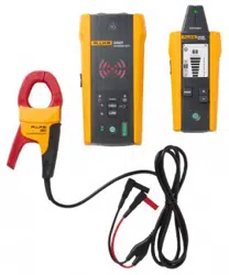
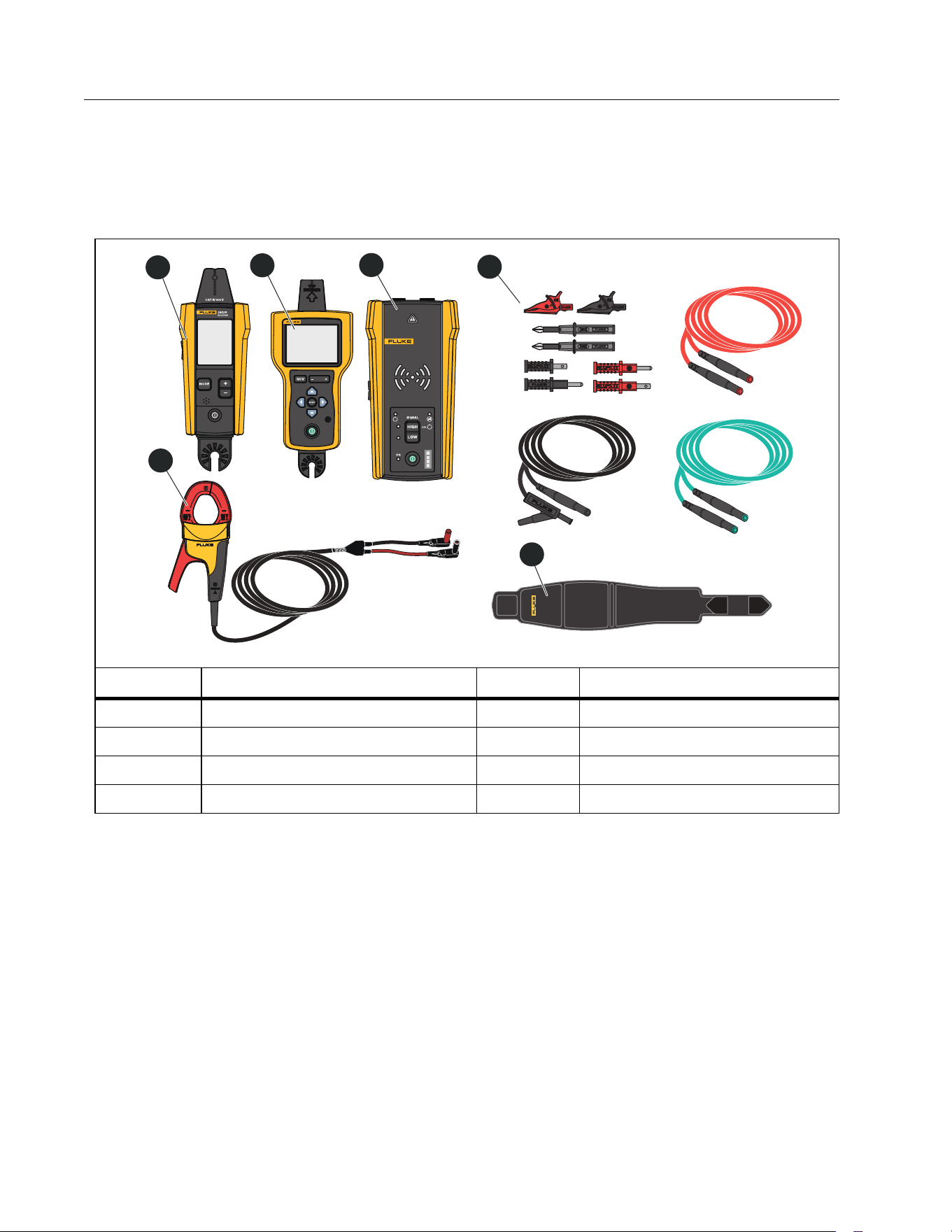
The Product
Ta b l e 1 shows the items that may ship with the Product as part of a kit. The items are available
for purchase individually.
Tab le 1. T he Produc t
Item Description Item Description
2052R receiver
i400 AC clamp (the Clamp)
2062R receiver
Magnetic strap
2000T transmitter Batteries, not shown
2000ACC accessories kit Case, not shown
i400
AC CURRENT CLAMP
2000T
TRANSMITTER
RECEIVER
2062R
3
1
4
2
6
5
1.888.610.7664 sales@GlobalTestSupply.com
Fluke-Direct.com
Wire Tracer Receiver and Transmitter
Receivers
3
Receivers
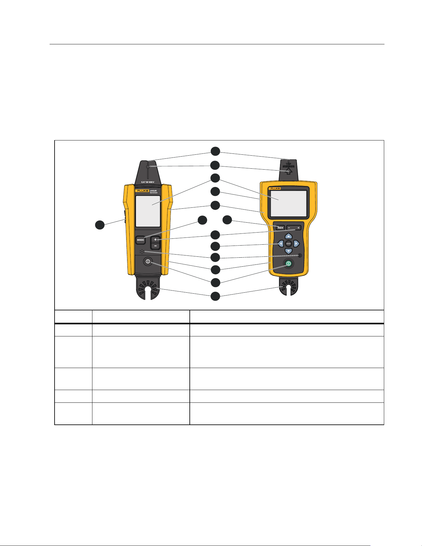
The 2052R and 2062R receivers have different features and displays, but the Receivers detect
energized or de-energized signals on wires in similar ways.
Features
Ta b l e 2 shows the features of the Receivers.
Table 2. Receivers Features
Item Description Function
Volume button (2052R) Adjusts the level of the volume the Product emits.
Tip sensor
Align the groove on top of the tip sensor with a wire or
fuse to detect an electromagnetic signal. See
Figure 9.
Tip sensor LED
Lights up when the Receiver detects an
electromagnetic signal.
Display Shows the settings, test functions, and results.
Smart Sensor detector
(2062R)
Located on the back of the Product. In Smart Sensor
mode, detects an electromagnetic signal.
RECEIVER
2062R
3
4
6
7
9
11
14
12
10
8
1
5
13
2
1.888.610.7664 sales@GlobalTestSupply.com
Fluke-Direct.com

2052R/2062R/2000T
Users Manual
4
Item Description Function
Tactile barrier
Warning
Hold the Product behind the tactile barrier.
Mode button (2052R)
Selects the mode. Push to cycle through the modes:
quick scan, tip sensor, breaker, non-contact voltage
(NCV) See Ta b l e 3 .
NCV button (2062R)
Selects non-contact voltage (NCV) mode.
Sensitivity button
2052R: B, C
2062R: G, H
Push to increase or to decrease the level of
sensitivity the Receiver uses to detect an
electromagnetic signal.
Navigation buttons
(2062R)
, , , ,
Use to navigate and set the menu options. See 2062R
Menu Navigation.
Speaker The Product emits a sound through the speaker.
Rubber over molded
holster
Protects the Product.
Power button
Turns on and off the Product.
Push <1 sec to turn on the Product.
Push and hold ≥2 sec to turn off the Product.
Hot stick attachment
point
Point to attach a hot stick (sold separately).
Table 2. Receivers Features
1.888.610.7664 sales@GlobalTestSupply.com
Fluke-Direct.com
Wire Tracer Receiver and Transmitter
Receivers
5
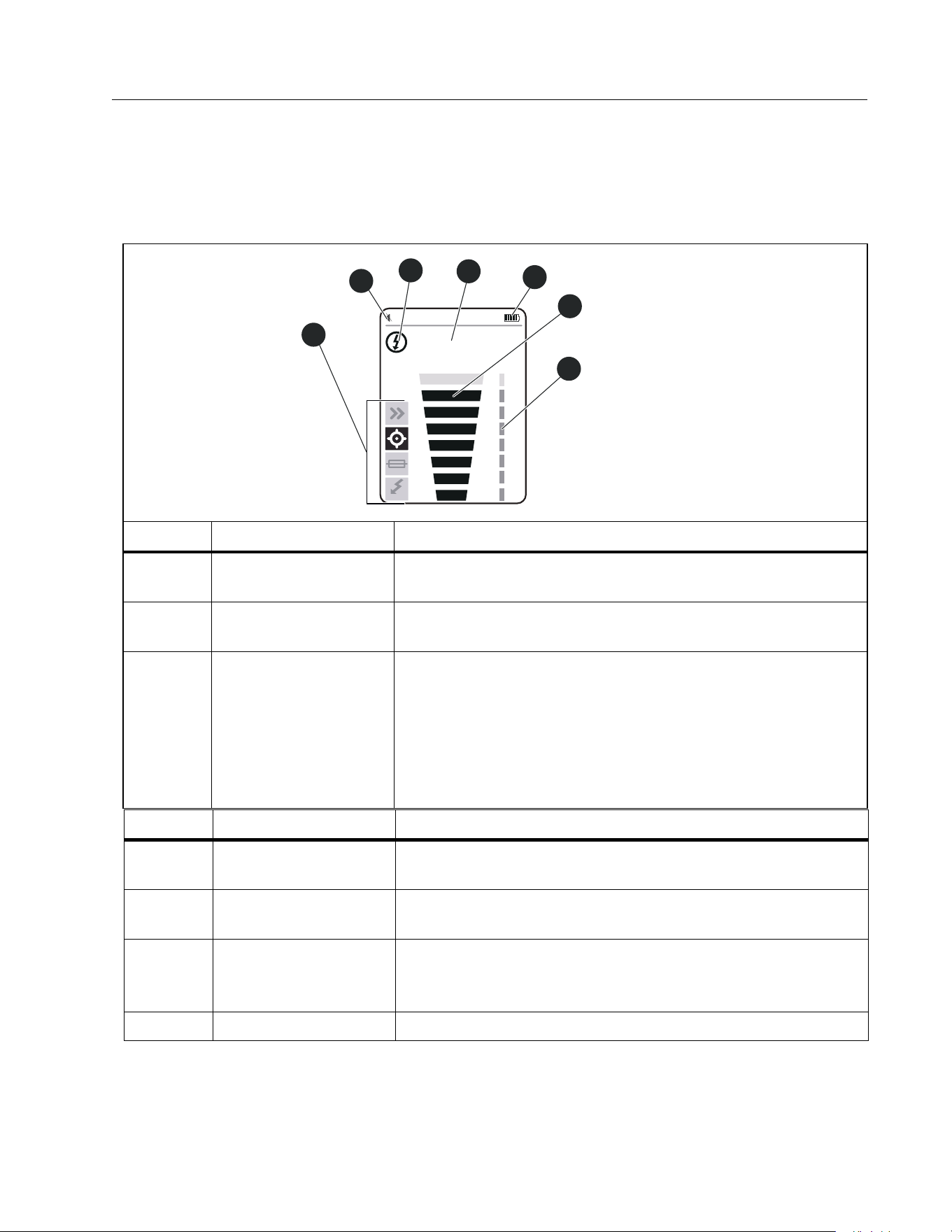
2052R Receiver Display
The display shows different features based on the selected mode. Ta b l e 3 shows the features
on the display of the 2052R receiver. To use the Receiver, see Use the Receiver.
Table 3. 2052R Display Features
Item Description Function
Tra ce mo de
indicators
Shows the selected mode. See Use the Receiver.
Volume level
indicator
Volume level
Energy status
indicator
: In non-NCV modes, the Receiver detects a signal on a
de-energized wire.
: In non-NCV modes, the Receiver detects a signal on an
energized wire. In NCV mode, the Receiver detects an AC
signal within the specifications of the Product.
See Tra n sm it te r.
NCV
88
6
7
4
2
5
1
3
Item Description Function
Numeric signal
strength level
In Precision, Breaker, or NCV mode, shows the strength of
the signal from 00 to 99.
Battery level
indicator
Battery power level
Signal strength
indicator
Based on the trace mode: Shows a toggle of signal
detected or not detected, or shows the strength of the
signal detected. See Use the Receiver.
Sensitivity level Shows the sensitivity level (1 to 8) of the Receiver.
1.888.610.7664 sales@GlobalTestSupply.com
Fluke-Direct.com
2052R/2062R/2000T
Users Manual
6
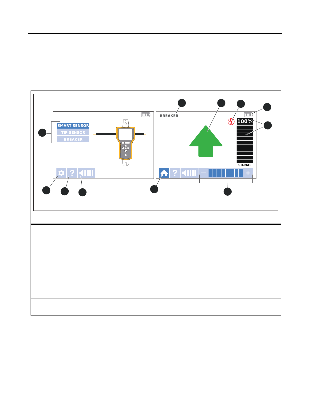
2062R Receiver Display
The display shows different features based on the selected mode. Ta b l e 4 shows the features
on examples of a home screen and a trace screen of the 2062R receiver. To use the Receiver,
see Use the Receiver.
Table 4. 2062R Display Features
Item Description Function
Tra ce mod e
selectors
Use with navigation buttons to set and show non-NCV trace
modes. See Change the Trace Mode.
Settings button
Opens the settings screen to select the language, brightness
of the screen, volume, and type of breaker (GFI or RCD). See
Change Settings.
Help button
Opens the help screen to show an explanation of the symbols
used on the interface. See View Help Screen.
Volume button
Opens the volume menu to change the volume the Receiver
emits. See Change the Volume.
Home button
While in a trace mode or on the help screen, returns to a
home screen.
3
4
5
1
2
6
7
8
9
10
11
A Home Screen A Trace Screen
1.888.610.7664 sales@GlobalTestSupply.com
Fluke-Direct.com

2052R/2062R/2000T
Users Manual
8
2062R Menu Navigation
Use the navigation buttons to change the trace mode, settings, or volume level, to view the
help screen, or to return to the home screen.
Change the Trace Mode
To c h a n g e t o N C V m o d e , p u s h .
While not in an active trace test, to change to a trace mode other than the NCV mode:
1. Push / to highlight a selection.
2. Push to set the selection.
When in an active trace test, push to return to the home screen to select a new mode.
Item Description Function
Sensitivity level
While in a trace mode, shows the sensitivity level (1 to 8) of
the Receiver.
Signal strength
indicator
In a trace mode, shows the strength of the signal in a bar
graph and as a percentage.
Battery level
indicator
Battery power level.
Energy satus
indicator
In a non-NCV trace mode, indicates the Receiver:
: Detects a de-energized signal on a wire.
: Detects an energized signal on a wire.
: Does not detect a signal from the Transmitter.
: In NCV mode, the Receiver detects an AC signal within the
specifications of the Product.
See Tra n sm it ter .
Tra ce m od e
information
In a trace mode, shows information about the trace test. See
Use the Receiver.
Trace mode Shows the selected trace mode.
Table 4. 2062R Display Features (cont.)
1.888.610.7664 sales@GlobalTestSupply.com
Fluke-Direct.com

Wire Tracer Receiver and Transmitter
Receivers
9
Change Settings
Use the settings menu to set the language, screen brightness, and the breaker type (GFCI or
RCD).
To change the settings:
1. Push to highlight h.
2. Push to open the settings menu.
3. Push /// to highlight a selection.
4. Push to set the selection.
5. To return to the home screen, Push /// to highlight f.
6. Push .
View Help Screen
To open the help screen:
1. Push to highlight h.
2. Push to highlight i.
3. Push to open the help menu.
4. Push to return to the home screen.
Change the Volume
To c h a n g e t h e v o l u m e :
1. Push to highlight h.
2. Push to highlight
e.
3. Push to open the volume menu.
4. Push / to adjust the volume.
5. Push to set the volume and return to the home screen.
1.888.610.7664 sales@GlobalTestSupply.com
Fluke-Direct.com
2052R/2062R/2000T
Users Manual
10
Transmitter
Use the Transmitter to generate a signal on an energized or de-energized wire.
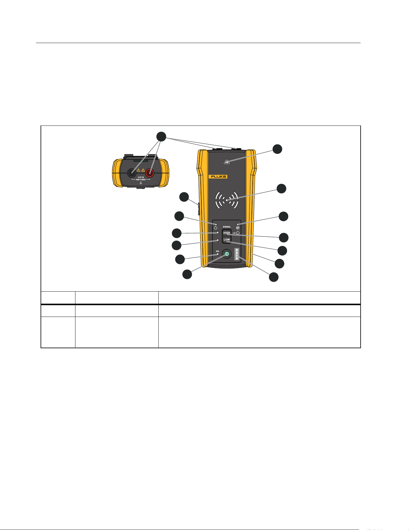
Features
Ta b l e 5 shows the features of the Transmitter.
Table 5. Transmitter Features
Item Description Function
Input jacks Use to connect the test leads to the Transmitter.
Voltage warning
indicator
With test leads connected to the circuit, indicates a de-
energized, energized, or over-voltage signal detected in a
circuit. See Set up the Transmitter.
2000T
TRANSMITTER
2
3
5
6
7
4
8
10
12
13
11
9
14
1
1.888.610.7664 sales@GlobalTestSupply.com
Fluke-Direct.com

Wire Tracer Receiver and Transmitter
Tr an s m i tt e r
11
Item Description Function
Tran s m i s s i o n mode
LEDs
Blinks to indicate the mode of operation.
Blinks quickly, progressively from the center to the
outermost LEDs: Indicates high signal mode.
Blinks slowly, progressively from the center to the
outermost LEDs: Indicates low signal mode.
All LEDs blink at the same time: Indicates loop mode.
Mute LED Turns on when the volume is muted.
High mode/Loop
mode button
With Transmitter on, push <1 sec to generate a high signal
on a wire. Push again to turn off high signal mode. See Set
up the Transmitter.
With Transmitter on and not in high or low signal mode,
push and hold ≥2 sec to turn on loop mode. See Set up the
Tra ns m it te r .
Low mode button A
With Transmitter on, push <1 sec to generate a low signal
on a wire. Push again to turn off low signal mode. See Set
up the Transmitter.
When in loop mode, push to turn off loop mode.
Rubber over molded
enclosure
Protects the Product.
Battery level Shows the battery power level.
Power button
Turns on and off the Transmitter.
Push <1 sec to turn on the Transmitter.
Push and hold ≥2 sec to turn off the Transmitter.
Power LED Emits light when the Transmitter is on.
Low mode LED Emits light when low mode is selected.
High mode LED Emits light when high mode is selected.
Loop mode LED Emits light when loop mode is selected.
Volume button Adjusts the level of the volume the Transmitter emits.
Table 5. Transmitter Features (cont.)
1.888.610.7664 sales@GlobalTestSupply.com
Fluke-Direct.com
2052R/2062R/2000T
Users Manual
12
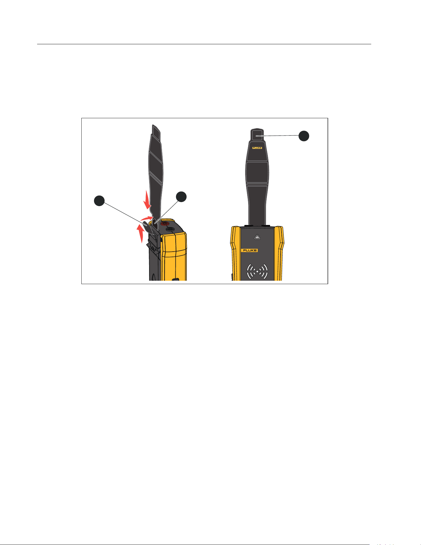
Magnetic Strap
To attach the magnetic strap to the Transmitter, insert the strap through the slot on the back
of the Transmitter and connect the hook and loop pieces
and to each other. See Figure 1.
Attach the magnet (
) to a metallic object such as a beam to support the Transmitter.
Figure 1. Magnetic Strap
2000T
TRANSMITTER
1
3
2
1.888.610.7664 sales@GlobalTestSupply.com
Fluke-Direct.com
Wire Tracer Receiver and Transmitter
The Clamp
13
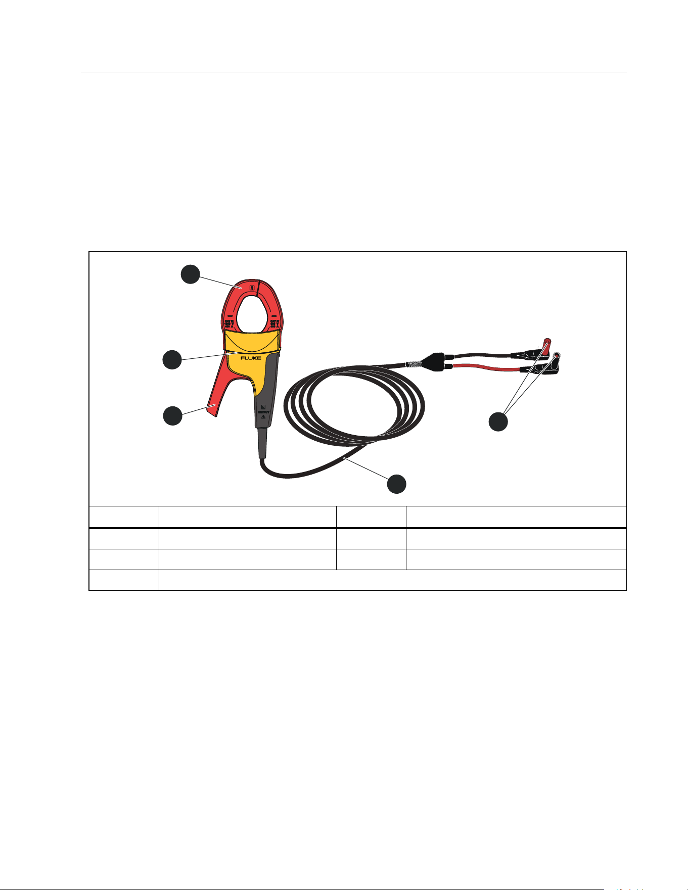
The Clamp
When a direct connection to a conductive wire is not possible, use the Clamp with the
Transmitter to generate a signal on a wire through the insulation around the wire. The Clamp
works on low impedance closed circuits or to trace conduits or shielded wires grounded on
both ends. To trace signal cables or de-energized wires or loads, first temporarily ground the
circuit on both ends.
Ta b l e 6 shows the features of the Clamp.
Table 6. Clamp Features
Item Description Item Description
Jaw
Te s t l e a d s
Tactile barrier
Connectors to Transmitter
Jaw release
i400
AC CURRENT CLAMP
3
1
4
2
5
1.888.610.7664 sales@GlobalTestSupply.com
Fluke-Direct.com

2052R/2062R/2000T
Users Manual
14
Connect the Transmitter
The Transmitter generates a signal on a wire which creates an electromagnetic field around
the wire. The Receiver detects the electromagnetic field to trace the wire.
With the Transmitter connected to two adjacent wires on the same circuit, the signal travels in
one direction through the first wire and returns in the opposite direction through the second
wire. This causes the creation of two electromagnetic fields around each wire with opposite
direction. The opposite fields partially or completely cancel each other out which makes it
difficult, if not impossible, to trace the signal.
Test Lead Connection
To connect the Transmitter to a wire with test leads:
1. For most applications, connect the red and green test leads directly to the Transmitter. The
polarity does not matter.
2. Connect the red test lead to the hot wire on the load-side of the circuit.
Note
For all applications, always connect the Transmitter on what would be the load-side of
an energized circuit whether or not the circuit is energized or de-energized.
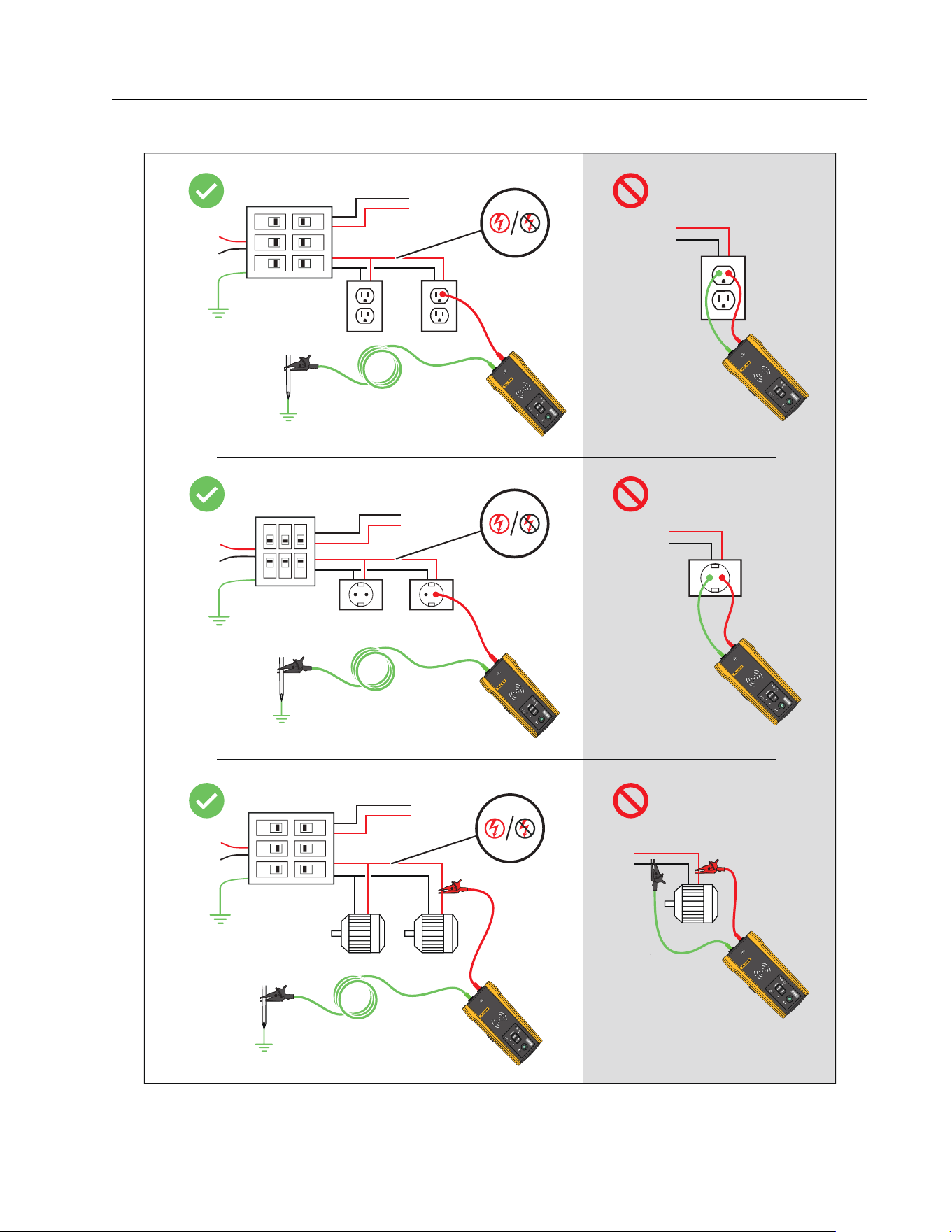
3. Determine which type of circuit the wire to trace is on:
Not connected to a GFI device or an RCD
Connected to a GFI outlet
Connected to a GFI breaker
Connected to an RCD
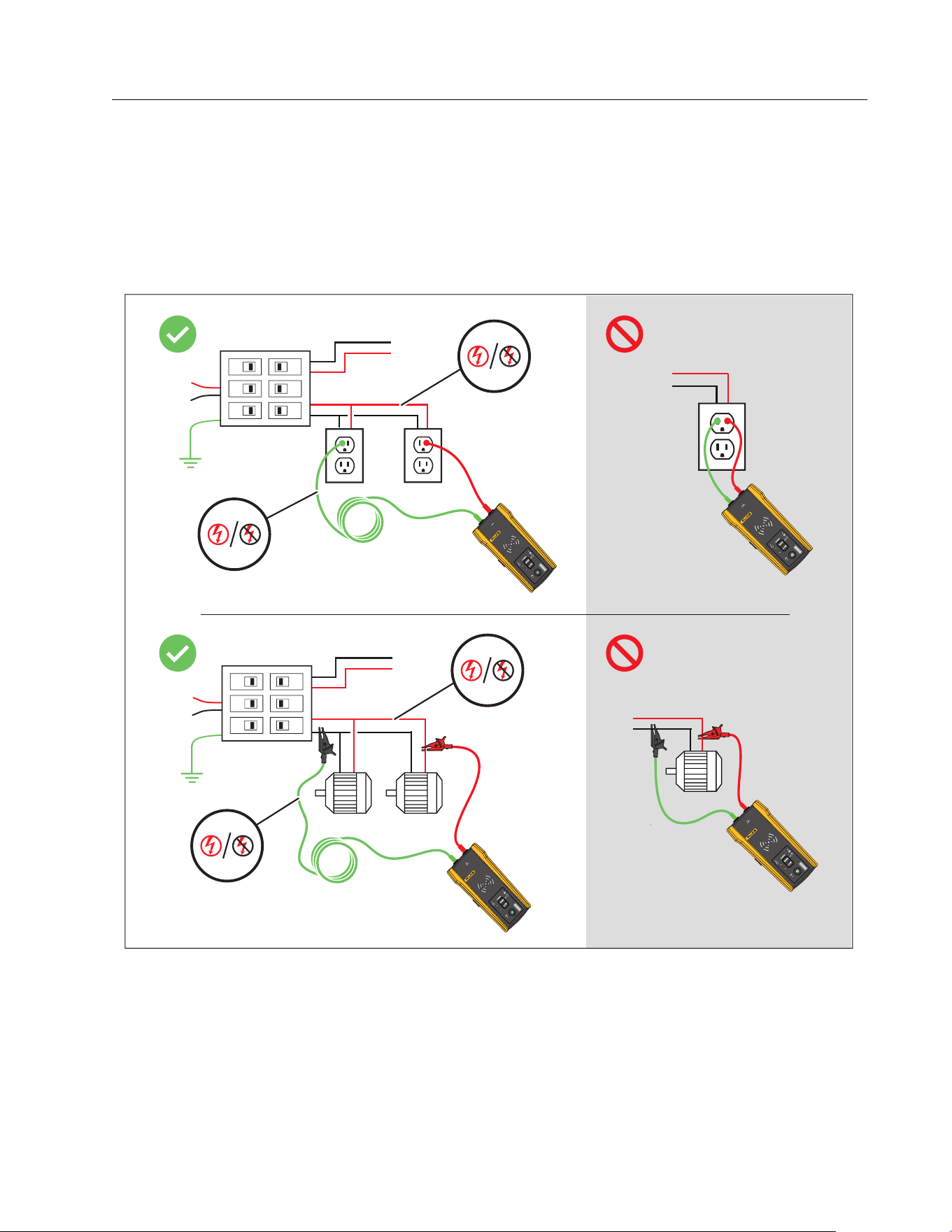
4. To trace a wire on a circuit not connected to a GFI device or an RCD, connect the green test
lead to a separate ground such as a metal water pipe, a metal grounded structure of the
building, a grounded screwdriver, or a grounded stake.
With the Transmitter connected to a ground wire on a different circuit than the hot wire, the
Receiver can detect the signal only if the wires on both circuits are connected correctly.
The best practice is to connect to a separate ground.
Outlet and breaker types vary. Figure 2 shows a few examples of outlet and breaker type
connections.
1.888.610.7664 sales@GlobalTestSupply.com
Fluke-Direct.com
Wire Tracer Receiver and Transmitter
Connect the Transmitter
15
Figure 2. Wire not Connected to a GFI Device or RCD
20
00T
TR
A
NSMIT
T
ER
2000T
TR
ANSMIT
TER
2000T
TR
ANSMIT
TER
20
00T
TR
A
NSMIT
T
ER
2000T
TR
ANSMIT
TER
20
00T
T
R
A
NSMIT
T
ER
1.888.610.7664 sales@GlobalTestSupply.com
Fluke-Direct.com
2052R/2062R/2000T
Users Manual
16
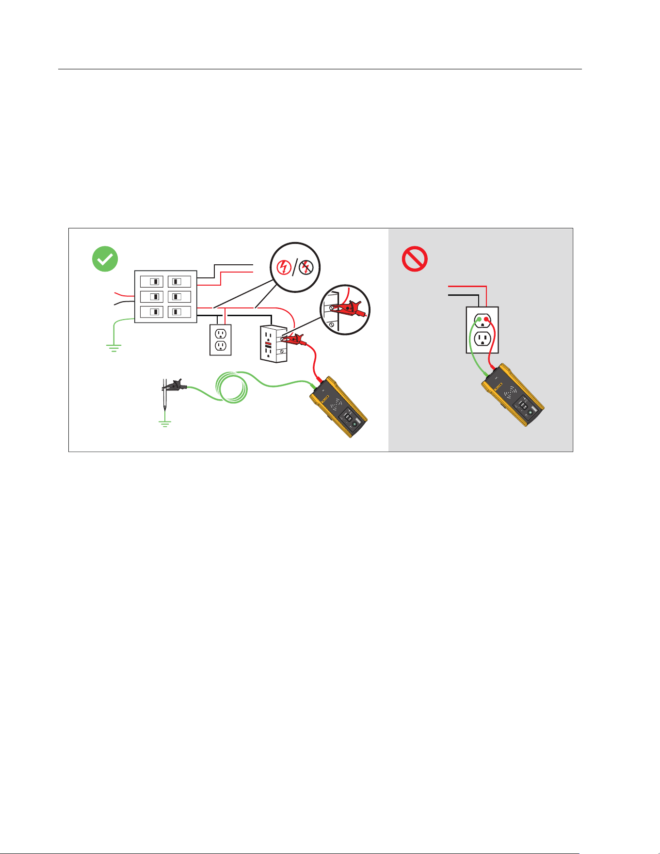
5. To trace a wire connected to a GFI outlet:
a. Remove the protective receptacle wall plate.
b. Connect the red alligator clip to the screw of the hot wire.
c. Connect the alligator clip of the green test lead to a separate ground such as a metal
water pipe, a metal grounded structure of the building, a grounded screwdriver, or a
grounded stake. See Figure 3.
Figure 3. Wire Connected to a GFI Outlet
2000T
TR
ANSMIT
TER
20
00T
TR
A
NSMIT
T
ER
1.888.610.7664 sales@GlobalTestSupply.com
Fluke-Direct.com
Wire Tracer Receiver and Transmitter
Connect the Transmitter
17
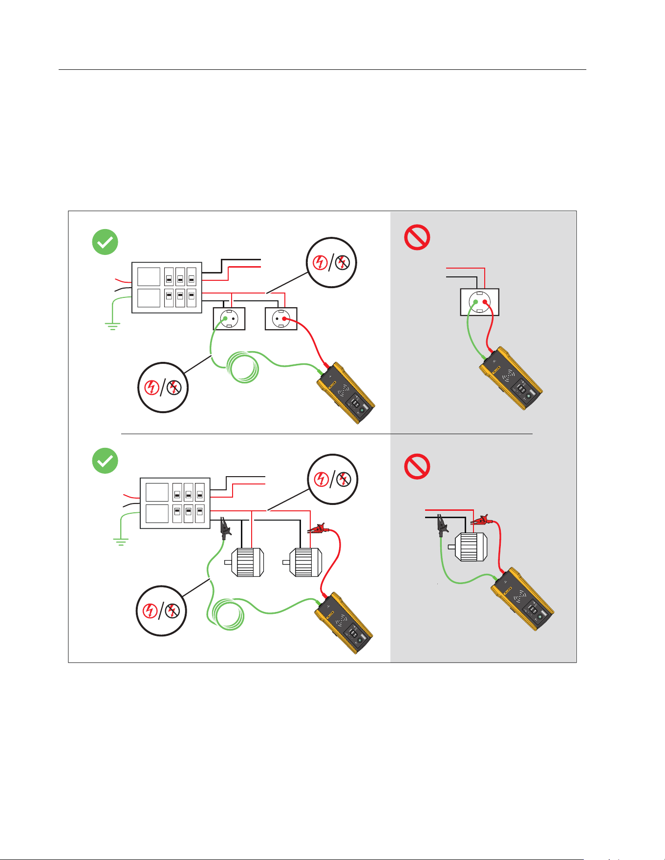
6. To trace a wire connected to a GFI breaker:
a. Locate the closest connection to the breaker or fuse panel that is on a different branch
of the same circuit that is connected to the same GFI breaker.
b. Connect the green test lead to the neutral wire of the identified closest connection. See
Figure 4.
Figure 4. Wire Connected to a GFI Breaker
2000T
TR
ANSMIT
TER
20
00T
TR
A
NSMIT
T
ER
2000T
TR
ANSMIT
TER
20
00T
TR
A
NSMIT
T
ER
1.888.610.7664 sales@GlobalTestSupply.com
Fluke-Direct.com
2052R/2062R/2000T
Users Manual
18
7. To trace a wire on a circuit connected to an RCD:
a. Locate the closest connection to the breaker or fuse panel that is on a different branch
of the same circuit that is connected to the same RCD as the line or phase wire.
b. Connect the green test lead to the neutral wire of the identified closest connection.
See Figure 5.
Figure 5. Wire Connected to an RCD
2000T
TR
ANSMIT
TER
RCD
RCD
20
00T
TR
A
NSMIT
T
ER
2000T
TR
ANSMIT
TER
20
00T
TR
A
NSMIT
T
ER
RCD
RCD
1.888.610.7664 sales@GlobalTestSupply.com
Fluke-Direct.com
Wire Tracer Receiver and Transmitter
Set up the Transmitter
19
Clamp Connection
Note
Because the Clamp does not have a direct connection to a conductive wire, the signal
may not be strong enough for the Receiver to detect very far from the Clamp. When
possible use test leads to make a direct connection to a conductive wire.
Warning
To prevent possible electrical shock, fire, or personal injury, read all safety
information in the i400 AC Clamp Instructions before you use the Clamp.
To connect the Transmitter to a wire with the Clamp (see Figure 6):
1. Connect the tests leads of the Clamp to the Transmitter. The polarity does not matter.
2. Connect the Clamp around the wire.
Figure 6. The Clamp Connection
Set up the Transmitter
With the Transmitter connected to a circuit and turned on, the Transmitter generates a signal
on a wire and detects the voltage on the wire. Based on the voltage detected, the Transmitter
automatically selects energized or de-energized mode. Loop mode only generates a signal on
de-energized wires in a closed circuit.
2000T
T
RANSMITTER
1.888.610.7664 sales@GlobalTestSupply.com
Fluke-Direct.com

2052R/2062R/2000T
Users Manual
20
Energized mode: When the Transmitter detects a voltage (≥35 V ac/dc to 600 V ac/dc and
40 Hz to 400 Hz) on the wire, the Transmitter operates in energized mode. In energized mode,
the Transmitter draws a low current from the energized circuit and generates a 6 kHz signal in a
direct path to the power source. The signal does not travel onto any of the branches of the
circuit. The low transmission frequency reduces signal coupling between wires. The signal
does not harm sensitive equipment connected to the circuit. To use energized mode, connect
the Transmitter on the load side of the circuit.
De-energized mode: When the Transmitter detects a voltage (<35 V ac/dc) on the wire, the
Transmitter operates in de-energized mode. In de-energized mode, the Transmitter generates
a 33 kHz signal that travels through all the branches of the circuit. De-energized mode uses a
higher frequency to generate a reliable signal. The signal does not harm sensitive equipment
on the circuit.
To use the Transmitter:
1. Connect the Transmitter. See Connect the Transmitter.
2. Push to turn on the Transmitter.
3. Verify the status of the voltage warning indicator shows as expected.
With test leads connected:
Off: Indicates a de-energized signal (<35 V ac/dc) in a circuit.
Solid red: Indicates an energized signal (≥35 V ac/dc to 600 V ac/dc and 40 Hz to
400 Hz) in a circuit.
Blinking red: Indicates an energized over-voltage signal (≥600 V ac/dc) in a circuit.
Warning
When the indicator blinks, disconnect the transmitter from the circuit
immediately.
Note
With the Clamp connected, the voltage warning indicator shows as off because the
Transmitter cannot determine if the wires inside the cable are energized or de-
energized.
4. Select a signal mode. Ta b le 7 lists the signal modes and describes the applications for
each mode.
1.888.610.7664 sales@GlobalTestSupply.com
Fluke-Direct.com

Wire Tracer Receiver and Transmitter
Use the Receiver
21
Use the Receiver
The Receiver can directly detect a signal on a wire through walls, floors, ceilings, and non-
metallic conduit or pipe. To indirectly trace a wire in non-metallic conduit or pipe, use
conductive fish tape or wire. See Conductive Fish Tape or Wire Method. The Receiver cannot
directly detect a signal on a wire through metallic conduit or pipe. Use the junction box method
to indirectly trace wires in metallic conduit. See Junction Box Method.
To use the Receiver:
1. Connect and set up the Transmitter in high mode unless otherwise noted.
2. Turn on the Receiver.
Note
Keep the Receiver >1 m (3 ft) from the Transmitter and test leads to minimize signal
interference.
3. If needed, open the settings screen to select the language, brightness of the screen,
volume, and type of breaker (GFI or RCD). See Change Settings.
4. If needed, select a mode. Ta b l e 8 lists the trace modes and describes the applications for
each mode.
a. On the 2052R receiver, push .
b. On the 2062R receiver, see Change the Trace Mode.
Tab l e 7. S i g nal M ode s
Mode Description
High Push <1 sec to use high mode for most applications.
Low
Push A to use low mode to trace a precise wire.
In low mode, the Transmitter generates a low signal level to not
oversaturate the Receiver with a signal that covers too large of an area. A
low signal level also reduces coupling to nearby wires and metal objects
that may make it difficult to trace a specific wire.
Loop
Push and hold for ≥2 sec to turn on loop mode.
Use loop mode to trace de-energized wires in a closed circuit such as
shorted wires, shielded cables, or wires grounded on the far end. Loop
mode automatically disables when the Transmitter connects to an
energized wire. Use loop mode for applications with the Clamp.
1.888.610.7664 sales@GlobalTestSupply.com
Fluke-Direct.com

2052R/2062R/2000T
Users Manual
22
5. To trace another wire in the same mode, push
.
6. To change to a different mode:
a. On the 2052R receiver, push .
b. On the 2062R receiver, push to select a NCV test, or push to return to the home
screen to select another mode. See Change the Trace Mode.
Smart Sensor Mode (2062R)
With a wire detected, Smart Sensor mode automatically adjusts the sensitivity of the Receiver.
The Receiver stores in memory the strongest signal detected. As a result, the Receiver
prevents manual adjustment of the sensitivity level.
To use Smart Sensor mode:
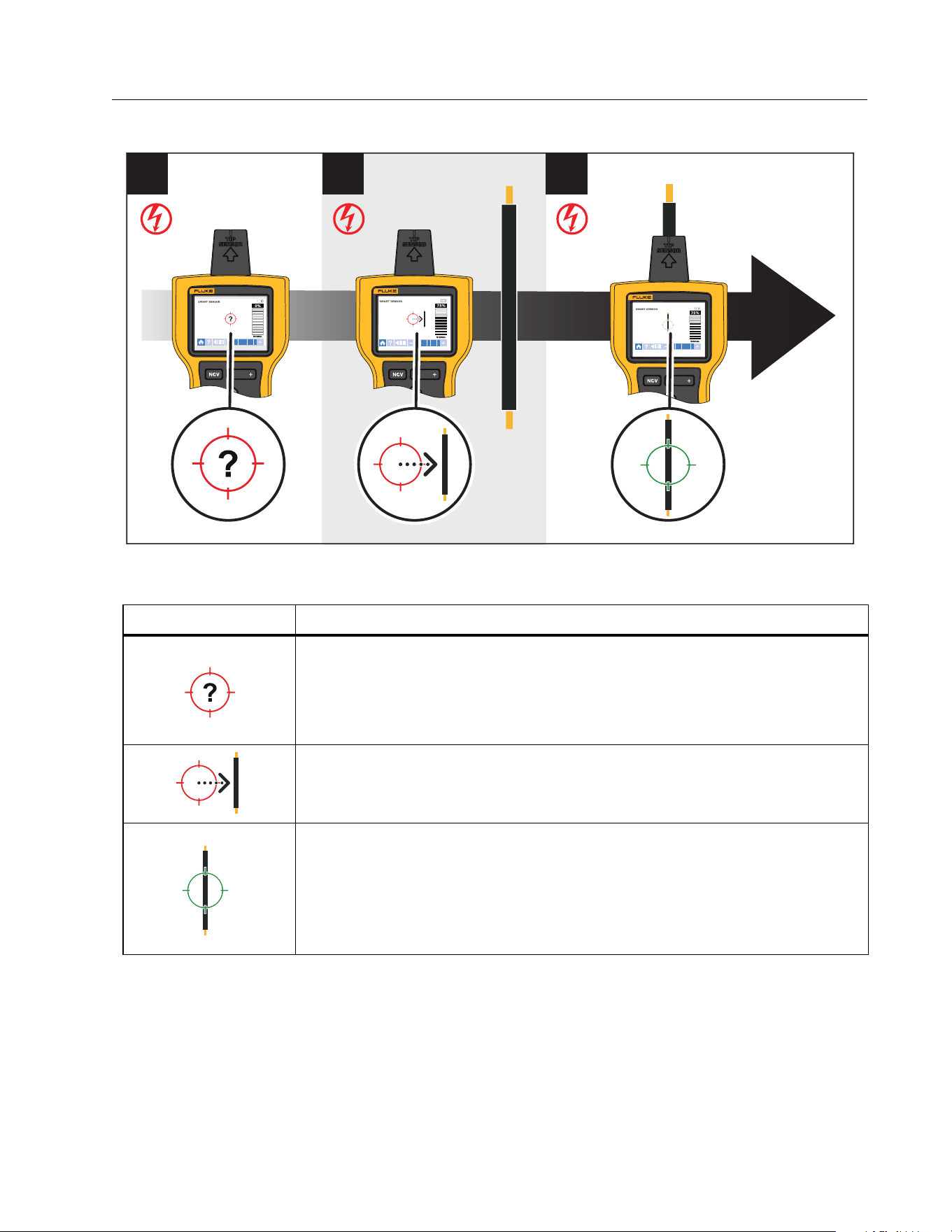
1. Hold the Receiver with the Smart Sensor toward the target area. See Figure 7.
2. Based on what shows on the display, move the Receiver to align with the wire. See Ta b l e 9 .
Tab l e 8. Tra ce Mod e s
Mode Description
Smart Sensor
SMART SENSOR
(2062R)
Use with the Transmitter and the arrows on the display of the Receiver
to see which way to move the Receiver to identify which wire connects
to the Transmitter. See Smart Sensor Mode (2062R).
Quick scan
K (2052R)
Use with the Transmitter to quickly identify the presence of a signal
and to follow the path to the wire. Does not identify a specific wire or
breaker. See Quick Scan Mode (2052R).
Tip sensor or
precision
J (2052R)
TIP SENSOR
(2062R)
Use with the Transmitter to identify which specific wire connects to the
Transmitter. Use to identify a wire in a bundle or to trace a wire in
corners, confined spaces such as junction boxes, or inside enclosures.
Also use to trace low-voltage wires such as data, audio, and thermostat
cables. See Tip Sensor Mode.
Breaker
(2052R)
BREAKER (2062R)
Use with the Transmitter to identify which fuse or breaker connects to
the Transmitter. See Breaker Mode.
Non-contact
voltage (NCV)
(2052R)
(2062R)
Use without the Transmitter to identify the generalized presence of an
energized wire (90 V ac to 600 V ac and 40 Hz to 400 Hz). No current
flow is necessary.
1.888.610.7664 sales@GlobalTestSupply.com
Fluke-Direct.com
Wire Tracer Receiver and Transmitter
Use the Receiver
23
Figure 7. SMART SENSOR Mode
Table 9. SMART SENSOR Mode Display
Display Description and Action
The Receiver cannot detect a signal or the signal is not strong enough
for the Receiver to show where the wire is located.
Move the Receiver closer to the target area.
If a signal is still not detected, push
to increase the sensitivity.
Move the Receiver in the direction indicated by the arrow: horizontally,
vertically, or diagonally.
The Receiver is directly over the wire.
If the wire does not stay aligned with the green target, push
to
decrease the sensitivity.
If the wire still does not align with the target: On the Transmitter, push
A to generate a low signal to trace more precisely.
1
2 3
RECEIVER
2062R
RECEIVER
2062R
RECEIVER
2062R
1.888.610.7664 sales@GlobalTestSupply.com
Fluke-Direct.com
2052R/2062R/2000T
Users Manual
24
Quick Scan Mode (2052R)
To u s e q u i c k sc a n m o d e :
1. Scan a target area with the tip sensor to find a signal.
The signal strength indicator on the display changes. See Figure 8.
Figure 8. Quick Scan Signal Strength
2. If needed, push
/ to increase or decrease the sensitivity to locate the signal.
3. With the signal detected, change to precision mode or breaker mode. See Tip Sensor
Mode.
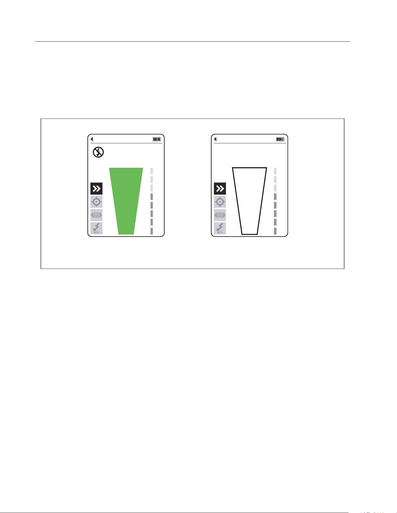
Tip Sensor Mode
To use tip sensor mode:
1. Scan a target area with the tip sensor to find the highest signal level.
2. With a wire detected, align the tip sensor perpendicular to the wire to find the highest signal
level. Align the groove on the top of the tip sensor parallel to the wire. See Figure 9.
3. To verify the direction of the wire, periodically rotate the Receiver 90 degrees from side to
side while the tip sensor remains perpendicular to the wire.
Signal Detected Signal not Detected
1.888.610.7664 sales@GlobalTestSupply.com
Fluke-Direct.com
Wire Tracer Receiver and Transmitter
Use the Receiver
25
Figure 9. Tip Sensor Alignment
4. Periodically adjust the sensitivity to keep the signal strength near 75 %.
The signal strength indicator on the display changes. For the 2052R display, see Figure 10.
For the 2062R display, see Figure 11.
5. If the signal is too strong to precisely locate the wire, change the Transmitter to low mode.
Figure 10. Tip Sensor Signal Strength (2052R)
90q
90q
RECEIVER
2062R
RECEI
V
E
R
2062R
Groove
Signal Detected Signal not Detected
1.888.610.7664 sales@GlobalTestSupply.com
Fluke-Direct.com

2052R/2062R/2000T
Users Manual
26
Figure 11. Tip Sensor Signal Strength (2062R)
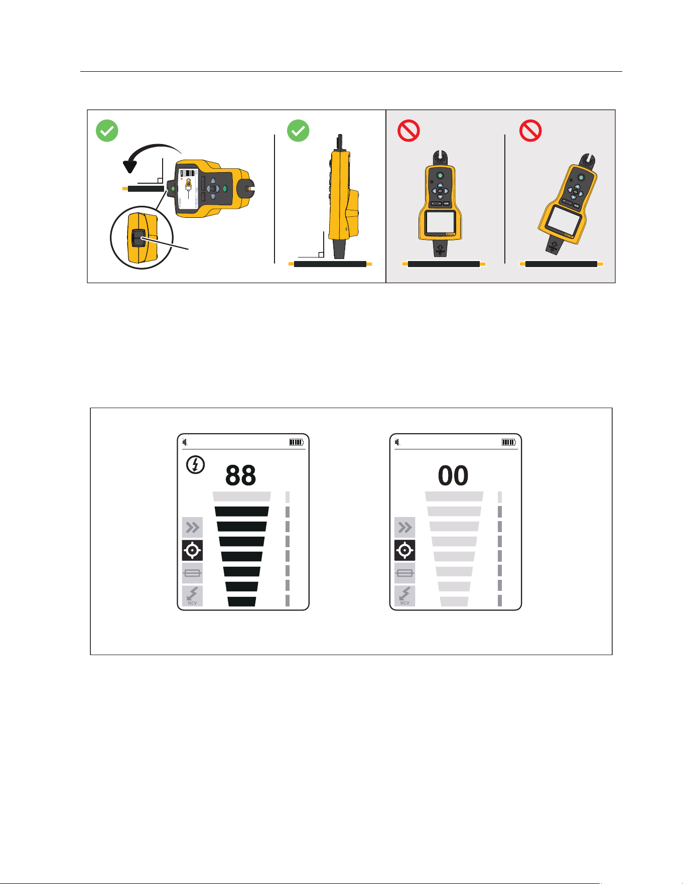
Breaker Mode
Breaker mode automatically adjusts the sensitivity of the Receiver. The Receiver stores in
memory the strongest signal detected. As a result, the Receiver identifies one correct breaker.
To use breaker mode:
1. To trace a breaker or fuse on a circuit with a light dimmer, turn off the light switch to
prevent multi-frequency signals on the wire.
2. Align the tip sensor perpendicular to the breaker. The groove on the top of the tip sensor
aligns parallel to the breakers. See Figure 12.
Note
Different breaker or fuse designs, height, or internal contact structure may affect the
precision of breaker or fuse identification. For best results, remove the breaker or fuse
panel cover, and do the scan on the wires instead of the breakers or fuses.
Signal Detected Signal not Detected
1.888.610.7664 sales@GlobalTestSupply.com
Fluke-Direct.com
Wire Tracer Receiver and Transmitter
Use the Receiver
27
Figure 12. Breaker Mode Alignment
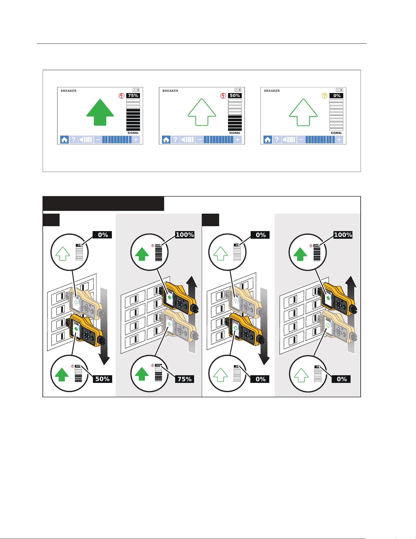
3. Scan each breaker or fuse multiple times until the arrow on the display shows solid green
for only one breaker or fuse. For best results, scan at the output of the breaker or fuse. The
order you scan the breakers or fuses does not matter.
The signal strength indicator on the display changes. For the 2052R display, see Figure 13.
For the 2062R display, see Figure 14. For a breaker mode application, see Figure 15.
Figure 13. Breaker Signal Strength (2052R)
75 50 00
Strongest Signal Detected Signal Detected Signal not Detected
1.888.610.7664 sales@GlobalTestSupply.com
Fluke-Direct.com
2052R/2062R/2000T
Users Manual
28
Figure 14. Breaker Signal Strength (2062R)
Figure 15. Breaker Mode Application
Strongest Signal Detected Signal Detected Signal not Detected
(2052R) / BREAKER (2062R)
M
2X
1X
1.888.610.7664 sales@GlobalTestSupply.com
Fluke-Direct.com
Wire Tracer Receiver and Transmitter
Use the Receiver
29
NCV Mode
Warning
The voltage indication in NCV mode does not indicate the absence of voltage.
Always verify that wires are de-energized with an additional tester.
To u s e N C V m o d e :
1. Scan a target area with the tip sensor to find the highest signal level.
2. With a wire detected, align the tip sensor perpendicular to the wire to find the highest signal
level. The groove on the top of the tip sensor aligns parallel to the wire. See Figure 9.
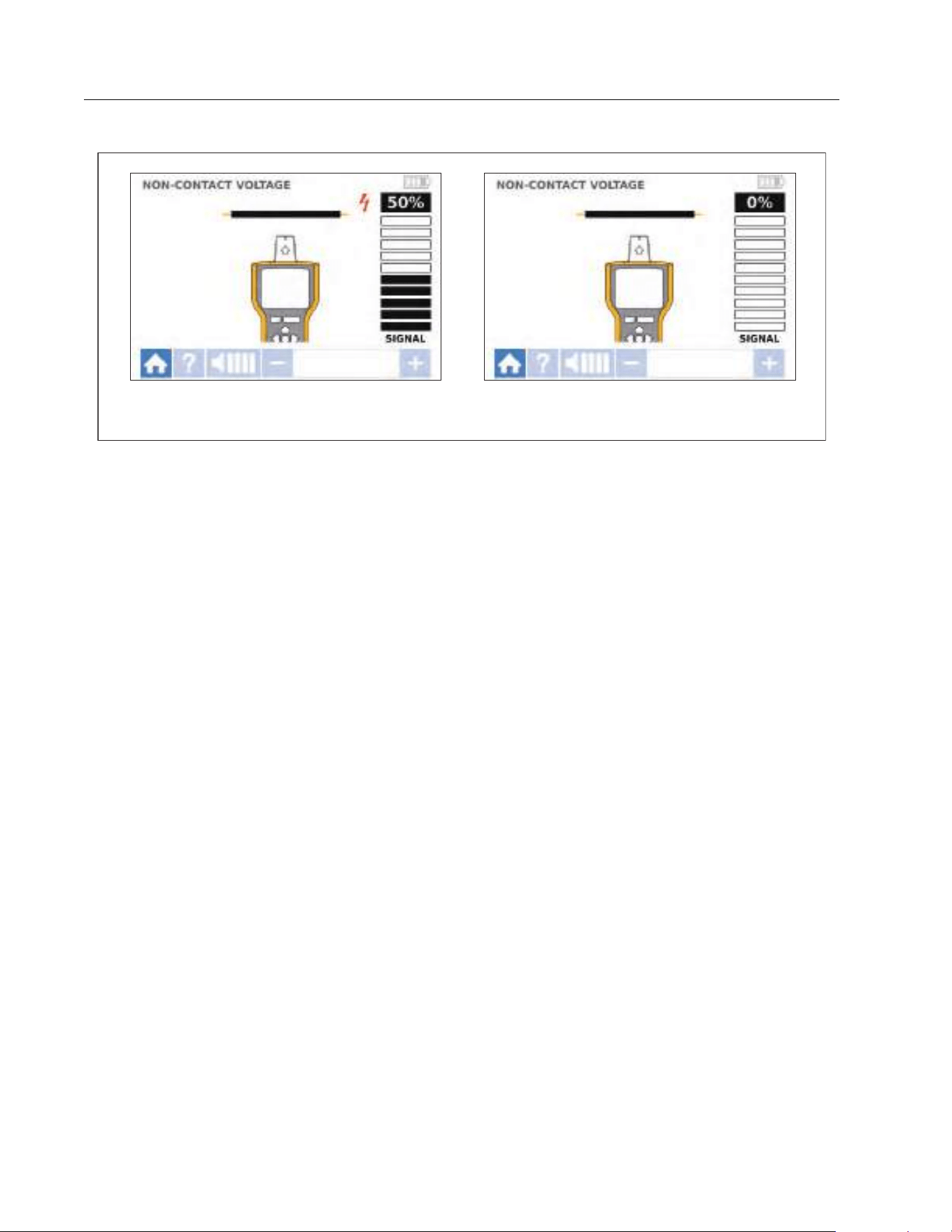
3. Periodically adjust the sensitivity to keep the signal strength near 75 %.
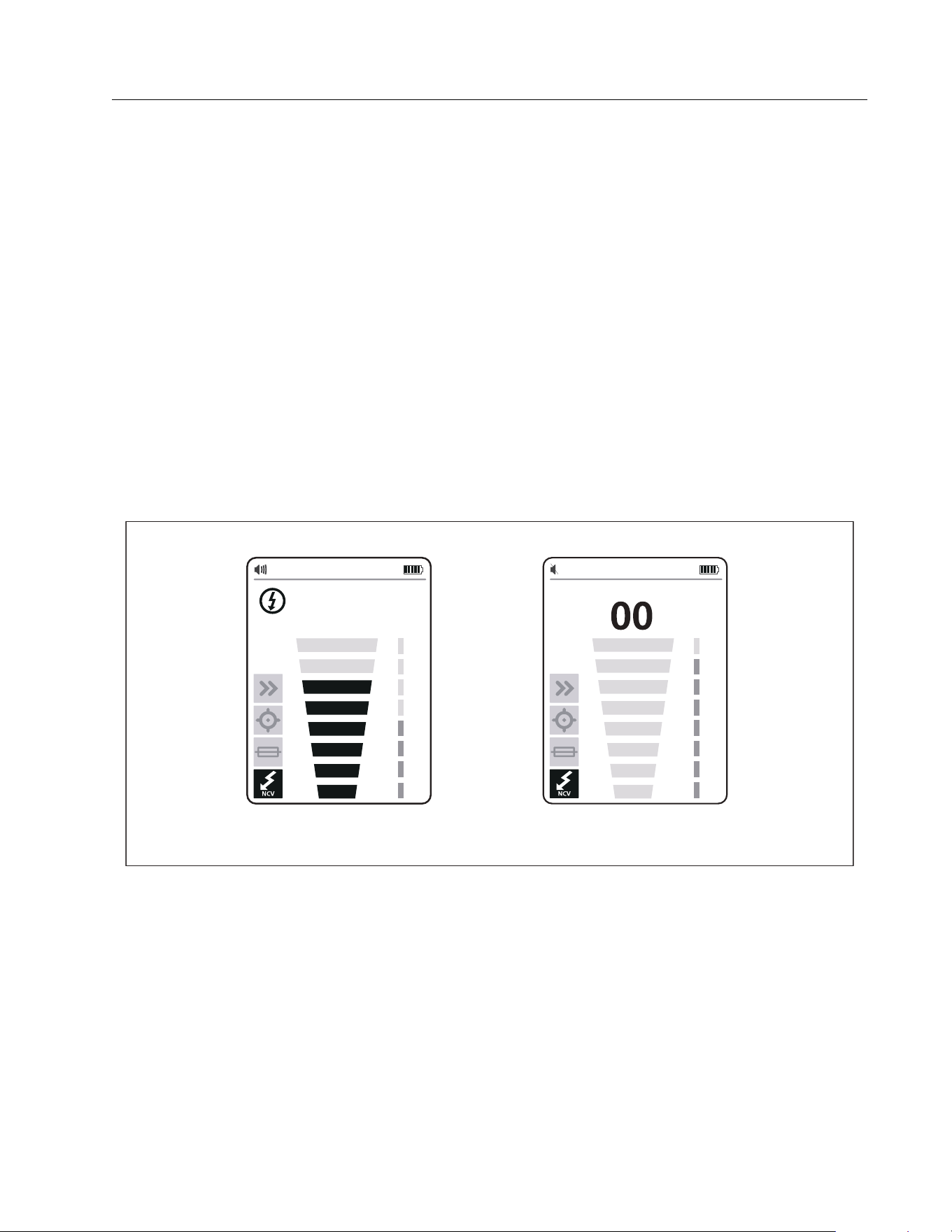
The signal strength indicator on the display changes. For the 2052R display, see Figure 16.
For the 2062R display, see Figure 17.
4. To identify the line or phase wire from the neutral wire, increase or decrease the sensitivity.
Figure 16. NCV Signal Strength (2052R)
75
Signal Detected Signal not Detected
1.888.610.7664 sales@GlobalTestSupply.com
Fluke-Direct.com
2052R/2062R/2000T
Users Manual
30
Figure 17. NCV Signal Strength (2062R)
Special Applications
For general instructions to connect the Transmitter, see Connect the Transmitter. Some
applications require the test leads to connect differently. For all applications, connect the
Transmitter on what would be the load-side of an energized circuit whether or not a circuit is
energized or de-energized.
Find a Broken or Open Wire
The signal generated by the Transmitter conducts along the wire while there is continuity in the
metal conductor.
Note
Natural materials in the earth, concrete, or asphalt and buried metal conduits can make
it difficult to trace a wire located underground.
Signal Detected Signal not Detected
1.888.610.7664 sales@GlobalTestSupply.com
Fluke-Direct.com
Wire Tracer Receiver and Transmitter
Special Applications
31
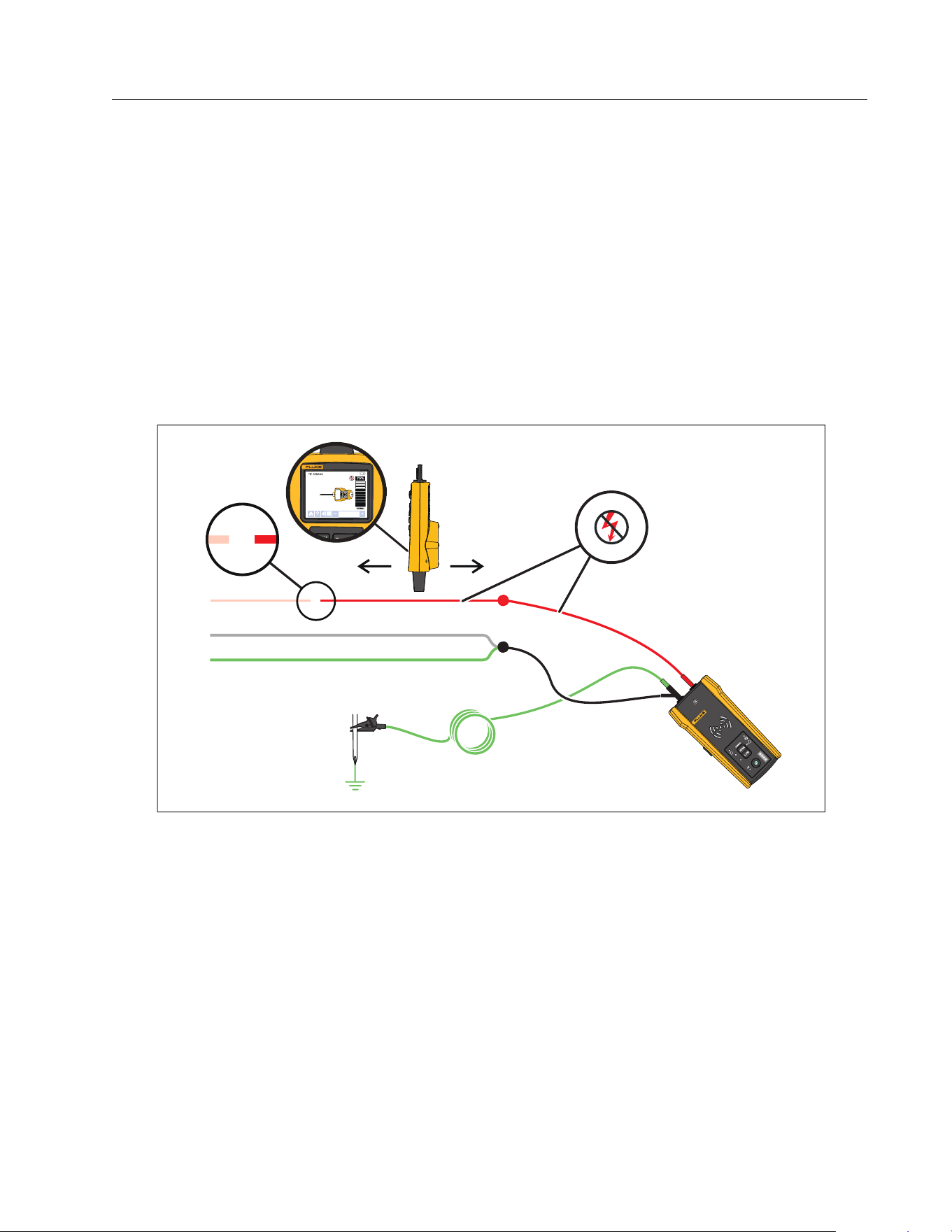
To find the location of a broken wire located behind walls, floors, or ceilings:
1. De-energize the wire.
2. Connect the Transmitter to the circuit. See Figure 18.
a. Connect the red test lead to the circuit.
b. Connect the black stackable test lead to the Transmitter.
c. Connect one end of the green test lead to the black test lead and the other end to a
separate ground.
d. Connect additional test leads as needed to ground all unused de-energized wires on
the Transmitter side of the circuit that run in parallel with the black test lead.
Figure 18. Trace a Broken Wire
3. On the Receiver, select Smart Sensor mode or tip sensor mode.
4. Trace the wire until the signal stops.
5. Mark the location where the signal stops.
1.888.610.7664 sales@GlobalTestSupply.com
Fluke-Direct.com

2052R/2062R/2000T
Users Manual
32
6. Verify the location of the broken wire.
a. Move the Transmitter to the other end of the wire.
b. Trace from the opposite end of the wire to the location the signal stopped in the
previous step.
Note
The Receiver may not detect a break in a wire in a high-resistance break which is a
partially-open circuit. A high-resistance break stops the flow of higher-level currents
but still conducts the signal through the break. Until the break in the wire is completely
open, the Receiver may not detect the location of the broken wire.
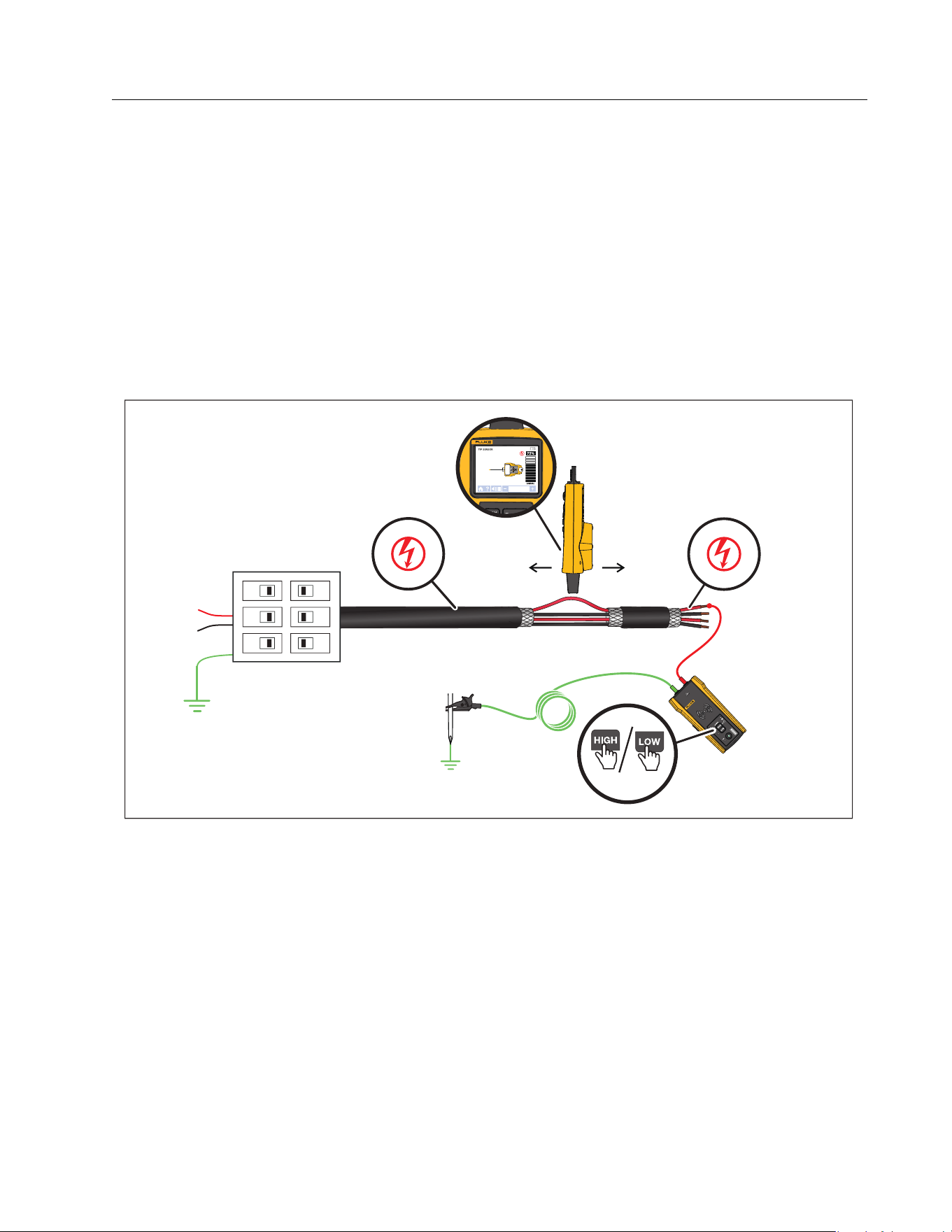
Find a Short in a Circuit
When wires in a circuit touch, they cause a short in the circuit which causes the breaker or fuse
to trip or turn off.
To correct a short in a circuit:
1. Disconnect the wires.
2. Isolate the ends of the wire on both sides of the cable so that they do not touch each other
or other wires or loads.
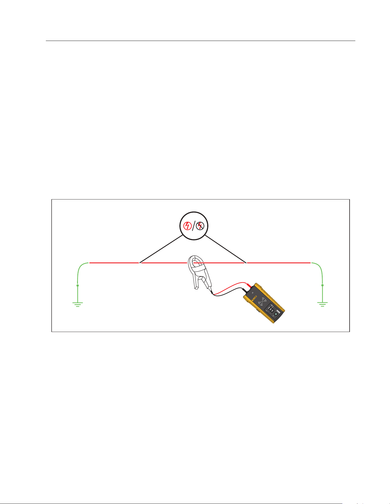
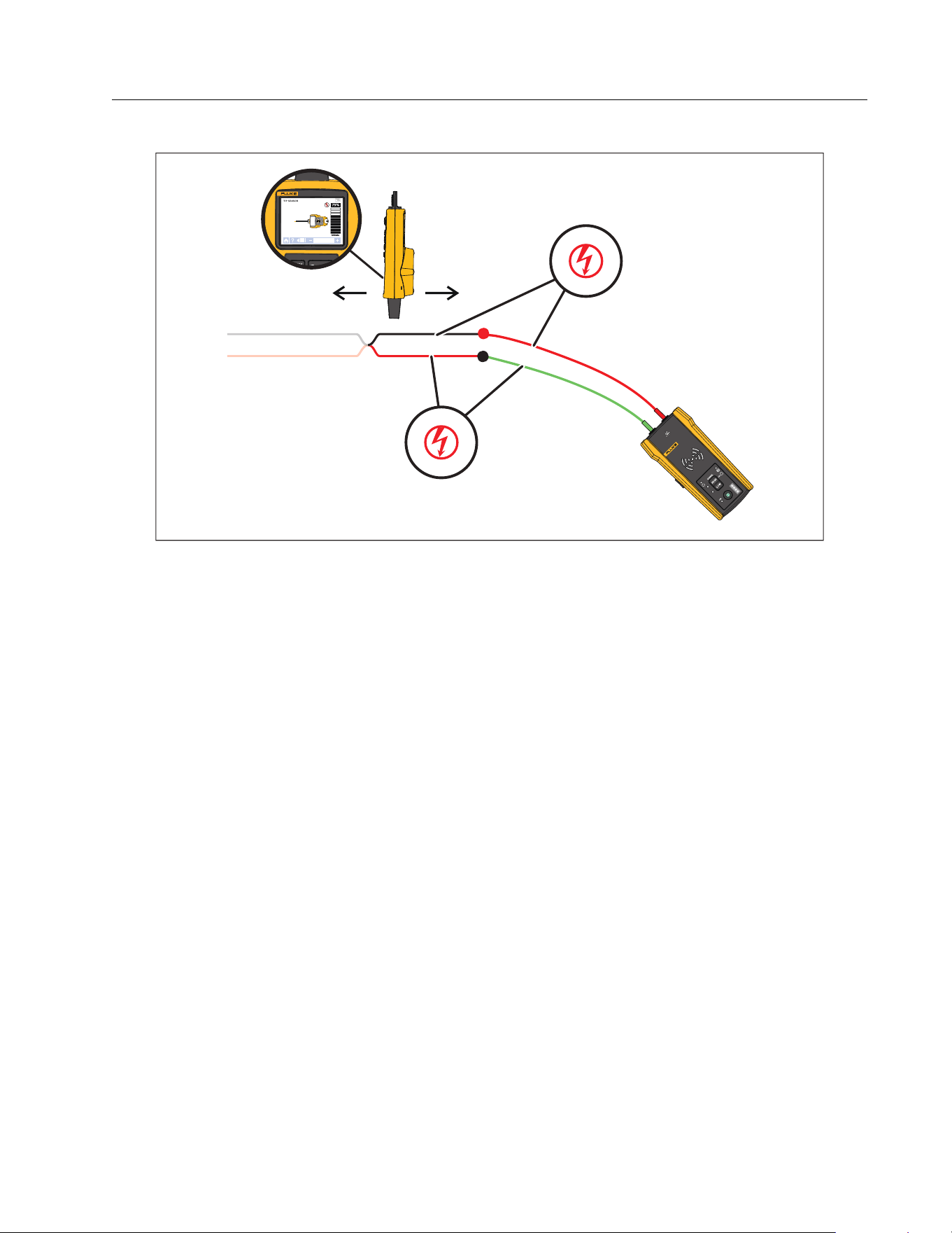
To find the location of a short in a circuit:
1. Disconnect the wires.
2. Connect the Transmitter to the ground wire on the same circuit as the hot wire. See
Figure 19.
Note
The signal may be weak and difficult to detect due to the cancellation effect. See
Connect the Transmitter.
1.888.610.7664 sales@GlobalTestSupply.com
Fluke-Direct.com
Wire Tracer Receiver and Transmitter
Special Applications
33
Figure 19. Trace a Short Circuit
3. On the Transmitter, select loop mode.
4. On the Receiver, select tip sensor mode.
5. Trace the wire until the signal stops.
6. Mark the location where the signal stops.
7. Verify the location of the short in the wire.
a. Move the Transmitter to the other end of the wire.
b. Trace from the opposite end of the wire to the location the signal stopped in the
previous step.
1.888.610.7664 sales@GlobalTestSupply.com
Fluke-Direct.com

2052R/2062R/2000T
Users Manual
34
Trace Wires in Conduit or Pipe
You can use one of the alternative methods to trace a wire inside a conduit or pipe.
Junction Box Method
To use the junction box method to trace a wire inside conduit or pipe:
1. Connect the Transmitter.
2. On the Receiver, select tip sensor mode.
3. Open the closest junction box that is to the Transmitter.
4. Use the tip sensor to identify which wire in the junction box carries the signal.
5. Move from junction box to junction box to follow the path of the wire.
Conductive Fish Tape or Wire Method
To use conductive fish tape to trace a wire inside non-metallic conduit or pipe:
1. Insert conductive fish tape or wire inside the conduit.
2. Connect the Transmitter.
a. Connect the red test lead to the conductive fish tape or wire.
b. Connect the green test lead to a separate ground.
3. On the Receiver, select tip sensor mode to trace the conduit or pipe.
The Receiver detects the signal the fish tape or wire conducts through the conduit or pipe.
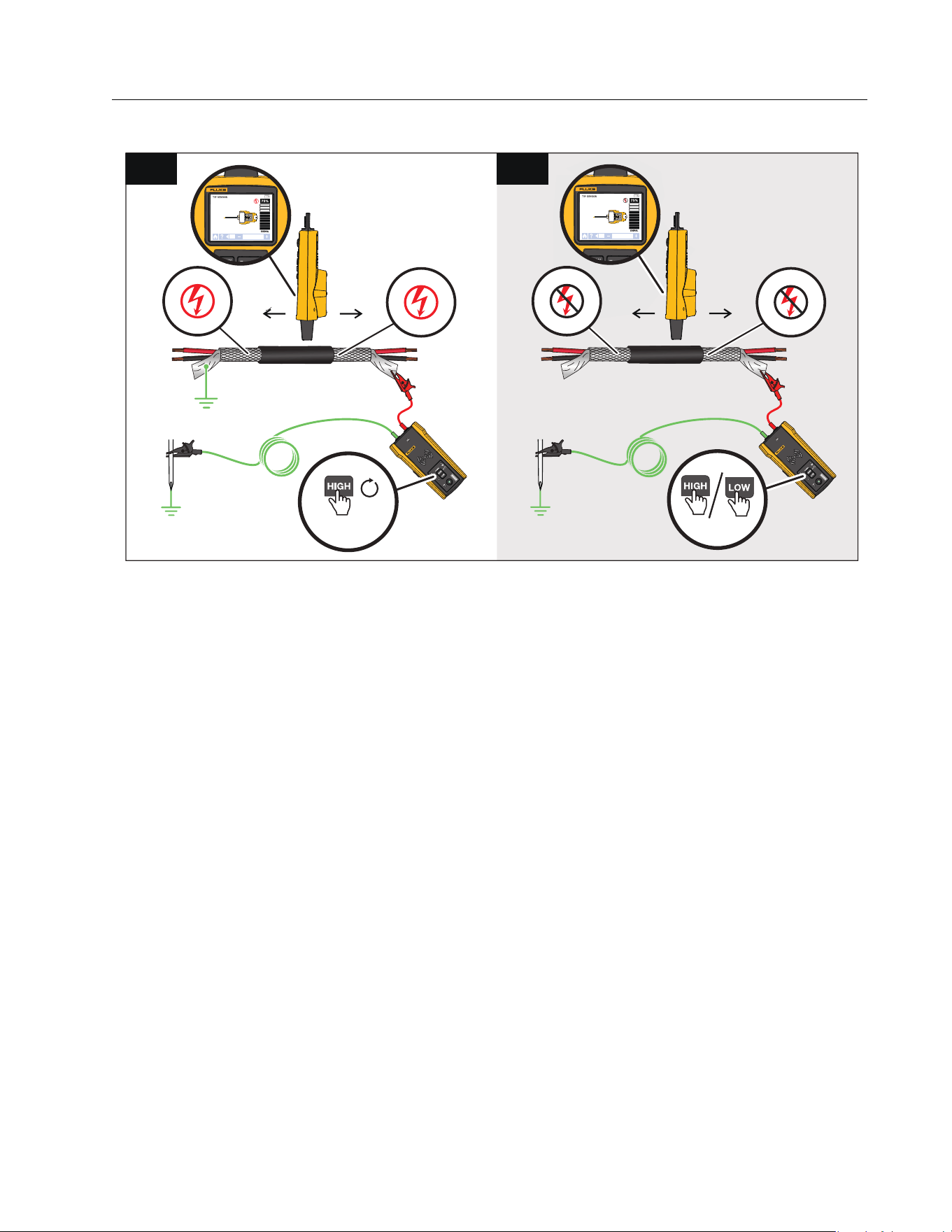
Trace a Shielded Wire
To trace a shielded wire:
1. Disconnect the ground on the near-end of the shielded wire.
2. Connect the Transmitter. With a wire grounded at the far-end, see Figure 20 A. With the
wire not grounded at the far-end, see Figure 20 B.
a. Connect one end of a test lead to the shield on the wire and the other end to the
Transmitter (polarity does not matter).
b. Connect one end of the second test lead to the Transmitter and the other end to a
separate ground.
1.888.610.7664 sales@GlobalTestSupply.com
Fluke-Direct.com
Wire Tracer Receiver and Transmitter
Special Applications
35
Figure 20. Trace a Shielded Wire
3. On the Transmitter:
With a wire grounded at the far-end, select loop mode. See Figure 20 A. The loop mode LED
lights.
Or,
With a wire not grounded at the far-end, select high or low mode. See Figure 20 B. The high
or low mode LED lights.
4. On the Receiver, select tip sensor mode to trace the wire.
B
<1 s
A
≥2 s
1.888.610.7664 sales@GlobalTestSupply.com
Fluke-Direct.com
2052R/2062R/2000T
Users Manual
36
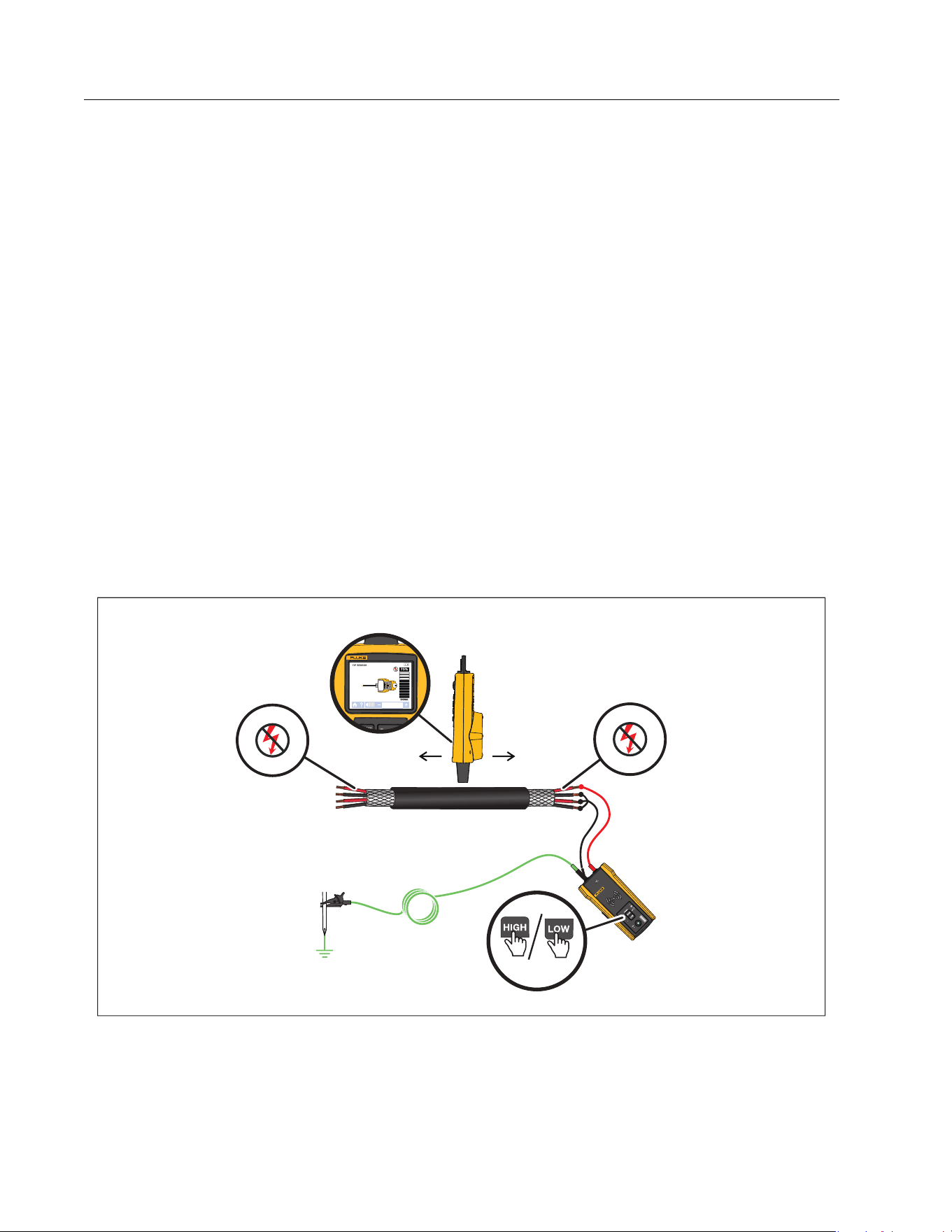
Find a Wire in a Bundle
To identify a wire in a bundle, first determine if the wire is on an energized or de-energized
circuit.
De-energized Circuit
To identify a wire in a bundle in a de-energized circuit:
1. Connect the Transmitter. See Figure 21.
a. Connect the red test lead to the circuit.
b. Connect the black stackable test lead to the Transmitter.
c. Connect one end of the green test lead to the black test lead and the other end to a
separate ground.
d. Connect additional test leads as needed to ground all unused de-energized wires on
the Transmitter side of the circuit that run in parallel with the black test lead.
2. On the Receiver, select tip sensor mode.
3. Pull one wire out as far as possible from other wires in the bundle and touch it with the tip
sensor. The strongest signal indicates the proper wire in the bundle.
Figure 21. Trace a Bundled Wire in a De-energized Circuit
<1 s
1.888.610.7664 sales@GlobalTestSupply.com
Fluke-Direct.com
Wire Tracer Receiver and Transmitter
Special Applications
37
Energized Circuit
To identify a wire in a bundle in an energized circuit:
1. Connect the Transmitter. See Figure 21.
a. Connect the red test lead to the circuit.
b. Connect the green test lead to a separate ground.
2. On the Receiver, select tip sensor mode.
3. Pull one wire out as far as possible from other wires in the bundle and touch it with the tip
sensor. The strongest signal indicates the proper wire in the bundle.
Figure 22. Trace a Bundled Wire in an Energized Circuit
<1 s
1.888.610.7664 sales@GlobalTestSupply.com
Fluke-Direct.com

2052R/2062R/2000T
Users Manual
38
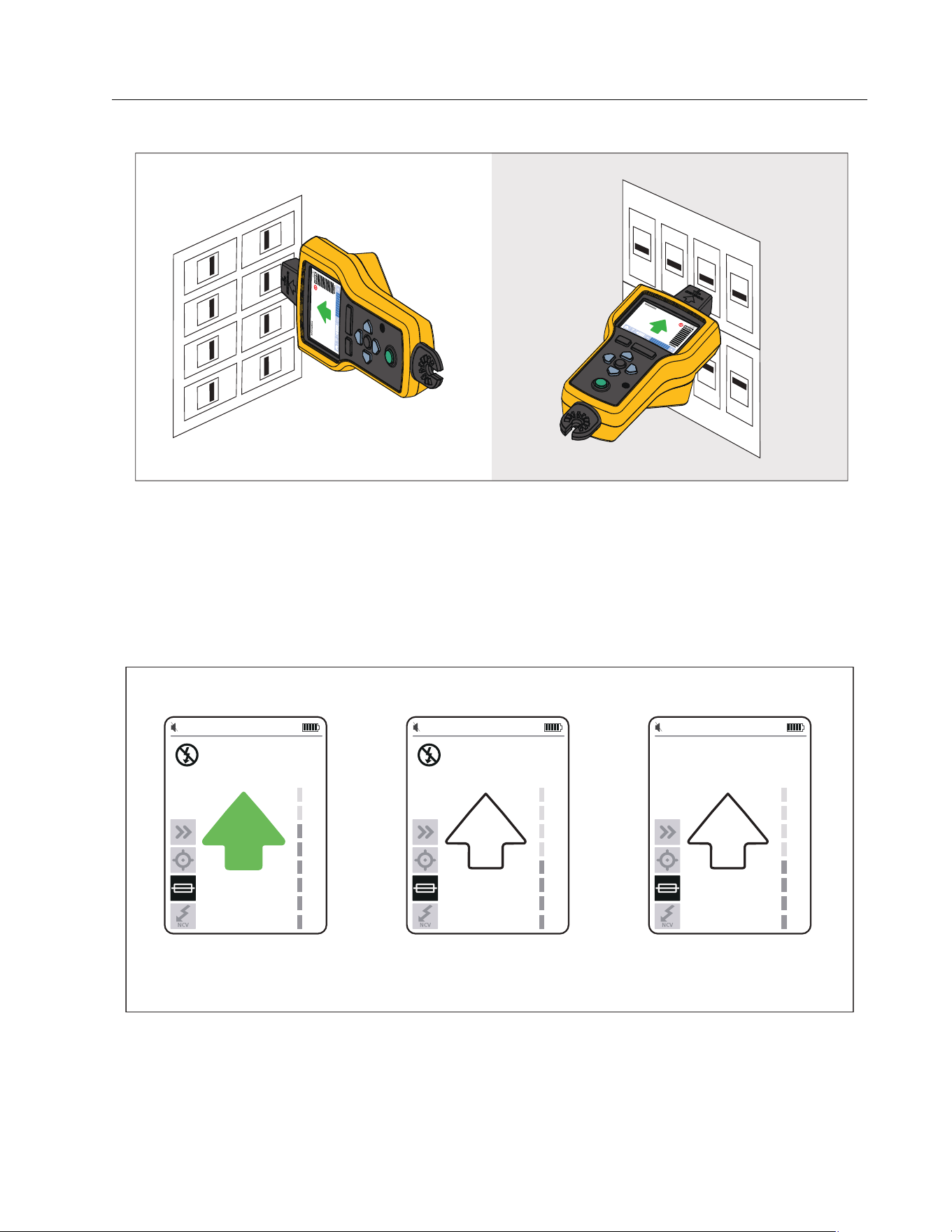
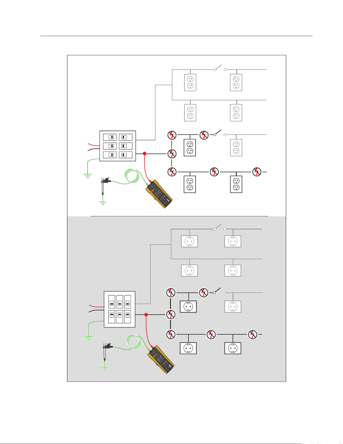
Map a Circuit
Use test leads or the Clamp to map a de-energized circuit. Use the Clamp to map an energized
circuit.
Te s t Le a d s
To use test leads to map a de-energized circuit:
1. Turn off the breaker or fuse.
2. Connect the Transmitter. See Figure 23.
3. On the Receiver, select tip sensor mode.
4. Scan the face plates of receptacles and wires towards the load with the tip sensor of the
Receiver.
The receptacles and loads that are connected to the breaker or fuse show a strong signal
on the Receiver.
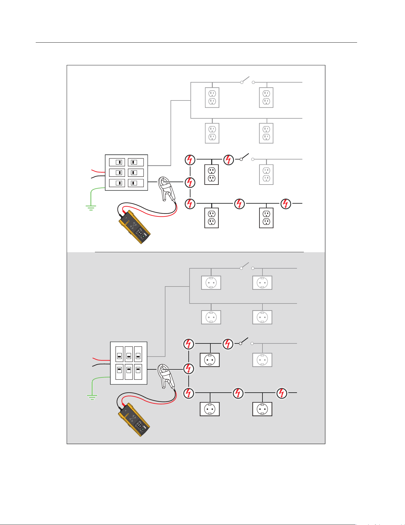
The Clamp
To use the Clamp to map an energized or de-energized circuit:
1. Connect the Clamp around the wire at the breaker or fuse panel. See Figure 24.
2. On the Receiver, select tip sensor mode.
3. Scan the face plates of receptacles and wires towards the load with the tip sensor of the
Receiver.
The receptacles and loads that are connected to the breaker or fuse show a strong signal
on the Receiver.
1.888.610.7664 sales@GlobalTestSupply.com
Fluke-Direct.com
Wire Tracer Receiver and Transmitter
Special Applications
39
Figure 23. Map a Circuit with Test Leads
2000T
TRANSMITT
ER
2000T
TRANSM
ITT
ER
1.888.610.7664 sales@GlobalTestSupply.com
Fluke-Direct.com
2052R/2062R/2000T
Users Manual
40
Figure 24. Map a Circuit with the Clamp
2000T
TRANSM
ITT
ER
2000T
TRANSM
ITTER
1.888.610.7664 sales@GlobalTestSupply.com
Fluke-Direct.com

Wire Tracer Receiver and Transmitter
Maintenance
41
Maintenance
The Product requires little maintenance.
Warning
To prevent possible electrical shock, fire, or personal injury:
Use only specified replacement parts.
Use only specified replacement fuses.
Have an approved technician repair the Product.
Do not use the Product if it is altered or damaged.
Examine the case before you use the Product. Look for cracks or missing plastic.
Carefully look at the insulation around the terminals.
Do not apply more than the rated voltage, between the terminals or between each
terminal and earth ground.
Batteries contain hazardous chemicals that can cause burns or explode. If
exposure to chemicals occurs, clean with water and get medical aid.
Repair the Product before use if the battery leaks.
Battery leakage may create a shock hazard or damage the Product.
Remove the batteries if the Product is not used for an extended period of time, or
if stored in temperatures above 50 °C. If the batteries are not removed, battery
leakage may result.
The battery door must be closed and locked before you operate the Product.
Be sure that the battery polarity is correct to prevent battery leakage.
Do not put battery cells and battery packs near heat or fire. Do not put in sunlight.
Remove all probes, test leads, and accessories before the battery door is opened.
Clean the Product
Periodically wipe the case with a damp cloth and mild detergent. Do not use abrasives or
solvents. Dirt or moisture in the terminals can affect readings.
1.888.610.7664 sales@GlobalTestSupply.com
Fluke-Direct.com
2052R/2062R/2000T
Users Manual
42
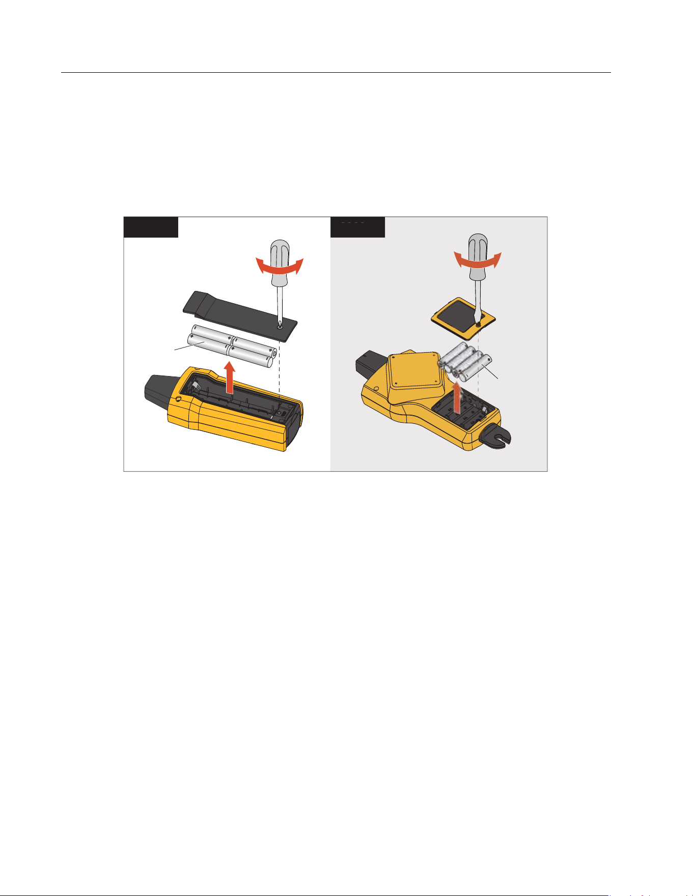
Receiver Battery Replacement
Use alkaline or rechargeable NiMH batteries. Batteries do not come installed in the Receiver.
To charge NiMH batteries, remove from the batteries from the Receiver.
To install or replace the batteries in the Receiver, turn off the Receiver and install new batteries
with the correct polarity. See Figure 25.
Figure 25. Receiver Battery Replacement
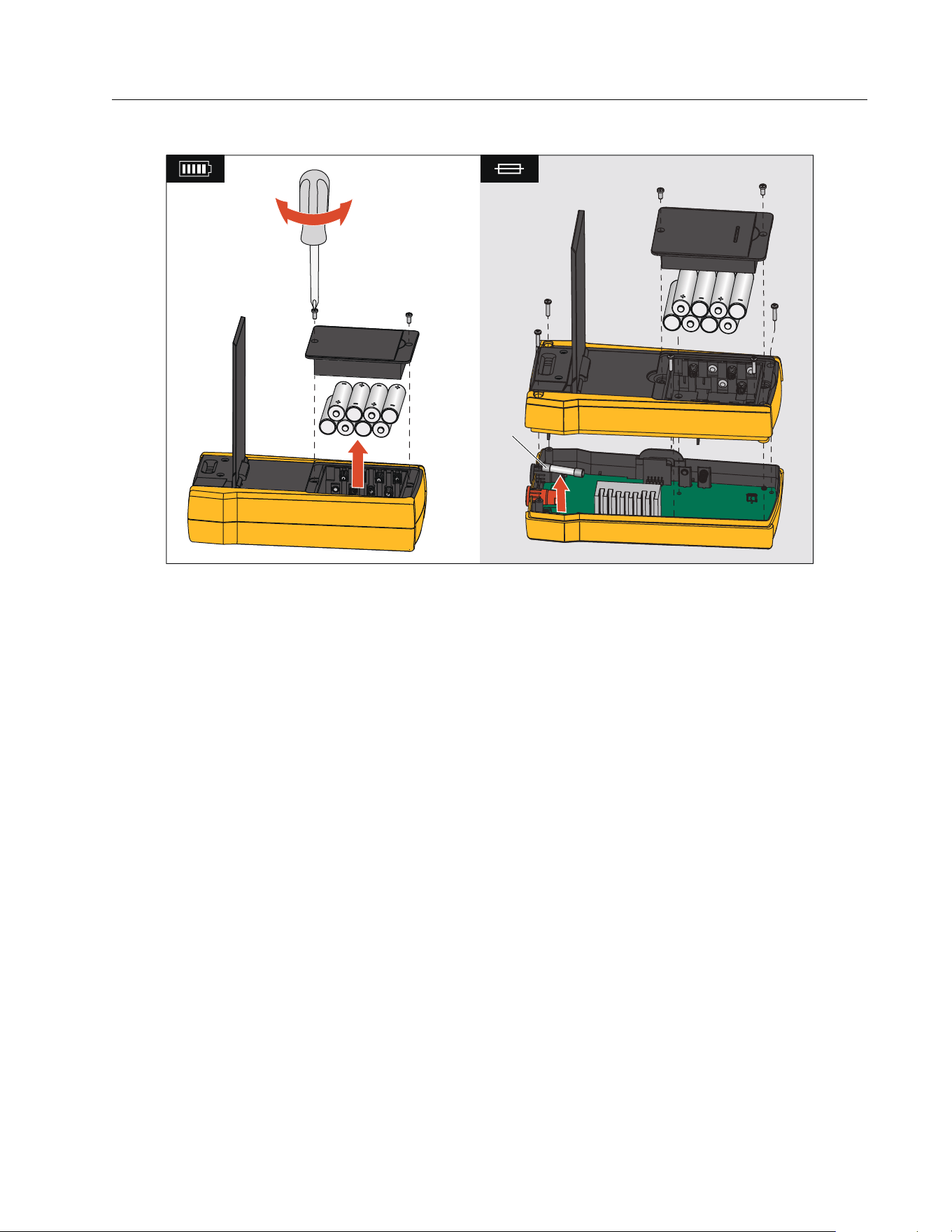
Transmitter Battery Replacement
Alkaline batteries ship with the Product. If desired, use NiMH rechargeable batteries in the
Transmitter. Batteries do not come installed in the Transmitter. To charge NiMH batteries,
remove the batteries from the Transmitter.
To install or replace the batteries in the Transmitter, turn off and disconnect the Transmitter
from the circuit and install new batteries with the correct polarity. See Figure 26. With new
batteries installed, set the battery type. See Battery Type Selection (2000T, 2052R).
4 AA
2062
R
4 AA
2052
R
4 AA
2062
R
1.888.610.7664 sales@GlobalTestSupply.com
Fluke-Direct.com
Wire Tracer Receiver and Transmitter
Maintenance
43
Figure 26. Transmitter Battery and Fuse Replacement
Battery Type Selection (2000T, 2052R)
If the battery type is not defined manually, the Product automatically sets the type to alkaline
or NiMH. Automatic battery type recognition draws more current and may be unreliable when
batteries do not contain an adequate charge. To increase the reliability of automatic battery
detection, use new batteries or charge NiMH batteries regularly. For best results, set the
battery type manually.
To manually set the battery type as alkaline:
1. Turn off the Product.
2. Push and hold the volume B button and simultaneously.
To manually set the battery type as NiMH:
1. Turn off the Product.
2. Push and hold the volume C button and simultaneously.
W
1.888.610.7664 sales@GlobalTestSupply.com
Fluke-Direct.com

2052R/2062R/2000T
Users Manual
44
Transmitter Fuse Replacement
To install or replace the fuse in the Transmitter (See Figure 26.):
1. Turn off and disconnect the Transmitter from the circuit.
2. Remove the tilt stand screw.
3. Remove the battery compartment screws, the battery cover, and batteries.
4. Remove the screws in the back cover.
5. Pull up on the back cover to remove the cover.
6. Remove the fuse from the fuse holder.
7. Insert the new fuse (1 A, 700 V, fast-acting, 6 mm x 32 mm, 50 kA interrupt rating) in th
e
fuse holder.
8. Replace and secure the back cover, the batteries, the battery cover, and the tilt stand.
Product Disposal
Dispose of the Product in a professional and environmentally sound manner:
Delete personal data on the Product before disposal.
Remove batteries that are not integrated into the electrical system before disposal and
dispose of batteries separately.
If this Product has an integral battery, put the entire Product in the electrical waste.
Specifications
For the complete product specifications, see our website.
1.888.610.7664 sales@GlobalTestSupply.com
Fluke-Direct.com