USER MANUAL
V210 CABLE TRACKER
www.vdiagtool.com

Safety Information
To ensure your safety and prevent damage to the device or vehicle,
please carefully read and follow all instructions in this manual before
use.
When operating the device, always verify proper testing procedures
and strictly adhere to the instructions provided. As automotive electri-
cal systems may vary, you must assess potential risks and ensure a
safe testing environment.
Always observe all safety warnings, use appropriate tools, and discon-
nect power sources when necessary. Improper operation may result in
personal injury, equipment damage, or voided warranty.
Safety Messages
Safety messages use standardized signal words to indicate hazard
levels and prevent injuries or equipment damage:
DANGER
Will result in death or serious injury if ignored
Indicates an immediately life-threatening hazard.
WARNING
Could result in death or serious injury if ignored
Indicates a potentially dangerous situation.
Safety Instructions
This manual covers known safety hazards, but cannot anticipate all
possible risks. You are responsible for ensuring safe operating condi-
tions and procedures.
DANGER
• Always ventilate the service area when engine is running or use
building exhaust removal system if available
• Carbon monoxide is odorless and deadly - can cause loss of
consciousness or death

WARNINGS
• Always keep a fire extinguisher suitable for gasoline, chemical, and
electrical fires nearby.
• Never operate or observe the tool while driving—distraction can
lead to fatal accidents.
• Keep clothing, hair, hands, tools, and test equipment away from
moving or hot engine parts.
• Perform automotive testing only in a safe, controlled environment.
• Ensure proper ventilation—exhaust gases are poisonous.
• Never connect or disconnect test equipment while the ignition is ON
or the engine is running.
• Place wheel chocks in front of drive wheels and never leave the
vehicle unattended during testing.
• Wear ANSI-approved safety eye protection at all times.
• Exercise extreme caution around ignition coils, distributor caps,
spark plugs, and wires—high voltage is present when the engine is
running.
• Before testing, ensure the transmission is in P (A/T) or Neutral (M/T)
and the parking brake is engaged.
• Keep the scan tool clean and dry; avoid contact with oil, water, or
grease. Clean only with a mild detergent and soft cloth.
• Do not modify, disassemble, or expose the tool to extreme tempera-
tures or moisture.
• This tool is not a substitute for professional diagnostic equip-
ment—use with caution.
• The manufacturer is not liable for damages caused by misuse, negli-
gence, or unauthorized modifications.
Legal Information
Trademarks
VDIAGTOOL is a registered trademark of Shenzhen VDIAGTOOL Tech-
nology Co., Ltd in the United States and other jurisdictions. All other
product names mentioned herein may be trademarks of their respec-
tive owners.
Copyright Information
© 2017 Shenzhen VDIAGTOOL Technology Co., Ltd. All rights
reserved.

No reproduction, distribution, or transmission of this manual is
permitted without express written authorization from VDIAGTOOL.
This prohibition applies to all forms of copying including electronic,
mechanical, photocopying, and recording.
Disclaimer & Liability Statement
Product Documentation Notice
All illustrations, specifications, and technical data in this manual are
for reference only and subject to change without notice.
For the latest documentation, visit:
https://www.vdiagtool.com/support/downloads
Limitation of Liability
VDIAGTOOL expressly disclaims all liability for:
• Any direct, indirect, incidental, or consequential damages
• Loss of profits or business interruption
• Product modifications or unauthorized use
This manual does not:
• Modify existing purchase/lease agreements
• Create additional liabilities for VDIAGTOOL
• Constitute additional product warranties
IMPORTANT:
Always consult this manual before operation, with special attention to
all safety warnings. VDIAGTOOL reserves the right to modify product
specifications at any time.
Product Support & Training Resources
Technical Support
• Official Website: www.vdiagtool.com
• Support Email: [email protected]
• US Hotline: +1-213-355-7171
• Online Form: https://www.vdiagtool.com/support/tech-support

Training Videos
Free product operation videos:
1. Visit Training Center:
https://www.vdiagtool.com/support/training-center
2. Select Circuit Testers category
3. Watch model-specific tutorials

V210 Cable Tracker
Contents
1. Product Overview..................................................................... 1
1.1 Specifications.......................................................................................... 1
1.2 Tool Description..................................................................................... 1
1.3 Included Parts List................................................................................. 3
1.4 Battery Replacement............................................................................ 3
1.4.1 V210 Transmitter Battery Replacement............................... 3
1.4.2 V210 Receiver Battery Replacement.................................... 3
2. How to Use the Probe.............................................................. 3
3. Setting the Sensitivity Level.................................................... 4
4. Product Features....................................................................... 4
4.1 Locating Short Circuit.......................................................................... 4
4.2 Locating Open Circuit.......................................................................... 5
4.3 Wire Tracing............................................................................................. 6
4.4 Wire Identification................................................................................. 8
4.5 General Tracing Procedures............................................................... 9
4.5.1 Working with Open Circuits.................................................... 9
4.5.2 Working with Short Circuits (and Tracing Circuits)...... 10
4.5.3 Some Circuit Characteristics that May Affect the Tracing
of a Wire............................................................................................................. 11
4.6 Special Tracing Procedures............................................................. 11
4.7 Wire Bundles and Conduits............................................................ 11
4.8 To increase the Pickup Range When Tracing Wires............... 12
4.9 Circuits with Multiple Loads and Branches............................... 13
5. Warranty.................................................................................. 14
6. Contact Us............................................................................... 14

1
V210 Cable Tracker
1. Product Overview
1.1 Specifications
V210 Transmitter
V210 Receiver
Operating Voltage
Working Current
Operating Temperature
Storage Temperature
Max Operating Relative Humidity
Max Storage Relative Humidity
Power Source
Dimensions (L × W × H)
Weight
Material
Probe Length
Power Source
Working Current
6V - 42V DC
0.2A - 0.5A
0°C to 60°C (32°F to 140°F)
-40°C to 70°C (-40°F to 185°F)
80%
50%
9V (Powered by 9V Battery)
73.6 × 61 × 22.15mm (2.89 × 2.40 × 0.87 in)
63g (0.138 lbs)
ABS
172mm (6.77 in)
9V (Powered by 9V Battery)
0.2A - 0.5A
Operating Temperature
Storage Temperature
Max Operating Relative Humidity
Max Storage Relative Humidity
Dimensions (L × W × H)
0°C to 60°C (32°F to 140°F)
-40°C to 70°C (-40°F to 185°F)
80%
50%
ABS
184 × 48 × 24mm (7.24 × 1.88 × 0.94 in)
84g (0.185 lbs)
Material
Weight
2
V210 Cable Tracker
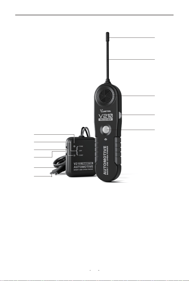
1.2 Tool Description
①Probe Sensor: Black cylinder to detect electromagnetic signal for
the V210 receiver.
②Probe: 6.7” long, flexible, built of coiled steel and equipped with a
sensor at the top to fit for congested or difficult areas.
③Speaker: Generates tone when signal is picked up by the V210
receiver.
④On/Off & Sensitivity Rotary Switch: Turn the switch clockwise to
power on the V210 receiver and increase sensitivity level; turn
anti-clockwise to decrease sensitivity level and power off.
⑤TEST Button: Press and hold TEST button to pick up audio signal.
⑥Red Test Lead: Red test lead of the V210 transmitter.
①
③
④
⑤
⑥
⑧
⑨
⑩
⑪
⑦
②

3
V210 Cable Tracker
⑦Black Test Lead: Black test lead of the V210 transmitter.
⑧Mode Switch: Mode switch of the V210 transmitter.
⑨CONT Mode: Switch to CONT mode to test continuity or short
circuit.
⑩Power Off: Switch to power off the V210 transmitter.
⑪TONE Mode: Switch to TONE mode to test open circuit or tracing
wire.
1.3 Included Parts List
1.4 Battery Replacement
1.4.1 V210 Transmitter Battery Replacement
Open the battery cover at the back of the V210 transmitter, replace
the exhausted battery with a new one of 9V (6F22) and reinstall the
battery cover.
1.4.2 V210 Receiver Battery Replacement
Open the battery cover at the back of the V210 receiver, replace the
exhausted battery with a new one of 9V (6F22) and reinstall the
battery cover.
2. How to Use the Probe
The probe of the V210 receiver is built of coiled steel equipped with
a sensor (black cylinder), and can be bent as needed, in order to
reach wires in congested or difficult areas. Depending on the circuit
characteristics and the sensitivity setting, the probe’s sensor will
pick-up the signal from the wire in a wide range of positions.
Pa Quanlity
V210 Transmitter 1
V210 Receiver 1
User Manual 1
Packing Box 1

4
V210 Cable Tracker
However, for the best possible range, the V210 receiver’s sensor
(black cylinder) should be positioned perpendicular (at 90°) to the
wire being traced and either above or below it, as shown below:
3. Setting the Sensitivity Level
VDIAGTOOL V210 receiver comes with rotary switch dial to adjust
sensitivity level easily which allows technician to choose the degree
of sensitivity most suitable to the particular detection being
performed.
To turn on V210 receiver or increase sensitivity level:
Switch the rotary switch dial clockwise to turn on the V210 receiver
and increase sensitivity level;
To turn off V210 receiver or decrease sensitivity level:
Switch the rotary switch dial anti-clockwise to decrease sensitivity
level, and switch it off until you hear a click.
4. Product Features
4.1 Locating Short Circuit
Observe the limits and safety precautions at all times.
(1) Disconnect the power that is connected to the wire being tested,
and remove all the loads(for example, remove light bulb from the
wire).
(2) Switch the V210 transmitter to “CONT” position, and connect the
test leads to the wire.
(3) When the resistance is less than 10k ohm, the LED indicator at the
“CONT” position lights up in green and it means the wire is shorted.
CORRECT
Sensor
Cable
90°
INCORRECT
Sensor
Cable
5
V210 Cable Tracker
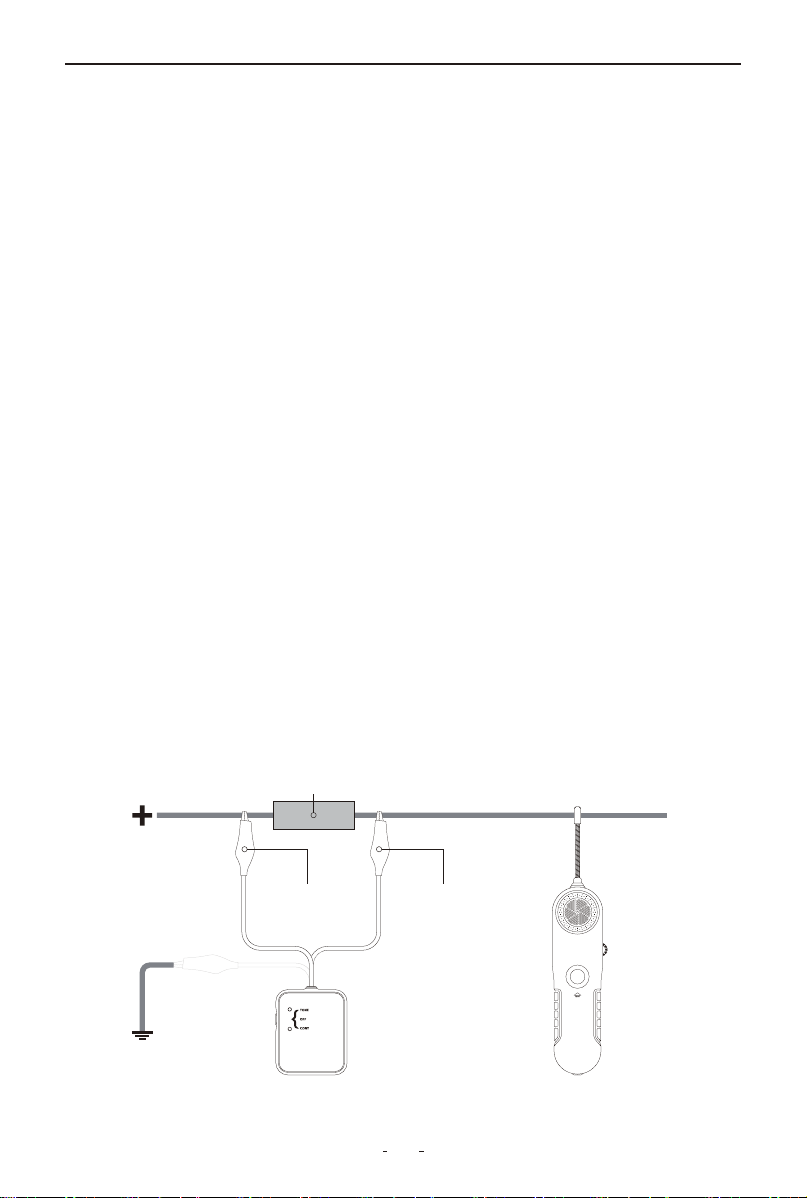
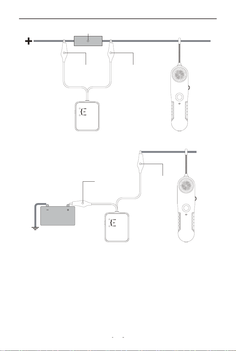
4.2 Locating Open Circuit
(1) Set the V210 transmitter to “TONE”, and the red LED indicator
lights up. If the red LED indicator does not light up, please check the
battery.
(2) Switch on the V210 receiver and set its rotary switch to the
middle position. Press and hold the “TEST” button and move the
probe sensor close to the test leads of the transmitter, the V210
receiver receives signal and generates a tone. That means the tool
works correctly.
(3) Connects the black test lead to the circuit’s positive supply (or to
the negative supply for vehicles with positive supply connected to
chassis). Connect the red test lead to the wire being tested. A fuse
socket (with blown fuse removed), a connector provides a conve-
nient hook up.
(4) Switch on the V210 receiver and set the rotary switch to the
middle position. Press and hold the “TEST” button and sweep the
wire slowly with the probe sensor, ensuring the probe is perpendicu-
lar and above or below the wire being traced and as close as possi-
ble to it.
(5) Follow the wire or check it at different points, starting from the
transmitter and moving towards the load (accessory, light etc),
observing the positioning of the probe as indicated above.
(6) Continue this procedure when the tone indicates the integrity of
the circuit. When the tone stops, it means the probe has just passed
the open point, breaker or bad connection in the circuit.
Fuse Socket or Connector
V210 Receiver
Black Negative Wire Red Positive Wire
V210 Transmitter
OR

6
V210 Cable Tracker
(7) If it’s difficult or unable to pick up any signal, please increase the
sensitivity and try again.
(8) Double check by positioning the probe before and after the
suspected point. If the open circuit point has been found, the tone
will show circuit integrity on one side, and not on the other. At this
point, where the audio signal stops, you have found the open circuit.
(9) When you have finished locating the open circuit point, discon-
nect the test leads’ connection, set the transmitter to “OFF” position
and loose the “TEST” button.
4.3 Wire Tracing
Note: Observe the limits and safety precautions at all times.
(1) Set the switch of the V210 transmitter to “TONE”, the red LED of
the transmitter lights up. If the red LED does not light up, please
check the battery.
(2) Switch on the V210 receiver, set the rotary switch to the middle
position. Press and hold “TEST” button, meanwhile move the probe
sensor close to the test lead of the transmitter. Receiver receives the
signal and generates tone. If so, it means the unit works correctly.
(3) Connect the black test lead to the circuit positive supply ( or to
the negative for the vehicles with positive supply connected to chas-
sis). Connect the red test lead to the wire being traced. A fuse socket
(with blown fuse removed), a connector provides a convenient
hook-up.
(4) Set the switch of the V210 receiver to the middle position. Press
and hold the “TEST” button, meanwhile move the probe sensor as
close as possible to the wire to be traced. The probe sensor should
be placed perpendicular(90°) to the wire and either above or below
it.
(5) The V210 receiver gives audio signal. Trace the wire by following
the tone of the receiver. If you move the probe sensor away from the
wire, the tone will decrease and then disappear.
(6) If the V210 receiver is difficult or impossible to pick up any signal,
please increase the sensitivity level and try again, and double check
the suspected points.
7
V210 Cable Tracker
(7) When you have finished tracing the wire, disconnect the test
leads, set the V210 transmitter to “OFF” position and loose the
“TEST” button.
For step by step directions: please refer to point 4.1 Locating Short
Circuits, for some hints and specific differences, refer to the notes
below:
The type and size of load connected to the circuit (impedance or
resistance to ground) determines the amount of current allowed to
Fuse Socket or Connector
V210 Receiver
Black Negative Wire Red Positive Wire
V210 Transmitter
V210 Receiver
Black Negative
Wire
Red Positive
Wire
V210 Transmitter
8
V210 Cable Tracker
4.4 Wire Identification
Note: Observe the limits and safety precautions at all times.
(1) Set the switch of the V210 transmitter to “TONE”, the red LED
indicator will light up. If the red LED does not light up, please check
the battery.
flow in the circuit. Small loads (low voltage lamps, electronic
systems, etc.) will reduce the range of the V210 receiver accordingly.
In cases where the full range of the V210 receiver is required to
follow the wire, it may prove advantageous to use one of the two
methods described below:
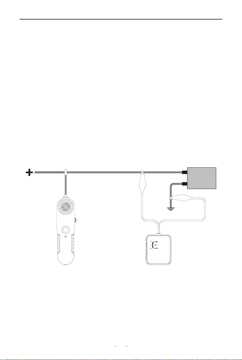
• Tracing wires downstream (from supply to load): replacing the
load for a full short circuit allows the V210 receiver to work at its
maximum capabilities. Before proceeding, remove all electrical
power from the circuit, connect the V210 transmitter in series with
the wire to trace, short circuit the load to ground, then reconnect
power and follow instructions in section 4.1 Locating Short Circuits.
• Tracing wires upstream (from load to supply): If more conve-
nient, wires can also be traced the other way around, by replacing
the load with the V210 transmitter. To do this, first remove power
from the circuit, disconnect the load and connect the V210 transmit-
ter in its place. Apply power to the circuit and follow instructions in
section 1.8 Locating Short Circuits.
V210 Receiver V210 Transmitter

9
V210 Cable Tracker
(2) Switch on the V210 receiver, set the rotary switch in middle posi-
tion. Press and hold “TEST” button, meanwhile move the probe
sensor close to the test lead of the transmitter.
• For identifying wires with load connected: Connect the V210
transmitter as described in section 2.8 Locating Short Circuits to the
circuit to be identified, then proceed to scan all suspected wiring
with the V210 receiver probe sensor until the tone is at its maximum.
In the case of tightly packed wires (bundles, conduits, etc.), it may be
necessary to spread these apart to facilitate the identification
process of a particular wire.
• For identifying wires without load connected: Connect the V210
transmitter as described in section 4.2 Locating Open Circuits to the
circuit to be identified, then proceed to scan all suspected wiring
with the V210 receiver probe sensor, until the tone is at its maxi-
mum. In the case of tightly packed wires (bundles, conduits, etc.), it
may be necessary to spread these apart to facilitate the identifica-
tion process of a particular wire.
4.5 General Tracing Procedures
Short and open circuit operation – Differences:
The V210 uses two different types of signals to trace either short or
open circuits. Understanding its differences, as explained in the
following paragraphs will allow you to make the most effective use
of this versatile tool.
4.5.1 Working with Open Circuits
On detection of an open circuit, the V210 transmitter injects a
special radio signal into the circuit, which can be picked up by the
V210 receiver probe sensor.
When tracing an open circuit, keep in mind that RF (radio frequency)
signals injected in the faulty wire being traced, will be easily
absorbed by any other conductor nearby. (e.g.: other wires, metal
frames). The effect of this absorption may vary from a reduction in
the V210 receiver’s range, to a total shielding of the signal with no
detection being possible at all.
10
In order to avoid confusing a shielded portion of the faulty wire with
the actual fault on it, the circuit should be checked on in several
places to confirm that no signal is detected on the other side of the
suspected faulty section.
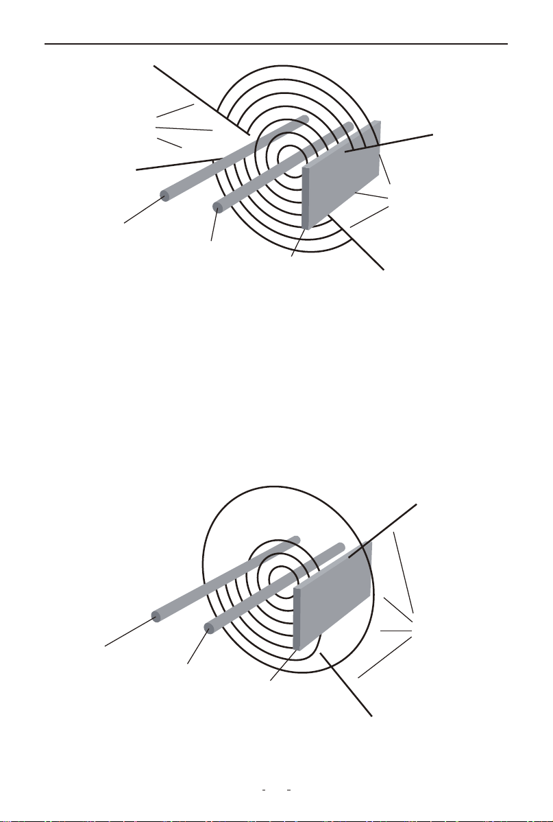
4.5.2 Working with Short Circuits (and Tracing Circuits)
When the V210 transmitter detects a short circuit (or closed circuit),
it injects pulses of electrical current in the wires, which generate
magnetic fields. Unlike radio signals, magnetic fields are not easily
absorbed by nearby conductors and therefore can be picked up by
the V210 receiver probe sensor in a wider range of situations.
V210 Cable Tracker
Weakened
or no
signal
area
Weakened
or no
signal
area
Other Wire
Traced wire
Steel Pa
Weakened
signal
area
Other Wire
Traced wire
Steel Pa

11
V210 Cable Tracker
4.5.3 Some Circuit Characteristics that May Affect the Tracing of
a Wire
• Electromagnetic loop size and geometry, etc. may affect the range
of the V210 receiver. For example for circuits in which the live and
ground (return) wire run parallel and close to each other in the same
circuit, the two magnetic fields interaction may weaken the signal,
thereby reducing the V210 receiver range.
• Wires enclosed or tightly lining the metal frame or body of the
vehicle, (i.e.: door frames), have the same effects as having the live
and ground wires running in parallel in the same circuit since, the
metal frame or vehicle body will be acting as a ground wire. Another
unfavorable factor may be due to the channeling effect steel parts
have on magnetic fields. These two cases, individually or combined,
will reduce and sometimes impede the wire sections affected.
Hint: Whenever possible the short circuit mode of operation should
be used, because it provides with the best tracing capabilities.
4.6 Special Tracing Procedures
In all cases, first set the V210 receiver at a lower sensitivity level and
increase it as necessary. Proceed as indicated in the sections of this
User’s Manual applicable to your situation.
• Always after locating a probable fault area, verify several points in
the wires on both sides (before and after) the suspected area. The
signal should be present at only one side of the fault (open or short).
This procedure will help avoid confusing a signal loss with the actual
trouble point.
4.7 Wire Bundles and Conduits
Special care should be given in the case of tracing a wire inside a
bundle or conduit when there is a split. In this case it may be possi-
ble to follow the wrong branch for a short distance and still receive
a positive audio/ visual indication.
• To avoid following the wrong path, which could happen if the V210
receiver probe sensor picks up the signal from the other nearby
branch of the circuit, the branches should be swept maintaining the
probe sensor outside the apex area between the split, as shown
below:

12
V210 Cable Tracker
• Careful attention should be paid to the beeping and flashing speed
of the V210 receiver unit indicators, as these provide the necessary
feedback to evaluate the proximity of the probe sensor to the wire
being traced.
4.8 To increase the Pickup Range When Tracing Wires
When tracing or identifying wires connected to a lightly loaded
circuit (low currents), pickup range is reduced significantly. A possi-
ble solution is, after connecting the V210 transmitter in series with
the circuit to trace, is to replace the load (light bulb, module, etc.)
with a direct connection to ground. This allows the V210 transmitter
to inject a more powerful signal which is easier to detect.
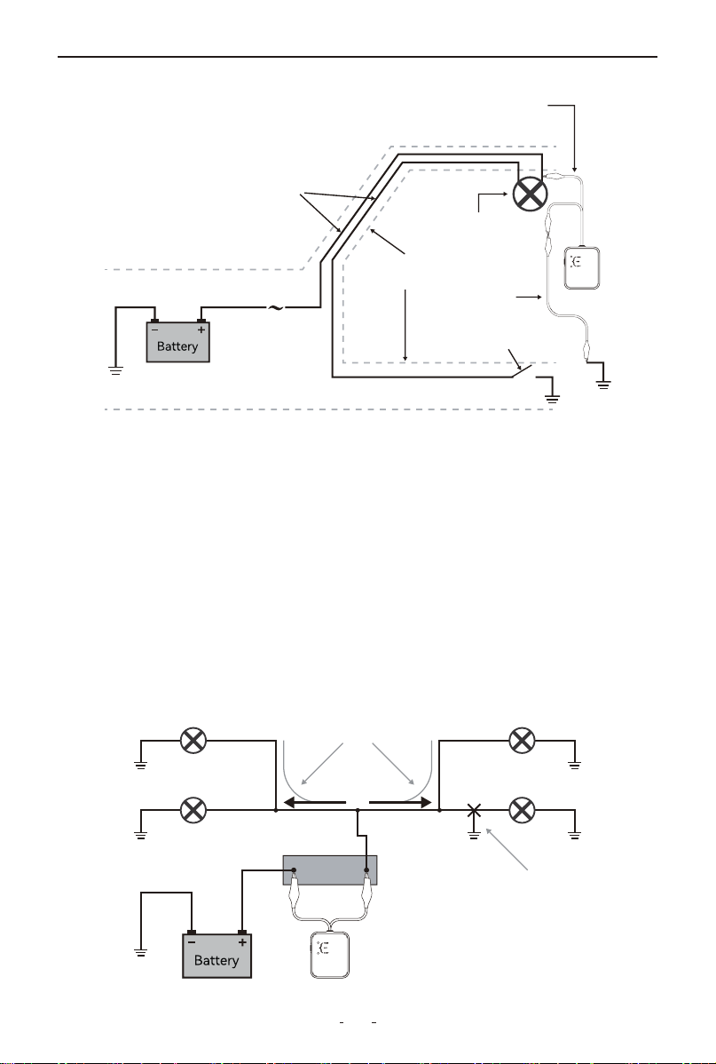
• For the cases in which it is suspected the layout of the wires is the
cause of a very difficult to pick up or weak signal, a dramatic increase
of the range can be accomplished by “spreading” the circuit.
• The spreading the circuit is achieved by connecting a jumper wire
between the live wire (preferably at a termination point in the circuit
such as a light bulb socket, switch, etc.), and a ground point some-
where else in the vehicle.
This last method should be used only as “last resource” and with the
V210 receiver set to a lower sensitivity, as it could make the
pinpointing of the precise location more difficult due to the much
increased range.
Tracing inside this
area may generate
misleading results
Trace with probe
on this side
Wire bundle
or conduit
Trace with probe
on this side
13
V210 Cable Tracker
• Always verify that the V210 transmitter is connected in series with
the circuit being tested and that its red indicator light is on, as this
confirms a proper connection and will limit the amount of current
flowing in the circuit.
4.9 Circuits with Multiple Loads and Branches
When tracing circuits connected to, or which are powering multiple
loads and/or branches, and when these circuits are active or live, the
bulk of the current injected into the circuit by the V210 transmitter
will be directed to the shorted branch of the circuit. However smaller
amounts of current (or stray currents) will flow to the other branches
as long these provide a path to ground (i.e. close the circuit).
Light
Jumper
Wire
Door switch
Wires shielded
by door frame
Fuse
Box
Positive (Live) and ground
wires running parallel
to each other
Connection of the V210
transmitter at the load using
a jumper wire to ground
Light Bulb
Light Bulb
Light Bulb
Current Flow
Sho Circult
Fuse Socket
Light Bulb

14
V210 Cable Tracker
• These stray currents present in the non-shorted branches of the
circuit, and depending on the circuit configuration and physical
layout of the wires, could be picked up by the V210 receiver, making
the tracing procedures confusing, and even misleading.
• The simplest and most effective way to deal with these cases, is to
disconnect or remove all the loads from the circuit being traced (i.e.
removing light bulbs in example shown above.)
5. Warranty
Limited Three Years Warranty
VDIAGTOOL warrants the V210 product against defects in materials
and workmanship for thirty-six (36) months from the date of delivery
to the original purchaser for commercial or business use. This
warranty does not cover damage resulting from misuse, unautho-
rized modification, improper maintenance, or operation outside
specified conditions. VDIAGTOOL's sole liability shall be limited to
repair or replacement of defective components at its discretion.
Consequential, incidental, or other damages are expressly excluded.
Some jurisdictions may not permit certain limitations of liability.
6. Contact Us
Warranty & Support
Email: [email protected]
Website: www.vdiagtool.com
For wholesale business or become our distributors:
Email: [email protected]
Invent with us, test products before they hit market, help us
make better products for everyone:
Email: [email protected]
Create social media content, post online and help our communi-
ty:
Email: [email protected]

15
V210 Cable Tracker
Follow Us on Social Media
Facebook Page: Search for "vdiagtool"
Facebook User Group: Search for "VDIAGTOOL OFFICIAL User
Group"
Instagram: Search for "vdiagtool_official"
TikTok: Search for "vdiagtool_us"
YouTube: Search for "Vdiagtool Official"