USER MANUAL
P60 AUTOMOTIVE TEST LIGHT
www.vdiagtool.com

Safety Information
To ensure your safety and prevent damage to the device or vehicle,
please carefully read and follow all instructions in this manual before
use.
When operating the device, always verify proper testing procedures
and strictly adhere to the instructions provided. As automotive electri-
cal systems may vary, you must assess potential risks and ensure a
safe testing environment.
Always observe all safety warnings, use appropriate tools, and discon-
nect power sources when necessary. Improper operation may result in
personal injury, equipment damage, or voided warranty.
Safety Messages
Safety messages use standardized signal words to indicate hazard
levels and prevent injuries or equipment damage:
DANGER
Will result in death or serious injury if ignored
Indicates an immediately life-threatening hazard.
WARNING
Could result in death or serious injury if ignored
Indicates a potentially dangerous situation.
Safety Instructions
This manual covers known safety hazards, but cannot anticipate all
possible risks. You are responsible for ensuring safe operating condi-
tions and procedures.
DANGER
• Always ventilate the service area when engine is running or use
building exhaust removal system if available
• Carbon monoxide is odorless and deadly - can cause loss of
consciousness or death

WARNINGS
To avoid personal injury and prevent damage to the vehicle or the
VDIAGTOOL P60, please read this manual carefully and observe the
following safety precautions at all times:
• Only use the P60 for testing DC 3V–70V automotive electrical
circuits.
• Do not use the tool on AC systems or circuits exceeding the speci-
fied voltage range.
• Do not test airbag (SRS) wiring - risk of accidental deployment.
• Always disconnect the power source or turn off the ignition before
connecting or disconnecting the test tool.
• Keep clear of moving engine components and hot surfaces during
testing.
• Do not use in wet/damp conditions, as moisture may cause short
circuits or inaccurate readings
• Operate the vehicle in a well-ventilated area—exhaust gases are
toxic.
• Wear safety goggles and protective clothing during vehicle mainte-
nance.
• Do not operate the tool while driving. Using test tools while the
vehicle is in motion is dangerous.
• Ensure the vehicle is in Park (P) or Neutral (N) and the parking brake
is engaged before testing.
• Keep the test probe, alligator clip, and cable away from rotating
belts, fans, or pulleys.
• Never attempt to modify the tool or open the internal housing.
• Store the tool in a cool, dry place away from oil, moisture, and
extreme temperatu res.
• Clean the tool only with a soft cloth and mild detergent—never
immerse in liquid.
• The manufacturer is not responsible for damage caused by misuse,
modification, or testing beyond rated specifications.
Legal Information
Trademarks
VDIAGTOOL is a registered trademark of Shenzhen VDIAGTOOL Tech-
nology Co., Ltd in the United States and other jurisdictions. All other
product names mentioned herein may be trademarks of their respec-

tive owners.
Copyright Information
©2017 Shenzhen VDIAGTOOL Technology Co., Ltd. All rights reserved.
No reproduction, distribution, or transmission of this manual is
permitted without express written authorization from VDIAGTOOL.
This prohibition applies to all forms of copying including electronic,
mechanical, photocopying, and recording.
Disclaimer & Liability Statement
Product Documentation Notice
All illustrations, specifications, and technical data in this manual are
for reference only and subject to change without notice.
For the latest documentation, visit:
https://www.vdiagtool.com/support/downloads
Limitation of Liability
VDIAGTOOL expressly disclaims all liability for:
• Any direct, indirect, incidental, or consequential damages
• Loss of profits or business interruption
• Product modifications or unauthorized use
This manual does not:
• Modify existing purchase/lease agreements
• Create additional liabilities for VDIAGTOOL
• Constitute additional product warranties
IMPORTANT:
Always consult this manual before operation, with special attention to
all safety warnings. VDIAGTOOL reserves the right to modify product
specifications at any time.
Product Support & Training Resources
Technical Support
• Official Website: www.vdiagtool.com
• Support Email: [email protected]

• US Hotline: +1-213-355-7171
• Online Form: https://www.vdiagtool.com/support/tech-support
Training Videos
Free product operation videos:
1. Visit Training Center:
https://www.vdiagtool.com/support/training-center
2. Select Circuit Testers category
3. Watch model-specific tutorials

Contents
1. Product Introduction.............................................................1
1.1 Product Overview ...............................................................................2
1.2 Technical Specifications....................................................................3
2. Operating Instructions ..........................................................3
2.1 Self-Test..................................................................................................3
2.2 Step-by-Step Usage Instructions..................................................3
2.3 Voltage Detection...............................................................................4
2.4 Continuity Testing...............................................................................4
2.5 Polarity Identification ........................................................................4
2.6 Display and Indicator Meanings ...................................................4
2.7 Overvoltage Protection / OL Indicator.......................................5
3. Practical Applications............................................................5
3.1 Car Battery Testing .............................................................................5
3.2 Fuse and Circuit Check .....................................................................5
3.3 Light Socket and Relay Testing......................................................5
3.4 Ground Detection...............................................................................6
4. Maintenance & Storage ........................................................6
5. Troubleshooting Guide..........................................................6
6. Warranty .................................................................................7
7. Contact Us...............................................................................8

1
1. Product Introduction
The VDIAGTOOL P60 is a professional-grade test light designed for
quick and accurate diagnostics in 3V-70V DC electrical systems,
making it ideal for cars, motorcycles, trucks, and trailers. Unlike most
testers limited to 6V-24V systems, the P40's wide voltage range
provides superior versatility, especially for heavy-duty vehicles.
Featuring a dual-display system, the P60 combines a bright LED
indicator for instant power detection with a digital readout that
shows exact voltage values (e.g., "12.6V")—eliminating the guess-
work of traditional test lights that only provide on/off indications. Its
118-inch (3m) extended spring wire offers 30% more reach than
standard testers, allowing easy access to tight spaces like fuse boxes
and engine compartments.
Key Features:
• 3-in-1 Functionality – Voltage detection, continuity testing, and
polarity identification
• Industrial-Grade Durability – Stainless steel probe tip, flame-re-
tardant housing, and overload protection
• Non-Slip Grip – Ensures safe operation even in oily or messy envi-
ronments
• Precision Diagnostics – Digital voltage display prevents misdiag-
nosis
Common Applications:
• Quickly detect voltage
• Quickly check fuses without removal
• Diagnose battery and alternator issues
• Troubleshoot wiring breaks in all kinds of vehicles
• Test trailer lighting circuits
Compared to basic LED-only test lights, the P60 provides accurate
numerical readings for reliable diagnostics. Whether you're a profes-
sional technician or a DIY enthusiast, this all-in-one tester delivers
professional performance with enhanced durability and functional-
ity—outperforming most competitors in precision, build quality, and
versatility.
P60 TEST LIGHT
2
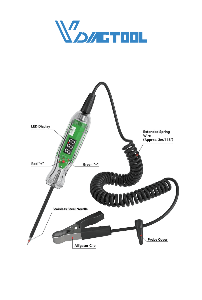
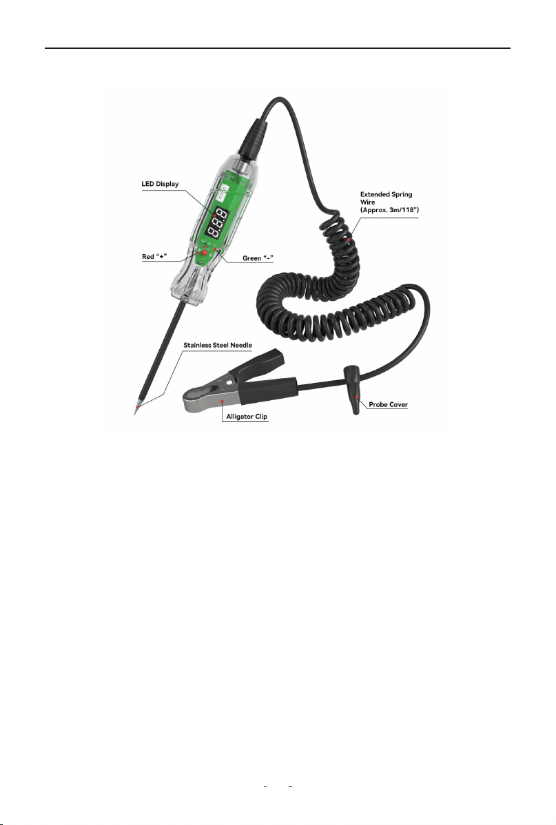
1.1 Product Overview
• LED Display:
Displays voltage readings or circuit status, helping users detect live
circuits.
• Red “+” / Green “-”:
Acts as a polarity indicator—red (“+”) indicates a positive charge,
while green (“-”) indicates a negative charge, assisting in correct
circuit identification.
• Extended Spring Wire (Approx. 3m/118"):
A highly flexible cable providing exceptional reach (approximately 3
meters/118 inches) for convenient probing while ensuring reliable
connection between the test probe and alligator clip.
• Probe Cover:
Protects the metal tip of the test probe, preventing accidental contact
or short circuits, and may provide insulation for safety.
• Alligator Clip:
Used as a grounding clip, attaching to a metal ground point (e.g.,
chassis or negative terminal) to complete the circuit during testing.
P60 TEST LIGHT

3
• Stainless Steel Needle:
The sharp test probe tip, made of durable stainless steel, directly
touches wires, fuses, or terminals to detect voltage or continuity.
1.2 Technical Specifications
2. Operating Instructions
This section explains how to safely and effectively use your VDIAG-
TOOL P40 Test Light for various testing scenarios.
2.1 Self-Test
Before use, verify proper function by testing on a known 3-70V DC
source - clip to ground (-) and probe to positive (+); the LED should
light red and display the correct voltage.
2.2 Step-by-Step Usage Instructions
1. Connect the Alligator Clip
- Attach the clip securely to a known ground point, such as the
battery negative terminal or an unpainted metal part of the chassis.
2. Activate the Circuit
- Turn the vehicle's ignition key to ON if the circuit you’re testing
requires it to be live.
3. Touch the Probe to the Test Point
- Place the stainless steel tip on the point you want to test—fuse
terminal, wire, bulb socket, relay pin, etc.
4. Read the Result
Voltage Range 3V – 70V DC
Display Type Digital LED
Accuracy ±0.3V
Resolution 0.1V
Cable Length Approx. 3 meters (118 inches)
Power Source No external battery required
Operating Temperature 0°C to 50°C (32°F to 122°F)
Applications Battery, fuse, light, relay, wiring check
Backlight
LED backlight for improved
visibility in low-light environments
P60 TEST LIGHT

4
- check the voltage displayed and observe whether the light illumi-
nates.
2.3 Voltage Detection
- When the probe touches a live (powered) wire or contact, the test
light will illuminate and the digital screen will display the voltage.
- If there is no light or the display shows 0.0V, the circuit may simply
be unpowered or not properly connected—this does not necessarily
mean the device is faulty.
2.4 Continuity Testing
- To check for continuity (unbroken connection in a wire or circuit),
touch both ends of the wire or circuit component:
1. One end connects to ground via the clip.
2. Touch the other end with the probe.
- If the circuit is complete, the light will turn on and the display will
show voltage from the connected source.
Important: Continuity tests should only be performed without
power applied to the circuit.
2.5 Polarity Identification
For models with polarity detection, the device distinguishes between
positive and negative voltage:
- A “+” symbol and red light may indicate positive polarity.
- A “–” symbol and green light may indicate negative polarity.
This helps ensure correct wire connection, especially in DC applica-
tions.
2.6 Display and Indicator Meanings
The number shown on the display is the measured voltage at the
test point.
If the screen flashes or shows unstable readings, this may indicate a
poor connection or an intermittent circuit fault.
If the LED indicator does not light up and the display shows 0.0V, it
means no voltage is detected.
P60 TEST LIGHT

5
2.7 Overvoltage Protection / OL Indicator
If the voltage exceeds the supported range, the screen may display
"OL" to indicate overvoltage.
If "OL" appears, stop testing immediately and disconnect the device.
This may indicate a dangerously high voltage.
3. Practical Applications
These are typical automotive use cases for the VDIAGTOOL P60 Test
Light:
3.1 Car Battery Testing
Purpose: Check the voltage output of the vehicle battery.
How to do it:
1. Connect the alligator clip to the battery negative terminal.
2. Touch the probe to the positive terminal.
3. Read the voltage:
- ~12.6V = fully charged
- <12.0V = needs charging
- Engine running: 13.5–14.7V indicates alternator is working
3.2 Fuse and Circuit Check
Purpose: Identify blown fuses or dead circuits.
How to do it:
1. With ignition ON, probe both ends of the fuse.
2. If only one side shows voltage, the fuse is blown.
3. You can also trace voltage along a circuit to locate a break.
3.3 Light Socket and Relay Testing
Purpose: Diagnose lighting issues or test relay power pins.
How to do it:
1. Probe inside light bulb sockets to see if voltage reaches the termi-
nals.
2. For relays, use the tester to check power and ground pins during
key-on status.
P60 TEST LIGHT

6
3. Helps determine whether the bulb, relay, or wiring is at fault.
3.4 Ground Detection
Purpose: Ensure a component has a reliable connection to chassis
ground.
How to do it:
1. Connect the clip to battery positive.
2. Use the probe to touch the suspected ground point.
3. If the test light turns on, that point is correctly grounded.
4. Maintenance & Storage
• Keep the probe clean and dry.
• Do not pull the cable sharply.
• Store in a dry, cool place.
• Avoid dropping or heavy impact.
5. Troubleshooting Guide
(1) No Power (LED/Display Off)
• Possible Causes:
- Poor ground connection
- Tested circuit has no power
• Solutions:
- Reattach ground clip to a clean, unpainted metal surface
- Verify circuit power using a known live source (e.g., battery posi-
tive terminal)
(2) Display Shows "0.0V" on Live Circuit
• Possible Causes:
- Poor probe contact
- Circuit voltage below 3V (out of range)
• Solutions:
- Scrape probe tip on contact point to remove oxidation
- Use a multimeter for voltages under 3V
P60 TEST LIGHT

7
(3) "OL" (Overload) Warning
• Possible Causes:
- Voltage exceeds 70V DC
- Short circuit in tested system
• Solutions:
- Immediately disconnect and check system voltage
- Never use on AC or high-voltage circuits
(4) Flickering Display
• Possible Causes:
- Loose wire in probe/cable
- Intermittent circuit fault
• Solutions:
- Inspect cable for damage (kinks/frays)
- Test a stable circuit to confirm
(5) Polarity Indicators Incorrect
• Possible Cause:
- Reverse connection (clip to +, probe to -)
• Solution:
- Reconnect properly: clip to ground (–), probe to positive (+)
(6) Probe Heats Up
• Possible Causes:
- Sustained high-current draw
- Poor contact causing arcing
• Solutions:
- Avoid prolonged contact with high-amperage circuits
- Clean probe tip regularly
6. Warranty
Limited Three Years Warranty
VDIAGTOOL warrants the P60 product against defects in materials
and workmanship for thirty-six (36) months from the date of deliv-
ery to the original purchaser for commercial or business use. This
warranty does not cover damage resulting from misuse, unautho-
rized modification, improper maintenance, or operation outside
P60 TEST LIGHT

8
specified conditions. VDIAGTOOL's sole liability shall be limited to
repair or replacement of defective components at its discretion.
Consequential, incidental, or other damages are expressly excluded.
Some jurisdictions may not permit certain limitations of liability.
7. Contact Us
Warranty & Support
Email: [email protected]
Website: www.vdiagtool.com
For wholesale business or become our distributors:
Email: [email protected]
Invent with us, test products before they hit market, help us
make better products for everyone:
Email: [email protected]
Create social media content, post online and help our communi-
ty:
Email: [email protected]
Follow Us on Social Media
Facebook Page: Search for "vdiagtool"
Facebook User Group: Search for "VDIAGTOOL OFFICIAL User
Group"
Instagram: Search for "vdiagtool_official"
TikTok: Search for "vdiagtool_us"
YouTube: Search for "Vdiagtool Official"
P60 TEST LIGHT