Vehicle Circuit Probe

2. USING THE TEST TOOL
2.1 SPECIFICATIONS
2.2 TOOL DESCRIPTION
2.3 PARTS LIST
2.4 GENERAL DESCRIPTION
2.5 POWER
2.6 QUICK SELF-TEST
2.7 AUTO CIRCUIT BREAKER
2.8 WORK MODE
................................................................................................. 2
......................................................................................................... 2
.................................................................................................... 3
..................................................................................................................... 4
............................................................................................. 4
.......................................................................................................................... 4
........................................................................................................ 4
............................................................................................ 5
............................................................................................................... 6
1. IMPORTANT SAFETY INFORMATION ........................................................................ 2
4. TEST TOOL SPECIFICATIONS .................................................................................... 15
6. WARRANTY
6.1 LIMITED ONE YEAR WARRANTY
6.2 SERVICE PROCEDURES
..................................................................................................................... 17
............................................................................. 17
............................................................................................. 17
3. OPERATING INSTRUCTIONS
3.1 VOLTAGE & POLARITY TESTING
3.2 CONTINUITY TESTING
3.3 SIGNAL CIRCUIT TESTING
3.4 ACTIVATING COMPONENTS IN YOUR HAND
3.5 ACTIVATING COMPONENTS IN THE CONNECTIONS
3.6 TESTING TRAILER LIGHTS AND CONNECTIONS
3.7 ACTIVATING COMPONENTS W/GROUND
3.8 RED/GREEN POLARITY LED
3.9 FOLLOWING & LOCATING SHORT CIRCUITS
3.10 CHECKING FOR BAD GROUND CONTACTS
...................................................................................... 7
................................................................................ 7
................................................................................................. 9
......................................................................................... 10
........................................................ 10
............................................ 11
................................................... 12
.............................................................. 13
...................................................................................... 14
........................................................ 14
.......................................................... 15
5. TEST TOOL KNOWLEDGE ............................................................................................ 15
Table of Contents

2.2 Tool Description
2. Using the Test Tool
2.1 Specifications
To prevent personal injury or damage to vehicles and/or the test Tool,read this
instruction manual first and observe the following safety precautions whenever
working on a vehicle:
◆ Always perform automotive testing in a safe environment.
◆ Wear eye protection that meets ANSI standards.
◆ Keep clothing, hair, hands, tools, test equipment, etc away from all moving or hot
enging parts.
◆ Operate the vehicle in a well ventilated work Area: Exhaust gas are poisonous.
◆ Put blocks in front of the drive wheels and never leave the vehicle unattended
while running tests.
Use ectreme caution when working around the ignition coil, distributor cap, ignition
wires and spark plugs. These component create Hazardous voltage when engine
is running.
◆ Put the transmission in PARK (for automatic transmission) or NEUTRAL (for
manual transmission) and make sure the parking brake is engaged.
◆ Keep a fire extinguisher suitable for gasoling/chemical/electrical fires nearby.
◆ Don’t connect or disconnect any test equipment while the ignition is on or the
enging is running.
◆ Keep the tool dry, clean, free from oil/water or grease. Use a mild detergent on
a clean cloth to clean the outside of the test tool, when necessary.
◆ When the power switch in the tool is depressed, battery current/voltage is
conducted directly to the tip which may cause sparks when contactiong ground or
certain circuits.Therefore the tool should NOT be used around flammables such as
gasoline or its vapors. The spark of an energized tool could ignite these vapors. Use
the same caution as you would when using an arc welder.
Display TFT color display (168× 128 dpi)
Operating Temperature 0 to 60°C (32 to 140°F)
Storage Temperature -40 to 70°C (-40 to 185°F)
External Power 12.0 or 24.0 V power provided via vehicle battery
Dimensions (L × W × H) 178 × 47 × 28mm (7 × 1.85 ×0.09 in)
Net Weight 0.1Kg (0.22LB)

①
②
④
⑤
⑥
⑧ ⑦⑨
③
2.2 Tool Description
①
Probe Tip - Contacts the circuit or component to be tested.
②
Head Lights - llluminates dark work areas or work areas at night.
③
LCD Display - Indicates test results.
④
Red/Green Polarity Indicator - Identifies positive, negative or open circuits. The
RED indicator lights up when the Probe Tip is contacting a positive circuit. The GREEN
indicator lights up when the Probe Tip is contacting a negative circuit.
⑤
Power Switch - Allows you to conduct a positive or negative battery current to
the tip for activating and testing the function of electrical components.
⑥
Mode Button - Selects the work mode: AC Voltage, DC Voltage, Resistance, Diode.
⑦
Auxiliary Ground Lead - Assists test as a ground lead.
⑧
Adaptor - Connects to the battery.
⑨
Loudspeaker - Alert prompt.

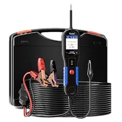
2.3 Parts List
QtyPart Description
1
1 User’s Manual
1
2 Cigarette lighter adapter
1
3 Battery hookup clips
1
4 Probe tip
1
5 Extension cable(20ft.)
1
6 Rugged blow molded case
1
7 Power assist cable
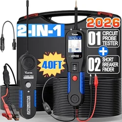
2.4 General Description
The tool is the best electrical tester for reducing diagnostic time in all 6 to 30-volt
vehicle electrical systems. After a simple hook-up of the tool to the vehicle's battery,
you can:
◆ Determine at a glance if a circuit is positive, negative, or open without having to
reconnect clips from one battery pole to another.
◆ Test for continuity with its built-in auxiliary ground lead.
◆ By depressing the power switch, conduct a positive or negative battery current to
the probe tip for testing the function of an electrical component without the use of
jumper wires.
◆ Test for poor ground contacts instantly without performing voltage drop tests. The
tool is also short circuit protected; its internal circuit breaker will trip if it becomes
overloaded.
◆ Follow and locate short circuits without wasting fuses. The tool's long cable allows
you to test along the entire length of the vehicle without constantly searching for
suitable vehicle grounds
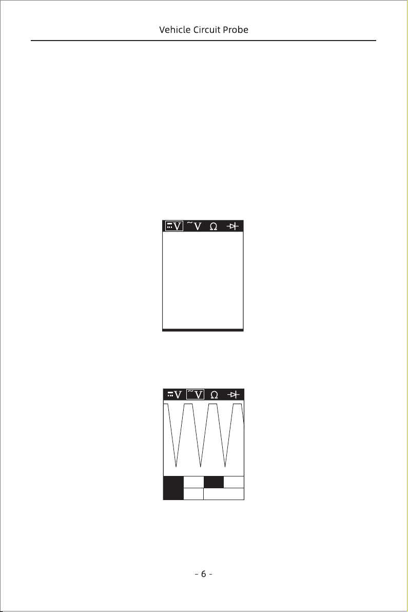
2.5 Power
The tool is powered via the vehicle battery. Connect the RED battery clamp to the
POSITIVE terminal of the vehicle's battery, and the BLACK clamp to the NEGATIVE
terminal. When the tool is first connected to a battery (power source), it will sound a
beep and the Head Lights will be on to illuminate the test area of the probe tip.
2.6 Quick Self-Test
Before you test a circuit or component, be sure your tool is in good order by doing a
quick self-test.
With the tool connected, perform a quick self-test. The power switch is a momentary
rocker switch located on the tool's body. Flanking the switch are positive and
negative
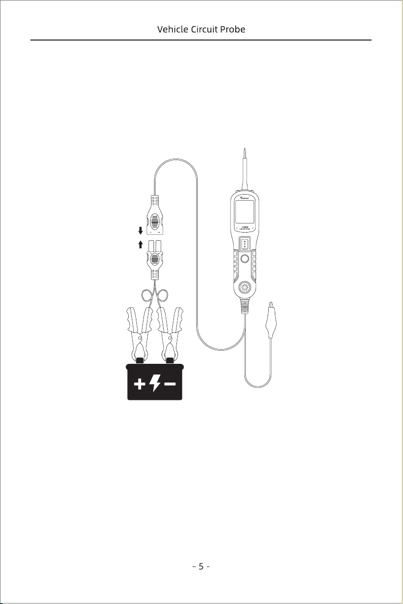
Figure 1
2.7 Auto Circuit Breaker
The tool is short-circuit protected. Its internal circuit breaker will trip if it becomes
overload. The circuit breaker is a valuable test tool as well as a safety measure to
protect the tool from overload.
When circuit breaker tripped, all other functions of the tool are still active, which
means you can still probe a circuit and observe the voltage reading. When the circuit.
IMPORTANT:
power switch in the tool if you first press the switch, then contact the tip to the
component. The arcing will take place at the tip instead of the contacts of the switch.
markings.
Press the Power Switch forward to activate the tip with a positive voltage. The Red
LED should light up and LCD display will read the battery voltage. A beep tone will
sound. Let go of the power switch and the LED will turn off and the tone will cease.
Press the Power Switch backward to activate the tip with a negative voltage. The
green LED should light up and the LCD display will read 0.0V (ground). A beep tone
will sound. Let go of the power switch and the LED will turn off and the tone will
cease. Your tool is working correctly and is now ready for use. (Figure 1)
When powering-up components, you can increase the life of
breaker is tripped, the tool will NOT be able to conduct battery current test to the tip
even when the power switch is pressed. Intentionally tripping the breaker and using
the tool to probe can be considered an added precaution against accidental
pressing of the power switch.
Figure 2
12.1V
Figure 3
Max 17.9 Freq Hz
Min 0.3 50
2.8 Work mode
There are four modes to diagnose the electrical systems, which can be accessed by
depressing the Mode Button and cycling through each one.
DC voltage
While the tool in this mode, contact the probe tip to a circuit, then the LCD display will
read the DC voltage with a resolution of 0.1 volt. (Figure 2)
AC voltage
While the tool in this mode, contact the probe tip to a circuit, then the LCD display
will read the Max. Voltage, the Min. Voltage and frequency.(Figure 3)
Resistance
While the tool in this mode, contact the probe tip to a circuit, then the LCD display will
read the resistance between the tip and auxiliary ground lead. (Figure 4)

Figure 4
1.2K
Figure 5
1.2K
Diode
In this mode, the probe tip contact the positive terminal of the diode, connect the
auxiliary ground lead to the negative terminal of the diode, the screen will display the
forward voltage drop, indicates the forward bias. If switch the probe tip and
auxiliary ground lead, the screen will not display the voltage, indicates the reverse
bias.
3.1 Voltage & Polarity Testing
3. Operating Instructions
While the tool is in DC Voltage mode, contact the probe tip to a POSITIVE circuit. The
red LED will light up and the LCD displays the voltage with a resolution of 0.1V. A beep
tone will sound.
If contact the probe tip to a NEGATIVE circuit, the green LED will light up and the LCD
displays the voltage with a resolution of 0.1V. A beep tone will sound.
If contact the probe tip to an OPEN circuit. Neither of the LED will light up. (Figure 6)
Figure 6
Figure 7
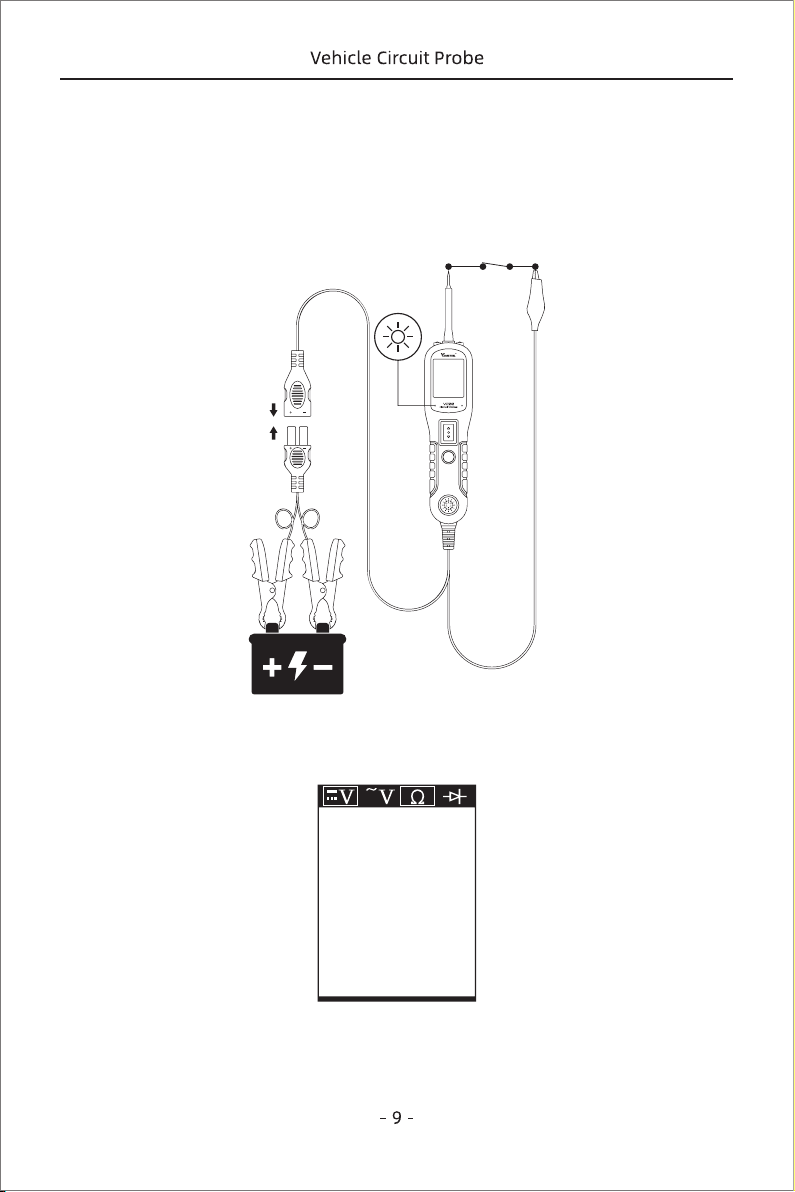
Figure 9
1.2K
Figure 8
3.2 Continuity Testing
While the tool is in Resistance mode, using the probe tip with chass is ground or the
auxiliary ground lead, continuity can be tested on wires and components attached or
disconnected from the vehide's electrical system.
When the probe tip is contacting a good ground, the LCD will indicate “0.0Ω” and
green LED will be on. A beep tone will sound (Figure 8)
In other cases, the LCD only indicates the resistance value, (Figure 9)
If the resistance value is greater than 100KΩ, the LCD will show “0L”.
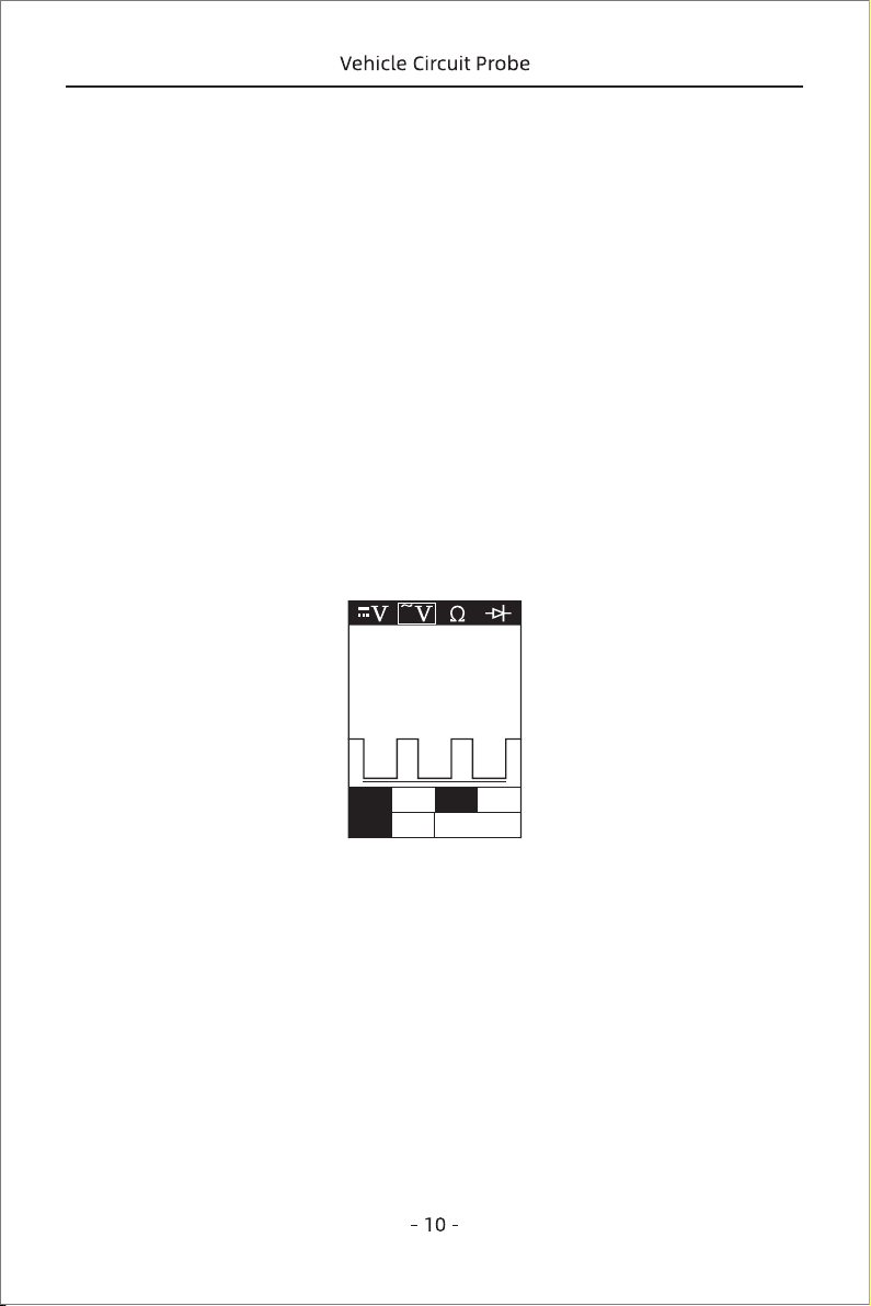
Figure 10
Max 12.4 Freq Hz
Min 0.2 43.0K
There is also another way to prove continuity of connections to ground or battery.
Power up the connection using the power switch. If the circuit breaker trips, you
have a good solid low resistance connection.
Note: You can use the probe tip to pierce the plastic insulation on a wire. This means
that you can test the circuit without disconnecting anything.
3.3 Signal Circuit Testing
Once you extract a DTC from the vehicle and realize that troubleshooting begins with
some kind of sensor circuit, there is a quick test you can perform to verify the code.
Testing your sensor is easy while using the tool.
For example, you suspect there is a problem with your M.A.P. sensor circuit, then
follow the procedure below to test this sensor:
◆ Set the tool in AC Voltage mode, using the probe tip with chassis ground or the
auxiliary ground lead.
◆ Connect vacuum pump to MAP sensor.
◆ Contact the probe tip to the MAP sensor positive terminal and observe the LCD
readings which should be a sine wave in normal condition.
◆ Apply vacuum.
◆ Release vacuum and observe the LCD readings. (Figure 10)
3.4 Activating Components in Your Hand
While the tool is in DC voltage mode, by using the probe tip in connection with the
auxiliary ground lead, components can be activated right in your hand, thereby
testing their functions.
Connect the auxiliary ground lead to the negative terminal or ground side of the
component being tested. Then contact the probe tip to the positive terminal of the
component, the green LED should light up, indicating continuity through the
component. While keeping an eye on the green LED,quickly press and release the
power switchforward. If the green LED went out and the red LED came on, you may
proceed with further activation. Push the power switch forward and hold it down to
If the LCD readings are abnormal, there is a problem with this sensor.
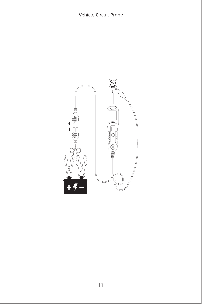
Figure 11
provide power to your component. With the power switch pushed forward, power
will flow from the positive lead on the battery to the probe tip, then to the compo-
nent’s positive terminal, through the component, through the auxiliary ground lead,
then back to the tool, and all the way back to the vehicle’s battery’s ground.
(Figure 11)
(1) Press the power switch forward to activate the bulb.
(2) Contact the tip to the positive terminal of the bulb.
(3) Connect the negative auxiliary clip.
3.5 Activating Components in The Vehicle
While the tool in DC Voltage mode, contact the probe tip to the positive terminal of the
component, the green LED should light up, indicating continuity to ground. While
observing the green LED. Quickly press the power switch button forward and release,
if the green LED went out and the read LED comes on, you may proceed with further
If the green LED went off at that instant or if the circuit breaker tripped, the tool has
been overloaded. This could happen for the following reasons:
◆ The contact you are probing is direct ground or negative voltage.
◆ The component you are testing is short-circuited.
◆ The component is a very high current component (i.e., starter motor).
If the circuit breaker is tripped, reset it by waiting for it to cool down (15 sec.)
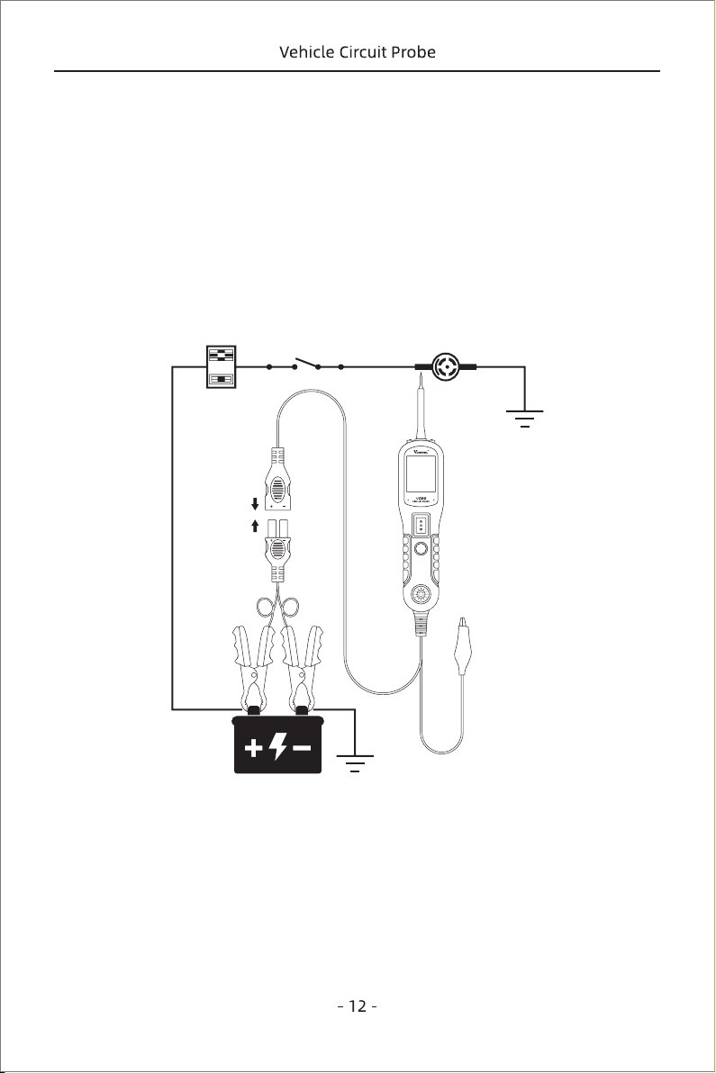
Figure 12
activation. (Figure 12) If the green LED went off at that instant or if the circuit breaker
tripped, the tool has been overloaded. This could happen for the following reasons:
(1) The contact you are probing is a direct ground
(2) The component you are testing is short-circuited
(3) The component is a very high current component (i.e., starter motor).
If the circuit breaker is tripped, reset it by waiting for it to cool down (15 sec.)
WARNING: Haphazardly applying voltage to certain circuits can cause damage to a
vehicle's electronic components. Therefore, it is strongly advised to use the vehicle
manufacturer's diagram and diagnosing procedure while testing.
NOTE: When powering up components, you can increase the life of power switch if
you first press the switch, then contact the tip to the component. The arcing will take
place at the tip instead of the contacts of the switch.
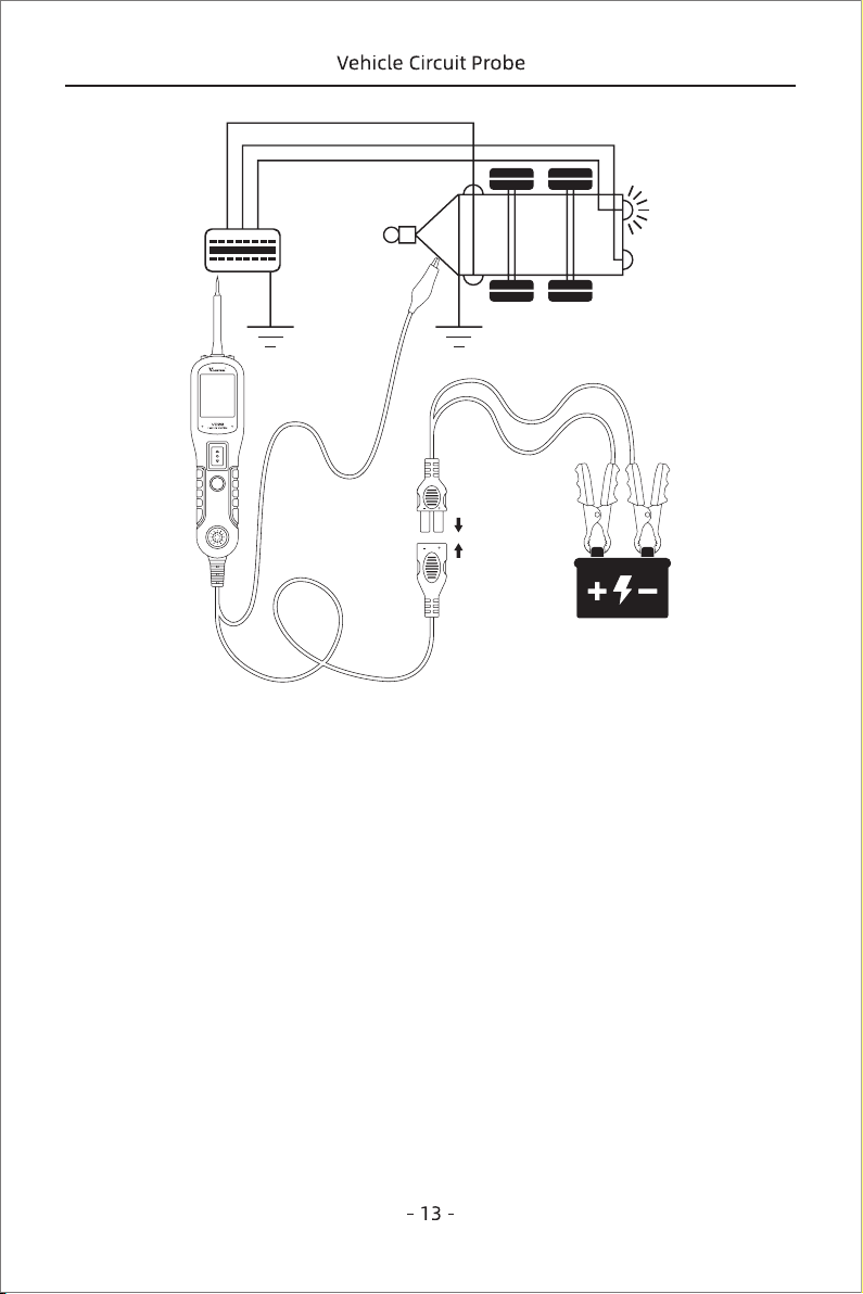
3.6 Testing Trailer Lights and Connections
When the tool in DC Voltage mode, clip the auxiliary ground lead to the trailer
ground, probe the contacts at the jack and then apply voltage to the probe tip. This
lallows you check the function and orientation of the connector and trailer lights.
(Figure 13)
If the circuit breaker tripped, that contact is likely a ground. Reset the ciccuit breaker
by letting it cool down for 15 seconds.
3.7 Activating Components W/Ground
While the tool in DC Voltage mode, contact the probe tip to the negative terminal of
the component, the red LED should light up. While observing the red LED, quickly
press the power switch backward and release the button If the red LED went out and
the green LED came on, you may proceed with further activation. (Figure 14) If the
green LED went off at that instant or if the circuit breaker tripped, the tool has been
overloaded. This could happen for the following reasons:
(1) The contact you are probing is a direct positive voltage.
(2) The component you are testing is short-circuited.
(3) The component is a very high current component(i.e., starter motor).
If the circuit breaker is tripped, reset it by waiting for it to cool down (15 sec.)
Figure 13
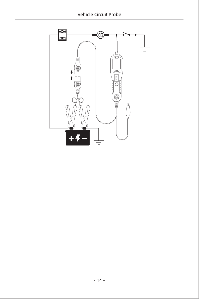
Figure 14
WARNING: With this function, if you are contacting a protected circuit, a vehicle’s
fuse can be blown or tripped if you apply ground to it.
3.8 Red/Green Polarity LED
The Red/Green Polarity LED lights up when the probe tip voltage matches the battery
within ±0.4 volts. It is added information that could be valuable to the
technician.
If the circuit you are testing is not within a 0.4 volt (plus or minus) of supply voltage,
you will see the voltage reading on the LCD but you will not hear a tone or see a red
or green LED. This tells you either you have a voltage drop in excess of 0.8 volt from
battery voltage or you are probing a circuit that has an increase of a 0.8 volt
or more over battery voltage. To determine battery voltage, simply remove the
tip from the circuit and press the power switch forward. Battery voltage will then be
displayed on the LCD.The difference between the battery voltage and what is read
on the circuit is either voltage drop or voltage increase.This allows you to determine
a voltage drop without running back to check the battery. It’s just another one of time
saving feature the tool has.
3.9 Following & Locating Short Circuits
In most cases a short circuit wil appear by a fuse or a fusible link blowing or an

electrical protection device tripping (i.e., a circuit breaker). This is the best place to
begin the search.
Remove the blow fuse from the fuse box.
Use the probe tip to activate and energize each of the fuse contacts.The contact
which trips the circuit breaker is the shorted circuit. Take note of this wire's
identification code or color.
Follow the wire as far as you can along the wiring harness.
Here is an example for this application.
If you are following a short in the brake light circuit, you may know that the wire must
pass through the wiring harness at the door sill. Locate the color-coded wire in the
harness and expose it.
Probe through the insulation with the probe tip, and depress the power switch
forward to activate and energize the wire.
If the circuit breaker tripped, you have verified the shorted wire. Cut the wire and
energize each end with the probe tip. The wire end which trips the circuit breaker
again is the shorted circuit and it will lead you to the shorted area.
Follow the wire in the shorted direction and repeat this process until the short is
located.
3.10 Checking for Bad Ground Contacts
Probe the suspected ground wire or contact with the probe tip.
Observe the green LED. Depress the power switch forward then release. If the green
LED went out and the red LED came on, a beep will sound, this is not a true ground.
If the circuit breaker tripped, this circuit is more than likely a good ground: Keep in
mind that high current components such as starter motors will also trip the circuit
breaker.
5.Test Tool Knowledge
Is the tool computer and air bag safe?
The tool LED and LCD pull no more than 1 millamp of current, therefore when using it
as a test light or multimeter it is computer and airbag safe. However, pressing the
power switch is a different story. When you press the switch forward, you are
4. Test Tool Specifications
◆ DC voltage range: 0-65V + 1 digit
◆ Resistance range: 0-100 kΩ
◆ Frequency response of tone pass through OHz to 10Khz
◆ Circuit Breaker
◆ Rating current: 1-10 Amp
◆ Testing Standard:
100% current: Hold > 1 hour
150% current: trip in one hour
200% current: trip in 3-30 seconds.
300% current: trip in 0.5-4.0 seconds.

conducting full battery current to the tip of the probe. There is a nice safety feature
built into the tool. Simply connect the extra ground lead to the tool and press the
power switch forward until it trips the circuit breaker. This will prevent power from
going to the tip but still allow you to use the tool as a multimeter. When you are away
from computer components, simple press the reset button and you are ready to
power up again.

6. Warranty and Service
6.1 Limited One Year Warranty
6.2 Service Procedures
This warranty is expressly limited to buyer who purchase VDIAGTOOL V200 product
for purposes of resale or use in the ordinary course of the buyer’s bussiness.
VDIAGTOOL V200 is warranted against defects in materials and workmanship for
one year (12 months) from date of delivery to the buyer. This warranty does not cover
any part that has been abused, altered, used for a purpose other than for which it
was Intended,or used in a manner inconsistent with instructions regarding use.
The exclusive remedy for any tool found to be defective is repair or replacment,and
it shall not be liable for any consequential or incidental damages
Trademaks
VDIAGTOOL is the trademark of SHENZHEN CHUANG XIN HONG TECHNOLOGY
CO., LTD
All other marks are trademarks or registered trademarks of the respective holder.
Copyright Information
©2017 SHENZHEN CHUANG XIN HONG TECHNOLOGY.,LTD
All reghts reserved
Disclaimer
The information, specifications and illustrations in this user manual are based on the
latest information available at the time of printing.
VDIAGTOOL reserves the right to make changes at any time without notice.
Visit our official website via
www.vdiagtool.com
For techniaal support
Please contact your dealer directly to get fast response or send us e-mail at
For wholesale business, send us e-mail at