USER MANUAL
V500
WWW.VDIAGTOOL.COM

Safety Information
To ensure your safety and prevent damage to the device or vehicle, please carefully read and follow all instructions in this
manual before use.
When operating the device, always verify proper testing procedures and strictly adhere to the instructions provided. As
automotive electrical systems may vary, you must assess potential risks and ensure a safe testing environment.
Always observe all safety warnings, use appropriate tools, and disconnect power sources when necessary. Improper opera-
tion may result in personal injury, equipment damage, or voided warranty.
Safety Messages
Safety messages use standardized signal words to indicate hazard levels and prevent injuries or equipment damage:
DANGER WARNING
Will result in death or serious injury if ignored Could result in death or serious injury if ignored
Indicates an immediately life-threatening hazard. Indicates a potentially dangerous situation.
Safety Instructions
This manual covers known safety hazards, but cannot anticipate all possible risks. You are responsible for ensuring safe
operating conditions and procedures.
DANGER
• Always ventilate the service area when engine is running or use building exhaust removal system if available
• Carbon monoxide is odorless and deadly - can cause loss of consciousness or death
WARNINGS
• Always keep a fire extinguisher suitable for gasoline, chemical, and electrical fires nearby.
• Never operate or observe the tool while driving—distraction can lead to fatal accidents.

• Keep clothing, hair, hands, tools, and test equipment away from moving or hot engine parts.
• Perform automotive testing only in a safe, controlled environment.
• Ensure proper ventilation—exhaust gases are poisonous.
• Never connect or disconnect test equipment while the ignition is ON or the engine is running.
• Place wheel chocks in front of drive wheels and never leave the vehicle unattended during testing.
• Wear ANSI-approved safety eye protection at all times.
• Exercise extreme caution around ignition coils, distributor caps, spark plugs, and wires—high voltage is present when the
engine is running.
• Before testing, ensure the transmission is in P (A/T) or Neutral (M/T) and the parking brake is engaged.
• Keep the scan tool clean and dry; avoid contact with oil, water, or grease. Clean only with a mild detergent and soft cloth.
• Do not modify, disassemble, or expose the tool to extreme temperatures or moisture.
• This tool is not a substitute for professional diagnostic equipment—use with caution.
• The manufacturer is not liable for damages caused by misuse, negligence, or unauthorized modifications.
Legal Information
Trademarks
VDIAGTOOL is a registered trademark of Shenzhen VDIAGTOOL Technology Co., Ltd in the United States and other jurisdic-
tions. All other product names mentioned herein may be trademarks of their respective owners.
Copyright Information
© 2017 Shenzhen VDIAGTOOL Technology Co., Ltd. All rights reserved.
No reproduction, distribution, or transmission of this manual is permitted without express written authorization from
VDIAGTOOL. This prohibition applies to all forms of copying including electronic, mechanical, photocopying, and recording.
Disclaimer & Liability Statement
Product Documentation Notice
All illustrations, specifications, and technical data in this manual are for reference only and subject to change without notice.

For the latest documentation, visit: https://www.vdiagtool.com/support/downloads
Limitation of Liability
VDIAGTOOL expressly disclaims all liability for:
• Any direct, indirect, incidental, or consequential damages
• Loss of profits or business interruption
• Product modifications or unauthorized use
This manual does not:
• Modify existing purchase/lease agreements
• Create additional liabilities for VDIAGTOOL
• Constitute additional product warranties
IMPORTANT:
Always consult this manual before operation, with special attention to all safety warnings. VDIAGTOOL reserves the right to
modify product specifications at any time.
Product Support & Training Resources
Technical Support
• Official Website: www.vdiagtool.com
• Support Email: [email protected]
• US Hotline: +1-213-355-7171
• Online Form: https://www.vdiagtool.com/support/tech-support
Training Videos
Free product operation videos:
1. Visit Training Center: https://www.vdiagtool.com/support/training-center
2. Select Circuit Testers category, then watch model-specific tutorials

Contents
1. Product Introduction................................................................................................................................................. 1
1.1 Product Overview........................................................................................................................................................................................ 1
1.2 Technical Specifications............................................................................................................................................................................ 3
1.3 Keypad Introduction.................................................................................................................................................................................. 4
2. Product Features........................................................................................................................................................ 5
2.1 Smart Test....................................................................................................................................................................................................... 5
2.1.1 Voltage Test........................................................................................................................................................................................ 5
2.1.2 Resistance Test.................................................................................................................................................................................. 6
2.1.3 Positive/Negative Test.................................................................................................................................................................... 6
2.2 Resistance....................................................................................................................................................................................................... 6
2.3 Multimeter..................................................................................................................................................................................................... 6
2.4 Oscilloscope.................................................................................................................................................................................................. 8
2.5 0-5V Power Supply..................................................................................................................................................................................... 9
2.6 Component Test........................................................................................................................................................................................... 9
2.7 Relay............................................................................................................................................................................................................... 11
2.8 Injector.......................................................................................................................................................................................................... 12
3. Setting....................................................................................................................................................................... 14
3.1 Language..................................................................................................................................................................................................... 14
3.2 Floodlight..................................................................................................................................................................................................... 14
3.3 Voice.............................................................................................................................................................................................................. 14
3.4 Self Test......................................................................................................................................................................................................... 14
3.4.1 LCD Test............................................................................................................................................................................................. 14
3.4.2 Key Test.............................................................................................................................................................................................. 14
3.4.3 Led Test.............................................................................................................................................................................................. 15
3.5 Display Mode............................................................................................................................................................................................. 15
3.6 Update.......................................................................................................................................................................................................... 15
3.7 About............................................................................................................................................................................................................. 17

4. Test Applications...................................................................................................................................................... 17
4.1 Continuity Test........................................................................................................................................................................................... 17
4.2 Signal Circuit Test (Oscilloscope Test)............................................................................................................................................... 19
4.3 Activating Components in Your Hand.............................................................................................................................................. 20
4.4 Activating Components in Vehicle..................................................................................................................................................... 21
4.5 Activating Components w/Ground.................................................................................................................................................... 23
4.6 Checking for Bad Ground Contacts................................................................................................................................................... 24
4.7 Following & Locating Short Circuits.................................................................................................................................................. 25
4.8 Trailer Lights and Connection Test..................................................................................................................................................... 25
5. Warranty................................................................................................................................................................... 26
6. Contact Us................................................................................................................................................................. 26
1. Product Introduction
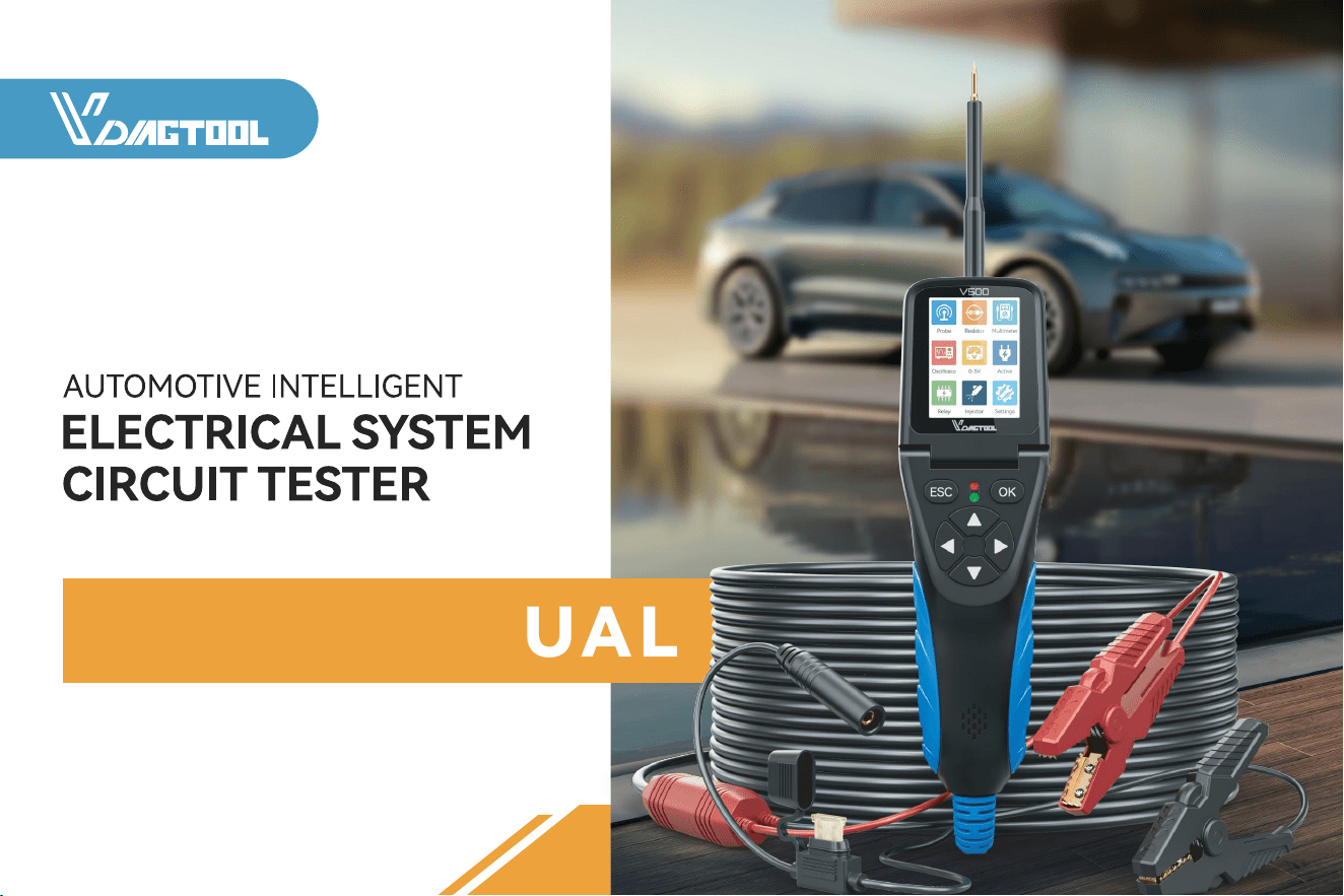
VDIAGTOOL V500 Automotive Intelligent Electrical System Circuit Tester is the newest generation intelligent tool with 2.36
inch large size LCD screen display. It is dedicated to test all 9V-30V vehicle electrical systems.
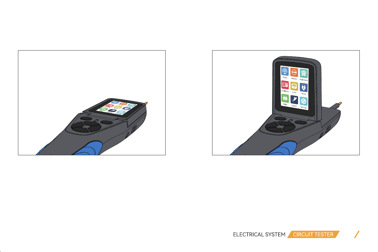
The screen can be folded up to 90°, which allows you to see real-time data at different screen angles during testing.
01
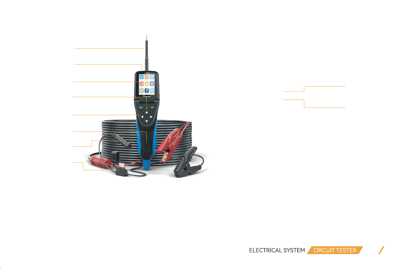
1.1 Product Overview
1. Probe Tip: Contact the circuit or component for testing 6. Auxiliary Ground Lead: Auxiliary clip of ground lead
2. Front LED Light: Used for lighting in dark working areas 7. USB Port: Update via USB connection to PC
3. LCD Screen: Display test results 8. Relay Test Port: Connect the relay test cable
4. Red/Green LED Indicator: Positive and Negative indicator light 9. Speaker: Buzzer for warning or remind
5. Key Button Operation: 7-Key Navigating for fast operation 10. Fuse: Protect the device from damage due to overload
02
①
②
③
④
⑤
⑥
⑦
⑩
⑧
⑨
1.2 Technical Specifications
Product Parameters:
Product Dimensions:
• Main line: OD 7.8mm, Length 6m • Clip line: OD 4.5mm, Length 0.4m
• Extension line: OD 4.5mm, Length 1m • Relay line: OD 4.0mm, Length 0.5m
• USB line: OD 3.5mm, Length 0.5m
Accessories Included:
• V500 Tool × 1 • Fuse × 3
• Probe Tip × 1 • Relay Test Cable × 1
• Fine Probe Tip × 1 • Alligator Battery Clip × 1
• Probe Tip Extension Cable × 1 • Type-C Data Cable × 1
• Wire Piercing Probe × 2 • User Manual × 1
• Banana to Banana Plug Test Lead × 2
03
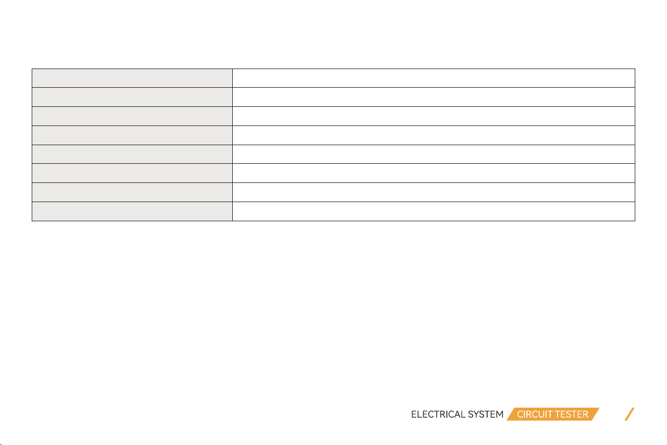
Display LCD Display
Operating Voltage 9V - 30V DC
Voltage Measurement Range
0.1V - 100V
Resistance Measurement Range 0KR - 200KR
Operating Temperature 0°C - 50°C (-32°F - 122°F)
Storage Temperature
-20°C - 70°C (-4°F - 158°F)
Working Environment Temperature
0°C - 50°C (-32°F - 122°F)
Power Source
By Connecting to Car Battery

Accessories Description:
• Probe Tip: Contact the circuit or component for testing
• Fine Probe Tip: Used to contact plugs or pins in the car's circuits
• Probe Tip Extension Cable: Extends the reach of the probe for testing in distant or confined spaces
• Wire Piercing Probe: Piercing wire insulation for electrical measurements without damaging the wire, providing a clearer
understanding of the car's circuits
• Banana to Banana Plug Test Lead: An adapter and extension cable used to connect devices with banana plug connectors
• Relay Test Cable: Used to test the functionality of relays
• Alligator Battery Clip: Secures connections to battery terminals for testing
1.3 Keypad Introduction
ESC button: Returns to the previous screen. For other tests, press ESC button once to exit.
OK button: Confirm key
Up button: Navigation key or voltage output, numerical adjustment
Left button: Navigation key
Right button: Navigation key
Down button: Navigation key or voltage output, numerical adjustment
04
OK

2. Product Features
VDIAGTOOL V500 features the following functions: Smart Test, Multimeter, Oscilloscope, 0-5V Power Supply, Component
Test, Relay, Injector and other additional functions.
2.1 Smart Test
This feature contains Voltage Test , Resistance Test, Positive/Negative Test. It is mainly used for quick test without switching
between different test modes. It can automatically recognize the measured signal and display values of voltage or OHMs.
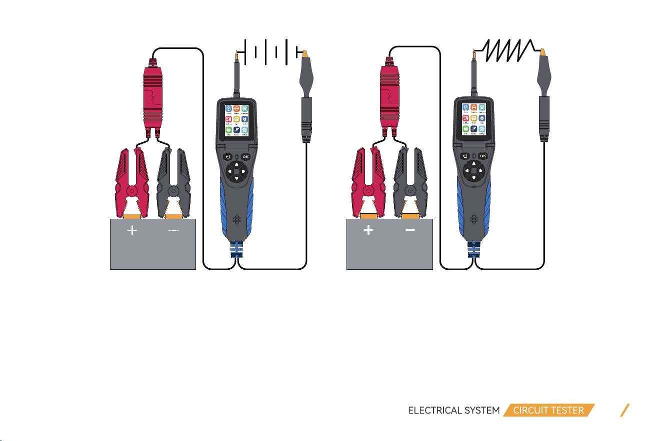
2.1.1 Voltage Test
When the probe clip (auxiliary ground lead) is connected to the ground wire, the probe will automatically enter into the
voltage display mode when a voltage signal detected on the Probe Tip, it will display the test voltage.
As shown in the picture below, “VCC” means that the battery supply voltage is 12.14V, and “VDC” is the current test DC
voltage value 12.11V.
05
Probe
12.11
VDC
VCC V
V
12.14

06
2.1.2 Resistance Test
When the probe clip (auxiliary ground lead) is connected to an electrical circuit of resistance and the Probe Tip is connected
to the other end of the resistance, the probe will automatically enter into the resistance display mode and display the resis-
tance values.
2.1.3 Positive/Negative Test
When the probe detected voltage deviation of ±0.8v from the power supply, the RED LED lights ON, meanwhile it displays
the voltage values, and the speaker sounds regularly. When Probe detected the negative signal of the power supply, the
GREEN LED lights ON, and the speaker sounds regularly.
2.2 Resistance
This feature is mainly used to measure the resistance value of electronic components.
Please refer to 2.1.2 for more details.
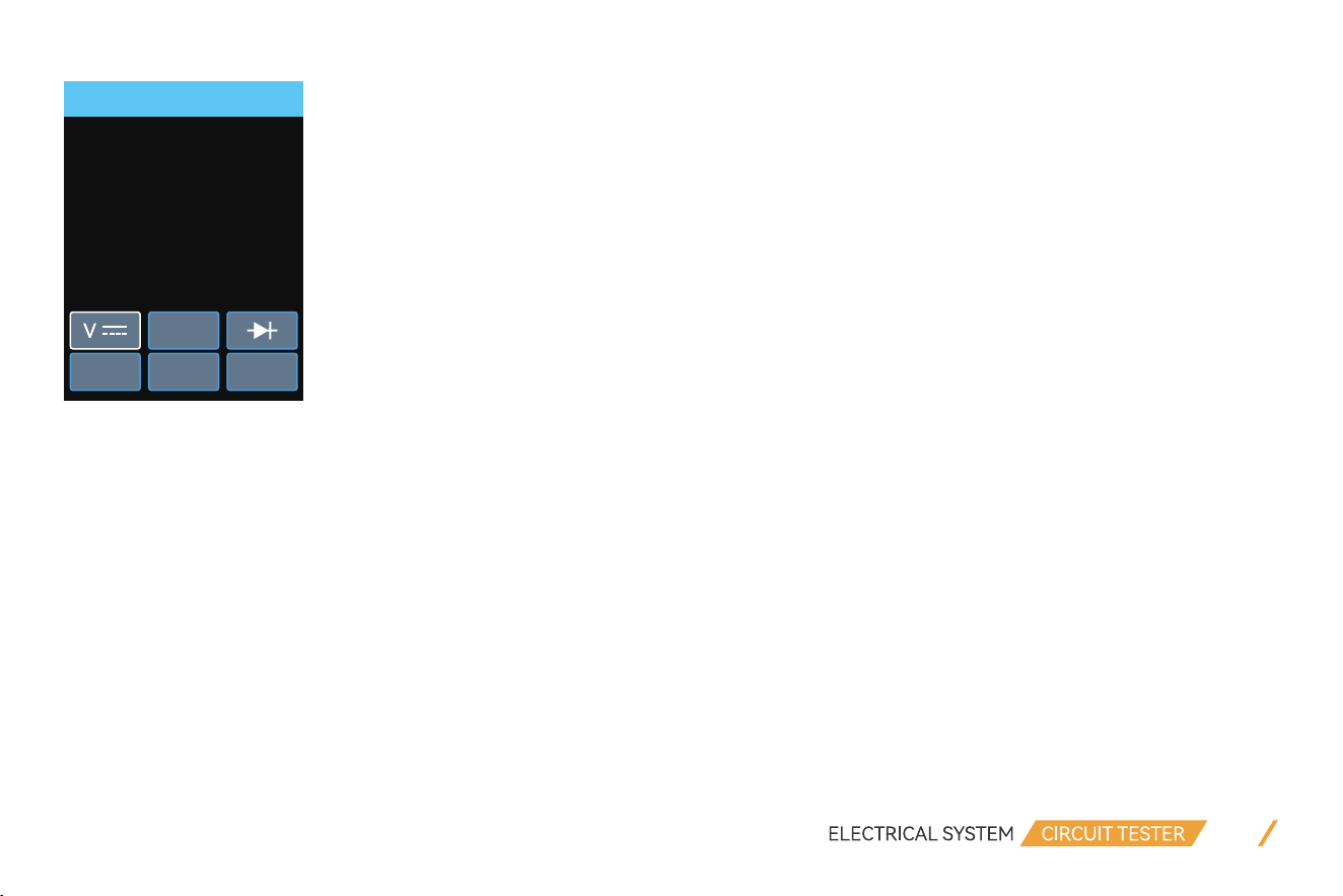
2.3 Multimeter
It is also known as a volt-ohm-milliammeter, volt-ohmmeter or VOM.
This feature is a measuring instrument that can measure multiple electrical properties.
07
Voltage
12.2
Max:12.22
Min:0.00
V
Ω
A Hz P-N
The bottom of the interface is the functional area, from left to right are: Voltage, Resistance, Diode, Current, Frequency and
Polarity.
You can press the “Left” or “Right” button to select the test mode.
(1) Voltage (VDC): Connect the probe clip (auxiliary ground lead) to the negative pole, and connect the probe tip to the mea-
sured voltage.
(2) Resistance (OHM): Connect the probe clip (auxiliary ground lead) to one side of the Resistance being measured, and the
probe tip to the other side.
(3) Diode (DIO): Connect the probe clip (auxiliary ground lead) to one side of the Diode being measured, and the probe tip
to the other side. Meanwhile it will display the voltage and show Positive and Negative of Diode.
(4) Current (AMP): The probe is connected in series in the circuit under test, it will display the current value.
(5) Frequency (HZ): Display the frequency of the measured signal and duty cycle value.
(6) Polarity: Display whether the current measured line is positive or negative.

08
10.0
V
8.0
6.0
4.0
2.0
0.0
Status: Run
DIV : 2.0 V Time : 1 ms
Max : 0.1 V Freq :
Min : 0.0 V Duty : 0 %
NOTE:
When testing the current, make sure the wires are in series connection, not in parallel connection. If they are in parallel
connection, it will cause the device to trigger the overload protection and then restart. If you have any questions while using
the product, feel free to contact us at [email protected].
2.4 Oscilloscope
This feature is an electronic test instrument that displays electrical signals graphically, usually as a Voltage (vertical or Y axis)
versus Time (transverse or X axis).
This function can be displayed in vertical or transverse screen.
The Voltage on the Y axis shows 0.0V to 10.0V and the Time on the X axis shows 1ms to 500ms.
NOTE:
Press “OK” button to pause or run waveform refresh.

09
VOLTS SUPPLY
Output Voltage
V
5.0
Set Value
V
5.0
+-0.1V
-+1.0V
2.5 0-5V Power Supply
This feature is a type of power supply that provides a regulated and stable 0-5V DC (direct current) output voltage. This
low-volt- age power supply is commonly used to power electronic devices that require a 0-5V DC supply, including
micro-controllers, sensors, LED lights, USB charging devices, and other low-power electronic components.
NOTE:
0-5V Power Supply is designed as an active mode, but this functions is different from the Component Activation. It can
adjust the voltage output under 5V and limit the current to 100mA. (This is safety to avoid burning out electric components.)
2.6 Component Test
This feature is to verify the input/output behavior of the test object. It ensures that the test object's functionality works
correctly and completely as per the desired specification. This type of testing focuses on performing separate tests on each
component.
While testing, it will show as below:

10
MOMENT
[DOWN and green on’ -’]
[ UP and red on’ +’]
VDC V0.0
AMP A0.0
VCC V12.2
MOMENT
H
I
LATCH
H
I
SETTING
A
PULSE
H
I
VDC: Detected Voltage
AMP: Detected Current
VCC: Power Supply Voltage
It has three activation mode:
(1) “MOMENT” Mode: Press “Left” or “Right” button to select the activation mode. Press and hold the “UP” or “Down” button
to perform the power supply, and release “UP” or “Down” button to stop.
(2) “LATCH” Mode: Press the “UP” or “Down” button to perform the power supply, and press “UP” or “Down” button again
to stop.
(3) “PULSE” Mode: Press and hold the “UP” or “Down” button to perform the power supply, and release “UP” or “Down”
button to stop.
(4) “SETTING” Circuit Breaker: Press “UP” or “Down” button to adjust the overload current values from 1A - 18A.
11
RELAY TEST
86
85
30
87
86
85
87A
30
87
VCC (V)
12.2
Relay not on
[ UP ] start test
[ OK ] Help
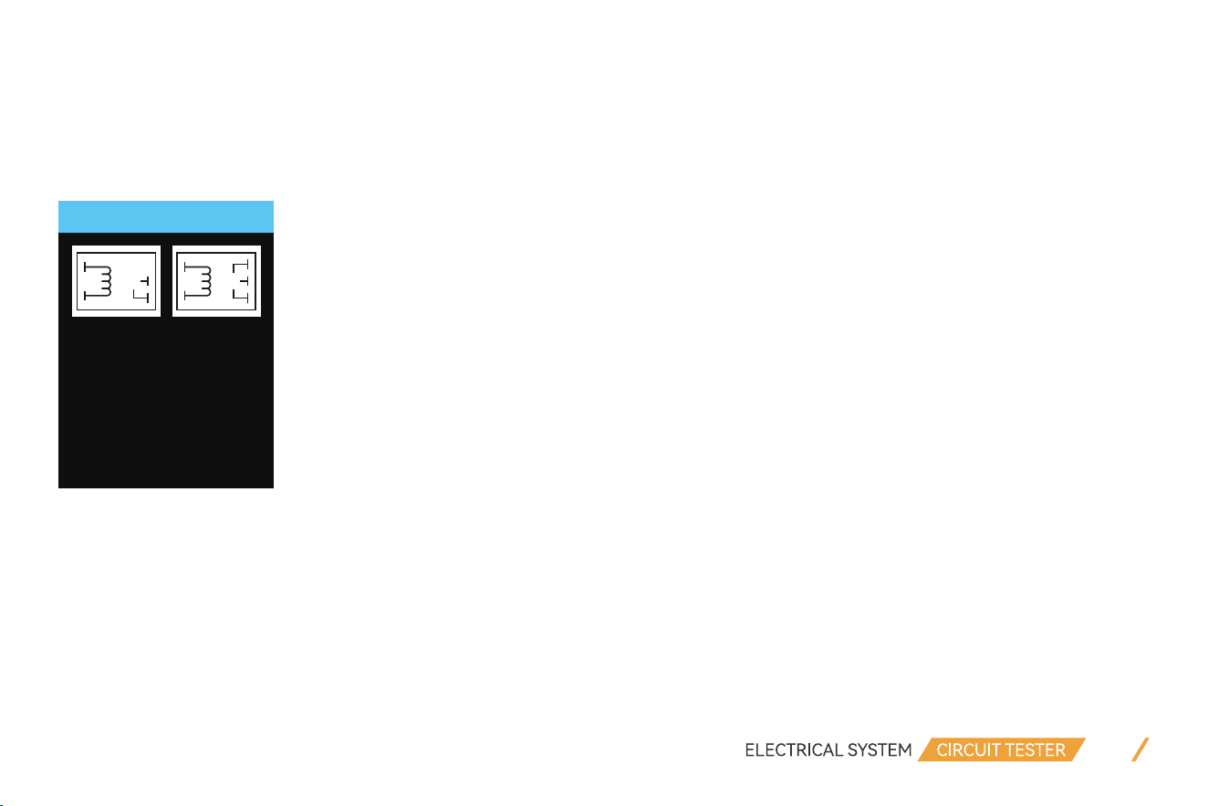
2.7 Relay
This feature includes the review of protective devices in a system. Protective devices and periodic reviews are very important
above all for the safe operation of power supply networks. The protective relay test refers to the protective relay. The proper
operation of a protective relay has to be monitored over its entire life or period of operation. When you select this function
and the Relay is not connected, the interface will show as below:
The “VCC” at the center of this interface displays the power supply voltage value . It shows 2 types of common automotive
relay diagrams (4-terminal relay and 5-terminal relay). Press “UP” button to start test and press “OK” button to view the
wiring connection diagram of these 2 different relays.
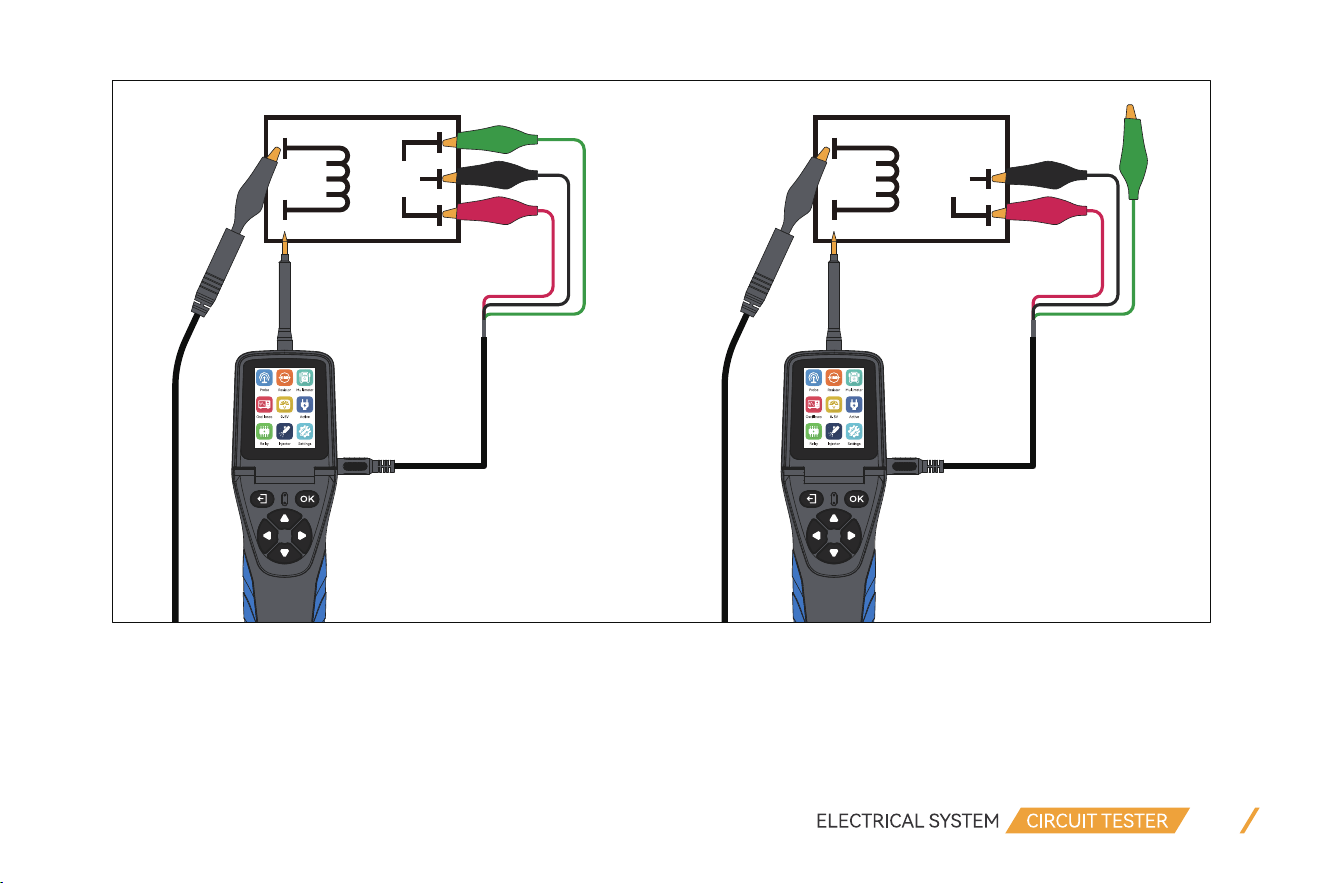
The below pictures are Relay wiring connection examples:
12
86
85
87A
30
87
86
85
30
87
2.8 Injector
This feature uses probe tip to output different pulse signals to the injector and check the injector spraying status. This
feature can help diagnose injector conditions.

13
Injector
[ OK :250 ms of ’ +’]
M1 M2
M4M3
There are 4 Signal Output Mode:
(1) Select Mode 1 and press “OK” button, it will output 1 pulse with a positive pulse width of 250ms.
(2) Select Mode 2 and press “OK” button, it will output 7ms positive, then 20ms negative, cycle 1.4s.
(3) Select Mode 3 and press “OK” button, it will output 4ms positive, then 10ms negative, cycle 1.4s.
(4) Select Mode 4 and press “OK” button, it will continuously output positive for 7ms, then negative for 20ms. Press “ESC”
button to stop.
Here are the procedures of how to perform Injector Test:
(1) Turn off the Vehicle’s engine.
(2) Connect the BLACK clip to the negative terminal of the battery and the RED clip to the positive terminal.
(3) Unplug the connector from the fuel injector, connect the probe auxiliary ground lead to the negative side of the injector,
and probe tip to the positive side.
(4) After entering into the Injector Test function, select the test mode.
(5) Press “OK” button to trigger the test.
(6) Check the injector spraying status to diagnose the condition.

14
3. Setting
3.1 Language
There are nine languages to choose from, they are English, Simplified Chinese, French, Spanish, German, Russian, Italian,
Portuguese, Polish.
3.2 Floodlight
Here you can turn the headlight of your device on or off.
3.3 Voice
Here you can turn the sound of the device on or off.
3.4 Self Test
3.4.1 LCD Test
When entering this test, the screen will display different colors to check whether the screen can display normally and wheth-
er there are black spots.
NOTE:
Pressing the ESC key will exit the test directly. It means the ESC key is working properly.
3.4.2 Key Test
When entering this test, the screen will display the buttons as shown below. Press the corresponding button and the corre-
sponding symbol on the screen will flash once.

15
ESC OK
Key test
Press [ESC] twice to exit
3.4.3 Led Test
When entering this test, the Floodlight on the head of the device and the positive and negative LED lights at the button
position will remain on, indicating that there is no problem with the device lights.
3.5 Display Mode
Here you can choose whether the device is in Light mode or Dark mode.
3.6 Update
When entering this menu, the screen will display as shown below.
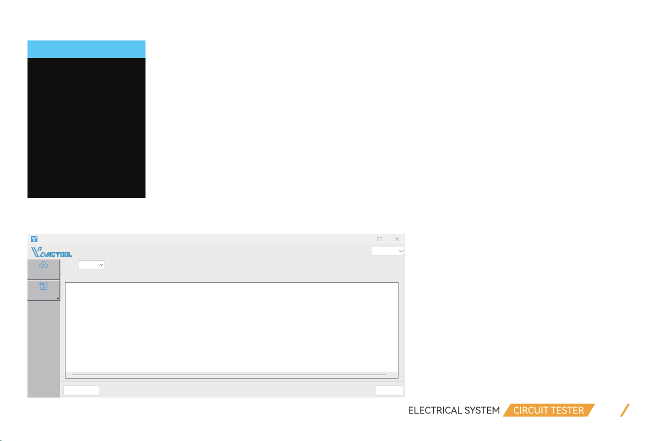
Hold down the key of Down and power on the device, then the device displays “USB mode”, and you can use the computer
software to upgrade the device.
16
Update
Hold down the key of
[Down] and power on
the device, then
the device displays
[usb mode], and you
can use the computer
software to upgrade
the device
VDLINK_25.10
Manual
Upgrade
EnglishLanguage:
Po:
Clear message Upgrade
Prompt messages:
1. The device must enter the upgrade mode
2. To enter the upgrade mode:
3. Press and hold down the arrow key of the diagnostic device (the device does not need to be connected to the OBD po and USB po).
4. Hold down the Down arrow key and use the USB cable to connect the diagnostic device to the computer
5. Wait until UPDATE MODE is displayed on the device screen, and release the arrow key Down. The device enters the upgrade mode successfully
6. Click the upgrade button in the lower right corner

3.7 About
When entering this menu, the screen will display interface as shown below.
4. Test Applications
4.1 Continuity Test
A continuity test is a quick check to see if a circuit is open or closed. Only a closed, complete circuit has continuity. During
a continuity test, a digital multimeter sends a small current through the circuit to measure resistance in the circuit.
When the device is in the “Multimeter”, select the resistance test function, use the probe tip with chassis ground of the
vehicle or auxiliary ground lead, continuity can be tested on wires and components attached or disconnected from the
vehicles electrical system.
When the Probe is contacting a good ground, the LCD screen will display “0.0Ω” and the green LED indicator will also light
up. If the sound enabled from setting, the buzzer will beep at the same time.
17
www.vdiagtool.com
About
Brand: VDIAGTOOL
Model: V500
Software Version: V24.0
Hardware Version: V1.0
Email:
• In other cases, the LCD screen will only display the resistance value.
• If the resistance is greater than 200 KΩ, the LCD screen will display “0L”. There is another way to verify the continuity of
the connection to the ground or battery: while in Component Activation mode, you can supply power to the electrical
system, if the circuit breaker trips, it means that this connections is a good connection with low resistance.
NOTE:
Do not perform any tests on any ECU module, SRS(airbag) system before the system is completely disabled or unplugged;
You can use the probe tip to pierce the plastic insulation on a wire to run test.
18

4.2 Signal Circuit Test (Oscilloscope Test)
Once you extract a DTC from the vehicle and realize that troubleshooting begins with some kind of sensor circuit, there is a
quick test you can perform to verify the code. Testing your sensor is easy while using this tool.
For example, you suspect there is a problem with your M.A.P. sensor circuit, then follow the procedure below to test this
sensor:
(1) Enter into Oscilloscope mode, use the probe tip with chassis ground or auxiliary ground lead.
(2) Connect vacuum pump to M.A.P. sensor.
(3) Touch the probe tip to the positive terminal of the M.A.P. sensor and observe the LCD screen. Generally it should be a
Sine Waveform in good condition.
(4) Apply vacuum pump. Release vacuum pump and observe the reading on the LCD screen.
19
10.0
V
8.0
6.0
4.0
2.0
0.0
Status: Run
DIV : 2.0 V Time : 1 ms
Max : 0.1 V Freq :
Min : 0.0 V Duty : 0 %
If the waveform reading is abnormal, there is a problem with this sensor.
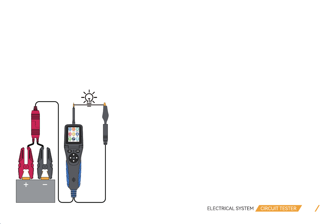
4.3 Activating Components in Your Hand
While the circuit probe is in DC voltage mode, by using the probe tip in connection with the auxiliary ground lead, compo-
nents can be activated right in your hand, thereby testing their functions.
For example: test a bulb’s working condition.
(1) Hook up the battery clip to power supply.
(2) Enter into Active, select MOMENT mode function.
(3) Connect the auxiliary ground lead to the negative terminal of the component being tested, connect the probe tip to the
positive terminal of the component, press “up” button to trigger activation test.
(4) The LCD screen will display the value of VDC, AMP, and VCC.
20

If the probe circuit breaker tripped, it means the probe is overloaded. This could happen for the following reasons:
• The contact you are probing is direct ground or negative voltage.
• The component you are testing is short-circuited.
• The component is a very high current component (i.e., starter motor).
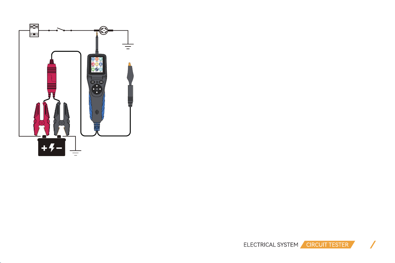
4.4 Activating Components in Vehicle
Importance:
• The activation mode is only designed for supply powers or ground, and cannot be used for any sensitive electronics equip-
ment (such as ECU, sensor module), otherwise there is a risk of burning out components.
• Do not perform any tests on any ECU module, SRS(airbag) system before the system is completely disabled or unplugged.
• Supply power to electrical system will cause damage to the vehicle’s sensitive electronic components, so we strongly
recommend that you refer to the vehicle manufacturer’s schematic diagram and diagnostic process.
Test Procedure:
(1) Hook up the battery clip to power supply.
(2) Enter into Active, select MOMENT mode function.
(3) Connect the auxiliary ground lead to the negative terminal of the component being tested, connect the probe tip to the
positive terminal of the component, press “UP” button to trigger activation test.
(4) The LCD screen will display the value of VDC, AMP, and VCC.
21
22
If the probe restart for the circuit breaker tripped or the displayed message OVERLOADED on LCD screen, you can adjust
the overload current value and repeat the above operation to further activation.
NOTE:
To avoid burning out the component, please refer to the specification and parameter of component and then set the OVER-
LOAD CURRENT VALUE.
If the probe circuit breaker tripped, it means the probe is overloaded. This could happen for the following reasons:
• The contact you are probing is direct ground or negative voltage.
• The component you are testing is short-circuited.
23
• The component is a very high current component (i.e., starter motor).
4.5 Activating Components w/Ground
Test Procedure:
(1) Hook up the battery clip to power supply.
(2) Enter into Active, select MOMENT mode function.
(3) Connect the auxiliary ground lead to the negative terminal of the component being tested.
(4) Connect the probe tip to the positive terminal of the component, press “DOWN” button to trigger activation test.
(5) The LCD screen will display the value of VDC, AMP, and VCC.

24
NOTE:
To avoid burning out the component, please refer to the specification and parameter of component and then set the OVER-
LOAD CURRENT VALUE.
If the probe circuit breaker tripped, it means the probe is overloaded. This could happen for the following reasons:
• The contact you are probing is direct ground or negative voltage.
• The component you are testing is short-circuited.
• The component is a very high current component (i.e., starter motor).
If you are contacting a protected circuit, the vehicle fuse can be burn-out or probe tripped if you apply ground to it.
4.6 Checking for Bad Ground Contacts
Probe the suspected ground wire or contact with the probe tip.
Test Procedure:
(1) Enter into Active, select MOMENT mode function and set the overload current to 1A.
(2) Connect probe tip to a suspected wire.
(3) Press “OK” button to trigger power supply.
The RED led light will ON and LCD screen will display values of VDC, AMP and VCC, if the VDC value is almost the same as
VCC and AMP value is minimum approach to 0A, it means this is not a true ground. Otherwise, if probe circuit breaker
tripped or display OVERLOADED, it is more than likely a good ground.
Keep in mind that high current components, such as starter motors, will also trip the circuit breaker.

25
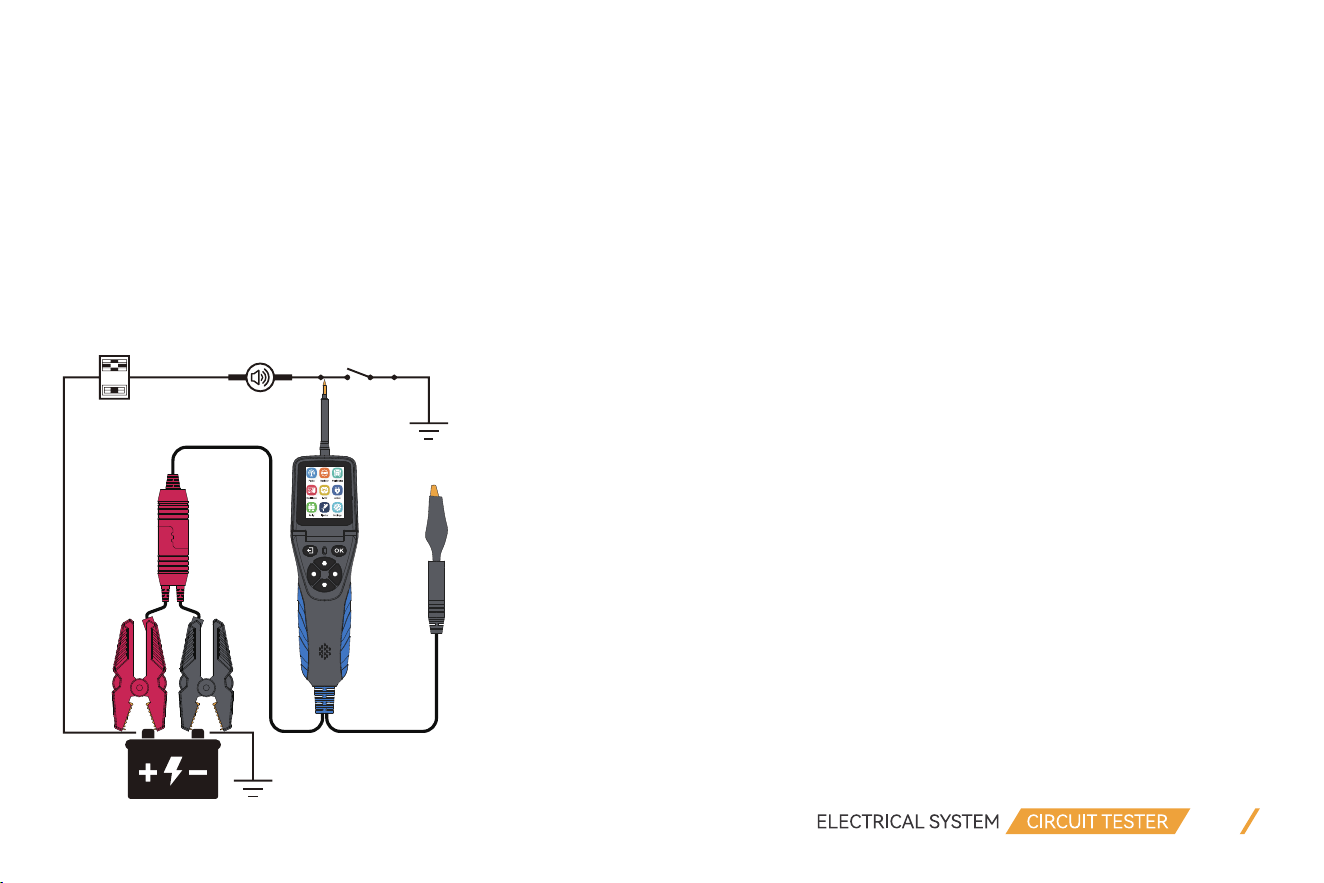
4.7 Following & Locating Short Circuits
In most cases a short circuit will appear by a fuse or a fusible link blowing or an electrical protection device tripping (i.e., a
circuit breaker).
This is the best place to begin the search.
Test Procedure:
(1) Remove the blown fuse from the fuse box.
(2) Use the probe tip to activate and energize each of the fuse contacts.
(3) The contact which trips the circuit breaker is the shorted circuit. Take note of this wire's identification code or color.
(4) follow the wire as far as you can along the wiring harness.
Here is an example of this application:
• If you are following a short in the brake light circuit, you may know that the wire must pass through the wiring harness at
the door sill. Locate the color-coded wire in the harness and expose it.
• While in Active interface, select MOMENT mode. Use the probe tip to contact the marked wire, press the “UP” button to
trigger power supply.
• If the circuit breaker tripped, you have verified the shorted wire.
• Cut the wire and energize each end with the probe tip. The wire end which trips the circuit breaker again is the shorted
circuit and it will lead you to the shorted area.
• Follow the wire in the shorted direction and repeat this process until the short is located.
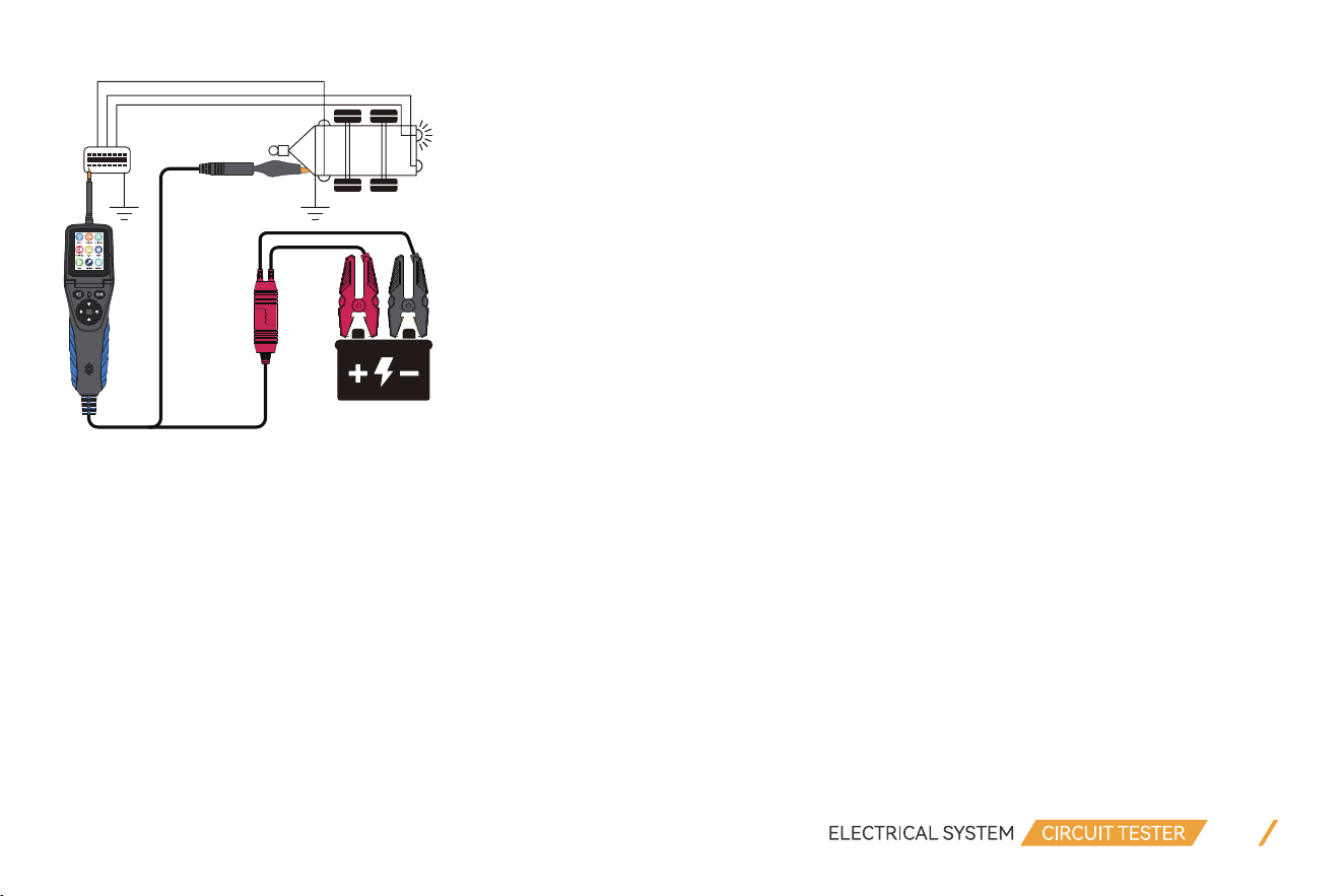
4.8 Trailer Lights and Connection Test
When the probe is in the Multimeter or SMART test, connect the probe auxiliary ground lead to the trailer light, and insert
the probe tip into the OBD socket to display the current voltage. With this method, you can check the function and direction
of the connector and trailer lights. If you find the trailer light connection correctly, you can use the “Component Activation”
function to test whether the trailer light is working or not working.
26
5. Warranty
Limited Three Years Warranty
VDIAGTOOL warrants the V500 product against defects in materials and workmanship for thirty-six (36) months from the
date of delivery to the original purchaser for commercial or business use. This warranty does not cover damage resulting
from misuse, unauthorized modification, improper maintenance, or operation outside specified conditions. VDIAGTOOL's
sole liability shall be limited to repair or replacement of defective components at its discretion. Consequential, incidental, or
other damages are expressly excluded. Some jurisdictions may not permit certain limitations of liability.
6. Contact Us
Warranty & Support
Email: [email protected]
Website: www.vdiagtool.com

27
For wholesale business or become our distributors:
Email: [email protected]
Invent with us, test products before they hit market, help us make better products for everyone:
Email: [email protected]
Create social media content, post online and help our community:
Email: [email protected]
Follow Us on Social Media
Facebook Page: Search for "vdiagtool"
Facebook User Group: Search for "VDIAGTOOL OFFICIAL User Group"
Instagram: Search for "vdiagtool_official"
TikTok: Search for "vdiagtool_us"
YouTube: Search for "Vdiagtool Official"