USER MANUAL
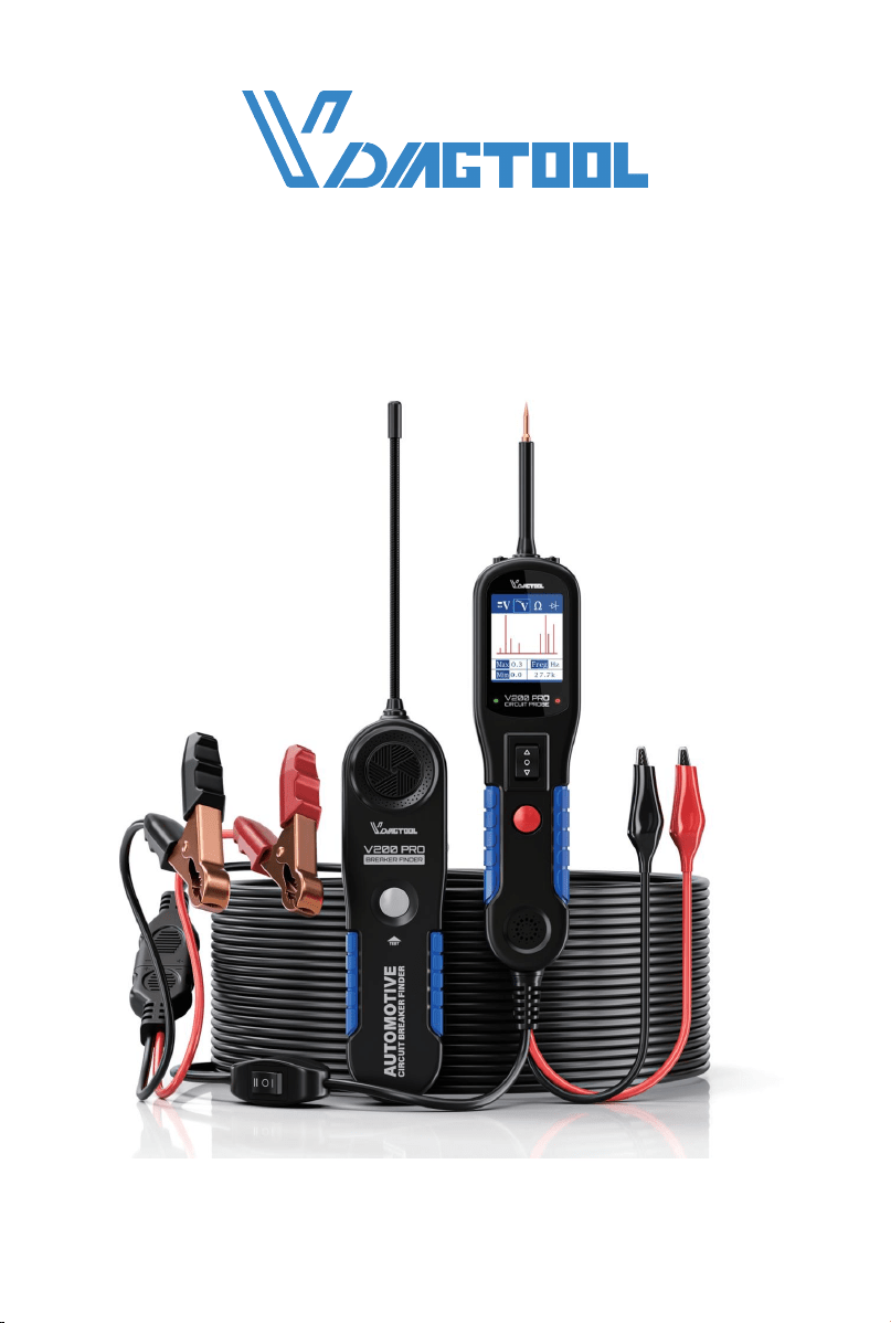
V200 PRO
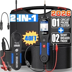
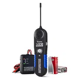
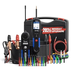
AUTOMOTIVE CIRCUIT PROBE & BREAKER FINDER KIT
www.vdiagtool.com

Safety Information
To ensure your safety and prevent damage to the device or vehicle, please
carefully read and follow all instructions in this manual before use.
When operating the device, always verify proper testing procedures and
strictly adhere to the instructions provided. As automotive electrical
systems may vary, you must assess potential risks and ensure a safe
testing environment.
Always observe all safety warnings, use appropriate tools, and disconnect
power sources when necessary. Improper operation may result in person-
al injury, equipment damage, or voided warranty.
Safety Messages
Safety messages use standardized signal words to indicate hazard levels
and prevent injuries or equipment damage:
DANGER
Will result in death or serious injury if ignored
Indicates an immediately life-threatening hazard.
WARNING
Could result in death or serious injury if ignored
Indicates a potentially dangerous situation.
Safety Instructions
This manual covers known safety hazards, but cannot anticipate all possi-
ble risks. You are responsible for ensuring safe operating conditions and
procedures.
DANGER
• Always ventilate the service area when engine is running or use building
exhaust removal system if available
• Carbon monoxide is odorless and deadly - can cause loss of conscious-
ness or death

WARNINGS
• Always keep a fire extinguisher suitable for gasoline, chemical, and
electrical fires nearby.
• Never operate or observe the tool while driving—distraction can lead to
fatal accidents.
• Keep clothing, hair, hands, tools, and test equipment away from moving
or hot engine parts.
• Perform automotive testing only in a safe, controlled environment.
• Ensure proper ventilation—exhaust gases are poisonous.
• Never connect or disconnect test equipment while the ignition is ON or
the engine is running.
• Place wheel chocks in front of drive wheels and never leave the vehicle
unattended during testing.
• Wear ANSI-approved safety eye protection at all times.
• Exercise extreme caution around ignition coils, distributor caps, spark
plugs, and wires—high voltage is present when the engine is running.
• Before testing, ensure the transmission is in P (A/T) or Neutral (M/T) and
the parking brake is engaged.
• Keep the scan tool clean and dry; avoid contact with oil, water, or grease.
Clean only with a mild detergent and soft cloth.
• Do not modify, disassemble, or expose the tool to extreme temperatures
or moisture.
• This tool is not a substitute for professional diagnostic equipment—use
with caution.
• The manufacturer is not liable for damages caused by misuse, negli-
gence, or unauthorized modifications.
Legal Information
Trademarks
VDIAGTOOL is a registered trademark of Shenzhen VDIAGTOOL Technol-
ogy Co., Ltd in the United States and other jurisdictions. All other product
names mentioned herein may be trademarks of their respective owners.
Copyright Information
© 2017 Shenzhen VDIAGTOOL Technology Co., Ltd. All rights reserved.
No reproduction, distribution, or transmission of this manual is permitted
without express written authorization from VDIAGTOOL. This prohibition

applies to all forms of copying including electronic, mechanical, photo-
copying, and recording.
Disclaimer & Liability Statement
Product Documentation Notice
All illustrations, specifications, and technical data in this manual are for
reference only and subject to change without notice.
For the latest documentation, visit:
https://www.vdiagtool.com/support/downloads
Limitation of Liability
VDIAGTOOL expressly disclaims all liability for:
• Any direct, indirect, incidental, or consequential damages
• Loss of profits or business interruption
• Product modifications or unauthorized use
This manual does not:
• Modify existing purchase/lease agreements
• Create additional liabilities for VDIAGTOOL
• Constitute additional product warranties
IMPORTANT:
Always consult this manual before operation, with special attention to all
safety warnings. VDIAGTOOL reserves the right to modify product specifi-
cations at any time.
Product Support & Training Resources
Technical Support
• Official Website: www.vdiagtool.com
• Support Email: suppor[email protected]
• US Hotline: +1-213-355-7171
• Online Form: https://www.vdiagtool.com/support/tech-support
Training Videos
Free product operation videos:
1. Visit Training Center:
https://www.vdiagtool.com/support/training-center
2. Select Circuit Testers category, then watch model-specific tutorial

V200 Pro Circuit Probe & Breaker Finder
Contents
1. Product Overview................................................................................ 1
1.1 Specifications............................................................................................ 1
1.2 Tool Description....................................................................................... 1
1.3 Included Parts List.................................................................................. 2
2. General Description............................................................................ 3
2.1 Circuit Probe............................................................................................ 3
2.2 Circuit Breaker Finder............................................................................ 3
2.3 Power Supply.......................................................................................... 4
3. Quick Self-Test..................................................................................... 4
4. Circuit Breaker..................................................................................... 5
5. Work Mode.......................................................................................... 6
6. Operating Instructions...................................................................... 7
6.1 Voltage Test.............................................................................................. 7
6.2 Continuity Testing.................................................................................. 8
6.3 Signal Circuit Testing............................................................................. 9
6.4 Activating Components in Your Hand............................................ 10
6.5 Activating Components in the Vehicle........................................... 11
6.6 Testing Trailer Lights and Connections............................................ 12
6.7 Activating Components w/Ground.................................................. 13
6.8 Red/Green Polarity LED...................................................................... 14
6.9 Following & Locating Short Circuits................................................ 14
6.10 Checking for Bad Ground Contacts............................................... 15
7. Circuit Breaker Finder Safety Information.................................. 16
8. Locating Open Circuit...................................................................... 16
8.1 Circuit Breaker Finder Operation...................................................... 16
8.2 Sensitivity Adjustment.............................. .......................................... 16
8.3 Breaker Finder Operation Guide...................................................... 17
9. Warranty.............................................................................................. 18
10. Contact Us......................................................................................... 18
1
V200 Pro Circuit Probe & Breaker Finder
1. Product Overview
1.1 Specifications
1.2 Tool Description
V200 Pro Circuit Probe
Display TFT Color Display (168×128 dpi)
DC Voltage Range 0V – 65V ±1 Digit
Resistance Range
0 – 100 kΩ
Material Plastic Housing
Operating Temperature 0°C to 60°C (32°F to 140°F)
Storage Temperature -40°C to 70°C (-40°F to 158°F)
External Power
12V/24V DC (Vehicle Battery)
Dimensions (L × W × H) 188 × 48 × 25 mm (7.4 × 1.88 × 0.98 in)
V200 Pro Breaker Finder
DC Voltage Range 6V - 24V
Operating Voltage 9V (Internal Battery)
Probe Length 72 mm (2.83 in)
Material Plastic Housing + Flexible Metal Probe
Operating Temperature 0°C to 60°C (32°F to 140°F)
Storage Temperature -40°C to 70°C (-40°F to 158°F)
Dimensions (L × W × H) 184 × 48 × 24 mm (7.24 × 1.88 × 0.94 in)

2
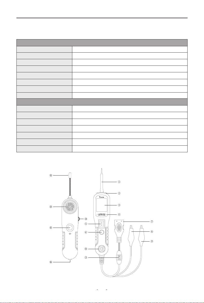
V200 Pro Circuit Probe & Breaker Finder
①Probe Tip - Direct contact point for circuit/component testing
②LED Work Light - Illuminates dark work environments
③LCD Display - Real-time measurement readout
④Polarity Indicator (Red/Green) - Circuit polarity detection:
• Red: Positive voltage detected
• Green: Negative voltage detected
⑤Power Switch - Controls power ON/OFF and current polarity selection
⑥Mode Button - Toggles between:
• AC Voltage • DC Voltage • Resistance • Diode
⑦Battery Adapter - Connects to vehicle battery (12V/24V DC input)
⑧Ground Clip - Provides auxiliary grounding for stable measurements
⑨Positive Lead - Conducts positive current
⑩Audio Alarm - Provides audible alerts
⑪Tool Kit Working Mode Switch - Switches between:
• I: Circuit Probe • II: Breaker Finder
⑫RF Antenna - Receives wireless signal data
⑬Buzzer - Audible continuity indicator
⑭Sensitivity Adjust - Calibrates detection sensitivity
⑮Test Trigger - Initiates diagnostic sequence
⑯3.5mm Audio Jack - External headphone connection
1.3 Included Parts List
Part Qty
User Manual 1
12V/24V Cigarette Lighter Adapter 1
Battery Clips (Red/Black) 1
Replaceable Probe Tip 1
20ft Test Lead Extension 1
Impact-Resistant Storage Case 1
Power Assist Cable 1
Breaker Finder 1

3
V200 Pro Circuit Probe & Breaker Finder
2. General Description
2.1 Circuit Probe
The V200 Pro Circuit Probe is an advanced electrical diagnostic tool
designed to reduce troubleshooting time in 6-30V vehicle electrical
systems. With its quick battery connection, this tool enables:
Key Features & Benefits:
◆
Instant Polarity Detection
• Visually identify positive and negative (via LED indicators) without
switching battery connections.
◆
Built-in Continuity Testing
• Use the auxiliary ground lead to verify circuit integrity without addition-
al tools.
◆
Direct Component Activation
• Press the power switch to apply positive/negative current to the probe
tip—eliminating jumper wires for relay, switch, or sensor testing.
◆
Ground Fault Detection
• Instantly detect poor ground connections—no voltage drop calcula-
tions required.
◆
Short-Circuit Protection & Tracing
• Integrated circuit breaker protects against overloads.
• 20ft cable (6.1m) allows full-vehicle short-circuit tracing without fuse
replacement.
◆
Universal Compatibility
• Works on all 6V, 12V, and 24V vehicle systems.
2.2 Circuit Breaker Finder
The professional-grade tool detects and locates electrical faults in 6-42V
DC systems with these capabilities:
Core Functions:
• Instantly identifies open circuits, broken wires, and poor connections
• Traces wire paths and detects current leaks
• Diagnoses intermittent faults by monitoring tone changes when flexing
wires/connectors
Key Features:
• Wide voltage range (6-42V DC) for automotive, truck, tractor, RV, and
marine use
• High-sensitivity receiver for precise fault pinpointing

4
V200 Pro Circuit Probe & Breaker Finder
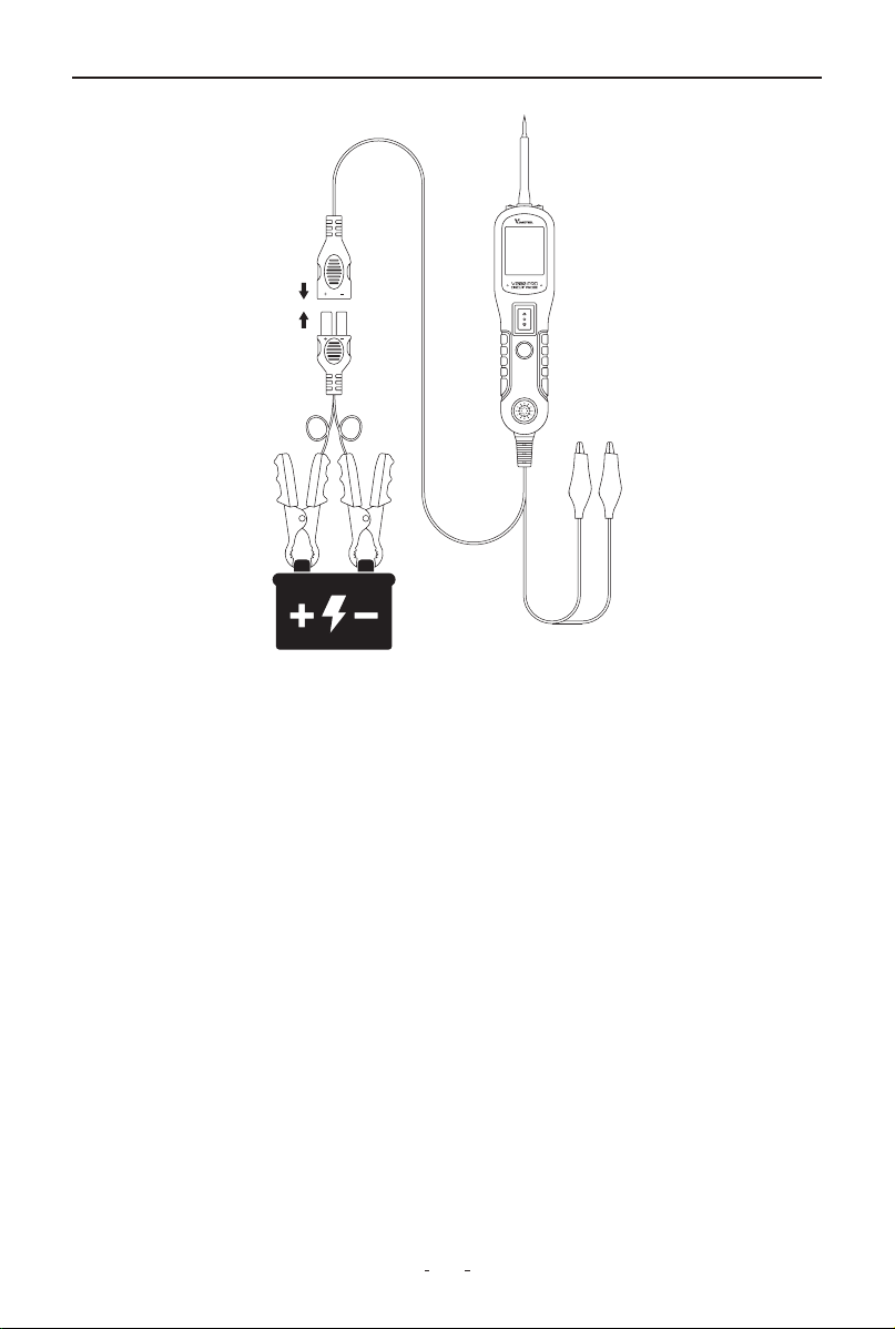
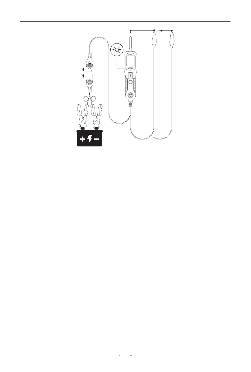
2.3 Power Supply
The tool is powered by connecting directly to the vehicle battery - attach
the red clamp to the positive terminal and the black clamp to the nega-
tive terminal. Upon successful connection, the tool will emit a confirma-
tion beep and automatically activate its headlights to illuminate the work
area.
3. Quick Self-Test
Before testing any circuit or component, perform this quick self-test to
verify tool functionality:
(1) Connect the tool to the vehicle battery.
(2) Set Mode Switch to Mode I (Circuit Probe mode).
(3) Test Power Switch (momentary rocker switch with ± markings):
• Press forward (+):
- Red LED illuminates
- LCD displays battery voltage (e.g., 12.0V)
- Audible beep activates
• Release: All indicators turn off
• Press backward (–):
- Green LED illuminates
- LCD shows 0.0V (ground)
- Audible beep activates
• Release: All indicators turn off
Validation: If LEDs, display, and buzzer respond as described, the tool is
operational.
5
V200 Pro Circuit Probe & Breaker Finder
Note: The momentary voltage display change from ~12V to 0V when
releasing the switch is normal - this first shows the battery voltage, then
indicates an open circuit when no component is connected.
Important: To extend switch lifespan, always press the power switch
before contacting the probe tip to components. This ensures any arcing
occurs at the tip rather than the switch contacts.
4. Circuit Breaker
The tool features built-in short-circuit protection with an auto-reset
circuit breaker that trips during overloads, serving as both a safety
mechanism and diagnostic aid.
When tripped, the breaker cuts power output while maintaining all other
functions - you can still test circuits and read voltages, but battery
current won't flow to the probe tip even if the power switch is pressed.
This design provides dual protection: preventing tool damage from
overloads while creating a failsafe mode for sensitive electronics testing.

6
V200 Pro Circuit Probe & Breaker Finder
Technicians can intentionally trip the breaker as an extra precaution
when working on delicate circuits, effectively disabling power output
while preserving measurement capabilities.
The auto-reset function ensures continuous protection - simply release
the power switch to restore normal operation after troubleshooting.
This intelligent protection system allows safe testing in all scenarios while
preventing accidental damage to vehicle electronics.
5. Work Mode
The tool offers four diagnostic modes, which can be selected by pressing
the Mode button to cycle through them.
DC voltage
In this mode, touch the probe tip to a circuit. The LCD will display the DC
voltage with 0.1V resolution.
AC voltage
In this mode, touch the probe tip to a circuit. The LCD will display the
maximum voltage, minimum voltage, and frequency.
12.1V
Max 17.9 Freq Hz
Min 0.3 50
7
V200 Pro Circuit Probe & Breaker Finder
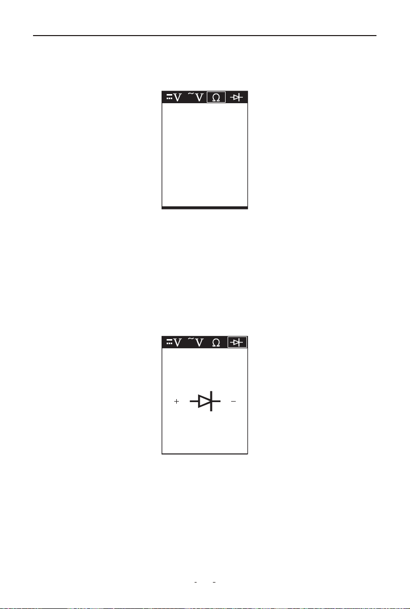
Resistance
In this mode, touch the probe tip to a circuit. The LCD will show the resis-
tance between the probe tip and the auxiliary ground lead.
Diode
In this mode:
• Connect the probe tip to the positive terminal of the diode.
• Connect the auxiliary ground lead to the negative terminal.
• The screen will display the forward voltage drop, indicating correct
forward bias.
• If you reverse the connections (tip to negative, ground lead to positive),
the screen will not display a voltage, indicating correct reverse bias.
6. Operating Instructions
6.1 Voltage Test
In DC Voltage mode, the probe tip detects circuit status with 0.1V resolu-
tion:
• Contact with a positive circuit activates the red LED, displays voltage
(e.g. 12.3V), and sounds a confirmation beep
11.7Ω
73.3Ω
Forward Bias
( ) ( )
8
V200 Pro Circuit Probe & Breaker Finder
• Contact with a negative circuit activates the green LED, displays voltage
(e.g. -12.3V), and sounds a confirmation beep
• An open circuit shows no LED activation while maintaining 0.1V mea-
surement precision.
6.2 Continuity Testing
In Resistance mode, the probe tip and auxiliary ground lead enable
continuity testing of both connected and disconnected circuits:
Test Interpretation:
• Good continuity (≤1Ω):
Displays "0.0Ω" + green LED + continuous beep
9
V200 Pro Circuit Probe & Breaker Finder
• Measurable resistance (1Ω-100kΩ):
Shows actual resistance value
• Open circuit (>100kΩ):
Displays "OL" (Over Limit)
Alternative Ground Verification:
Briefly activate power switch - circuit breaker tripping confirms a low-re-
sistance (<1Ω) ground/battery connection.
Important:
The insulated probe tip safely pierces wires (up to 18AWG) for in-circuit
testing without disassembly.
6.3 Signal Circuit Testing
When you retrieve a DTC related to a sensor circuit (like a MAP sensor),
you can quickly test the circuit as follows:
(1) Set your diagnostic tool to AC Voltage mode. Connect the probe tip
to the sensor's positive terminal and attach the ground lead.
(2) Connect a vacuum pump to the MAP sensor.
(3) With the probe touching the sensor's positive terminal, observe the
LCD display - it should show a sine wave under normal conditions.
(4) Apply vacuum to the sensor.

10
V200 Pro Circuit Probe & Breaker Finder
(5) Release the vacuum and monitor the LCD readings.
If the readings are abnormal, there is likely an issue with the sensor.
Note: Always refer to your specific diagnostic tool's manual for exact
procedures.
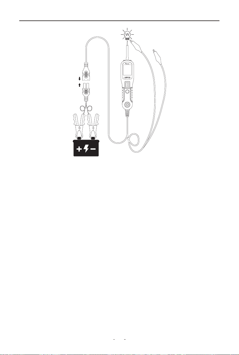
6.4 Activating Components in Your Hand
The tool allows you to test and activate handheld components such as
bulbs, motors, or relays directly. This function helps verify component
functionality before installation or during troubleshooting.
To perform the test, follow these steps:
(1) Connect the auxiliary ground lead to the negative terminal or ground
side of the component.
(2) Touch the probe tip to the positive terminal of the component. The
display will show green, confirming continuity through the component.
(3) Briefly press and release the power switch forward. If the display
changes from green to red, the component is ready for activation.
(4) Hold the power switch forward to deliver power to the component.
Current will flow from the tool's probe through the component and back
via the ground connection.
For example, when testing a bulb:
(1) Connect the ground clip to the bulb's base (negative side).
(2) Touch the probe tip to the bulb's center contact (positive side).
(3) Hold the power switch forward to illuminate the bulb.
Max 12.4 Freq Hz
Min 0.2 43.0K
11
V200 Pro Circuit Probe & Breaker Finder
If the display turns off or the circuit breaker trips, the tool has detected
an overload.
This could happen because:
(1) The contact you're probing is direct ground or negative voltage
(2) The component being tested is short-circuited
(3) It's a high-current component (e.g. starter motor)
To reset, simply wait about 15 seconds for the breaker to cool down
before continuing testing.
6.5 Activating Components in The Vehicle
To safely activate components while installed in the vehicle, first set the
tool to DC Voltage mode and touch the probe tip to the component's
positive terminal. The display will show green if proper ground continuity
exists. Briefly press and release the power switch - if the display changes
from green to red, it is safe to proceed with activation. If the display turns
off or the protection activates immediately, this indicates an overload
condition.
This could happen for the following reasons:
(1) The contact you are probing is a direct ground
(2) The component you are testing is short-circuited
12
V200 Pro Circuit Probe & Breaker Finder
(3) The component is a very high current component (i.e., starter motor)
If the circuit breaker trips, wait 15 seconds for it to reset automatically.
WARNING:
Improper voltage application may damage sensitive vehicle electronics.
Always consult the manufacturer's wiring diagrams and diagnostic
procedures before testing.
NOTE:
To prolong switch life, press and hold the power switch before contacting
the component. This directs any electrical arcing to the probe tip rather
than the switch contacts.
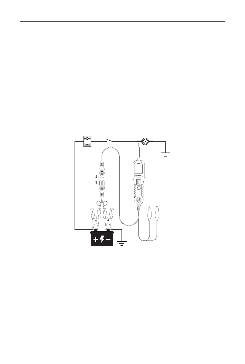
6.6 Activating Components w/Ground
To activate components using ground connection, begin by setting the
tool to DC Voltage mode and touching the probe tip to the component's
negative terminal. The display will show red when a valid ground
connection is detected. Briefly press and release the power switch back-
ward - if the display changes from red to green, you may proceed with
activation. If the display turns off or the protection activates, this
indicates an overload condition.
This could happen for the following reasons:
(1) The contact you are probing is a direct positive voltage source
13
V200 Pro Circuit Probe & Breaker Finder
(2) The component you are testing is short-circuited
(3) The component is a very high current component (e.g., starter
motor)
If the circuit breaker trips, wait 15 seconds for it to reset automatically.
WARNING:
When using this function, applying ground to a protected circuit may
blow or trip the vehicle's fuse.
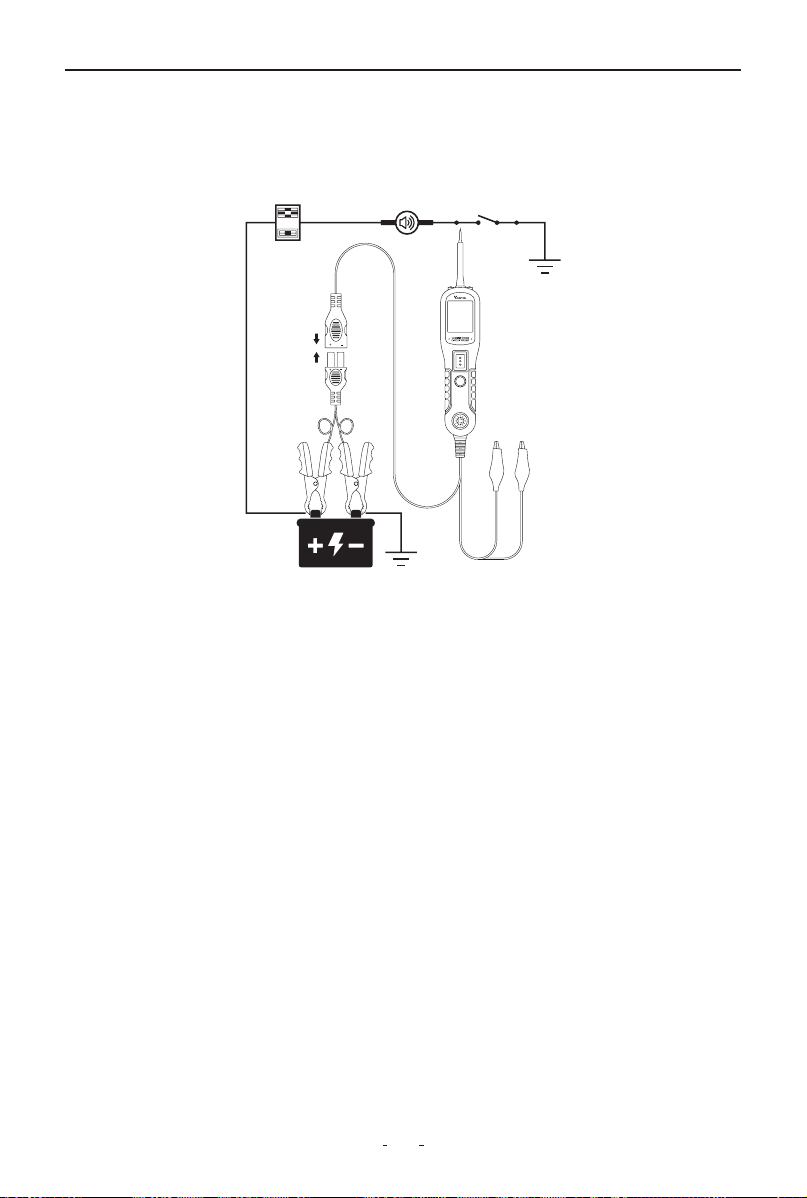
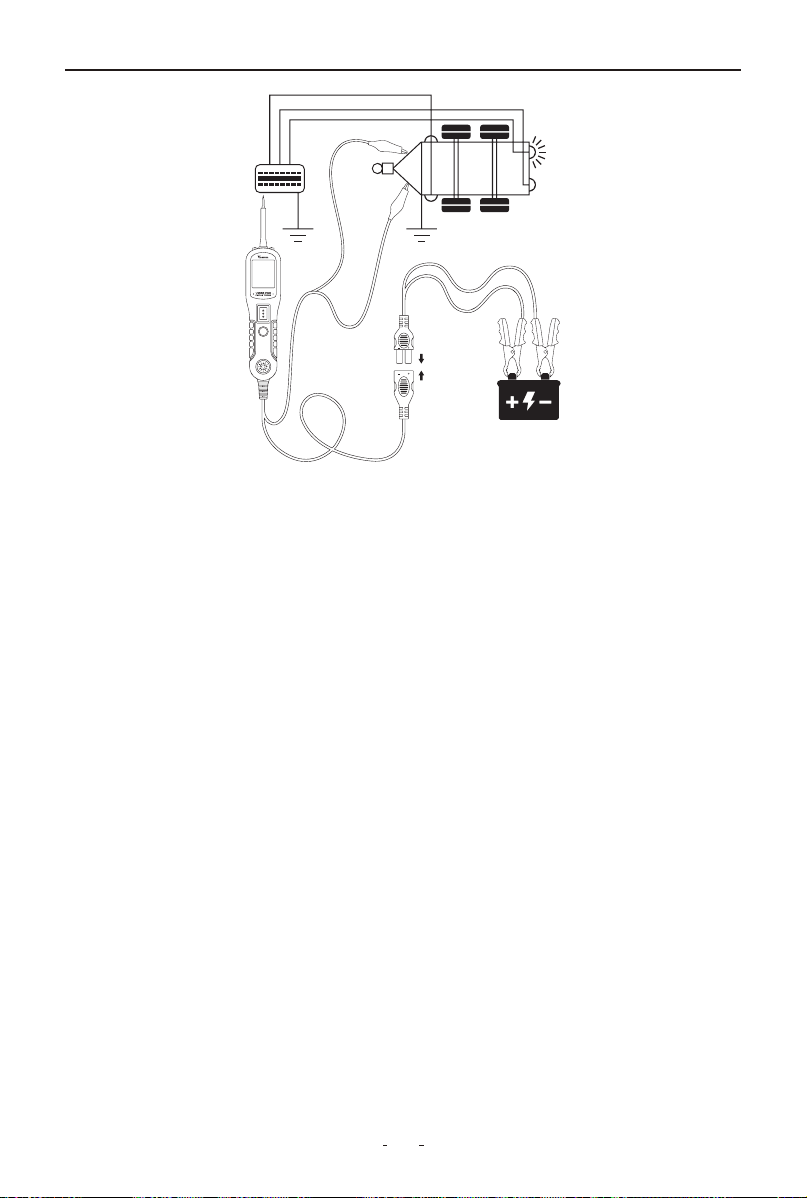
6.7 Testing Trailer Lights and Connections
When the tool in DC Voltage mode, clip the auxiliary ground lead to the
trailer ground, probe the contacts at the jack and then apply voltage to
the probe tip. This allows you check the function and orientation of the
connector and trailer lights.
If the circuit breaker tripped, that contact is likely a ground. Reset the
circuit breaker by letting it cool down for 15 seconds.
14
V200 Pro Circuit Probe & Breaker Finder
6.8 Red/Green Polarity LED
The Red/Green Polarity LED lights up when the probe tip voltage match-
es the battery within ±0.4 volts. It is added information that could be
valuable to the technician.
If the circuit you are testing is not within a 0.4 volt (plus or minus) of
supply voltage, you will see the voltage reading on the LCD but you will
not hear a tone or see a red or green LED.
This tells you either you have a voltage drop in excess of 0.8 volt from
battery voltage or you are probing a circuit that has an increase of a 0.8
volt or more over battery voltage. To determine battery voltage, simply
remove the tip from the circuit and press the power switch forward.
Battery voltage will then be displayed on the LCD. The difference
between the battery voltage and what is read on the circuit is either
voltage drop or voltage increase. This allows you to determine a voltage
drop without running back to check the battery. It’s just another one of
time saving feature the circuit probe has.
6.9 Following & Locating Short Circuits
When a short circuit occurs, it usually causes a fuse to blow or a circuit
breaker to trip. This is the best place to start troubleshooting.
(1) Remove the blown fuse from the fuse box.
(2) Use the probe tip to energize each fuse terminal. The terminal
that trips the tool’s circuit breaker indicates the shorted circuit. Take

15
V200 Pro Circuit Probe & Breaker Finder
the wire’s color or identification code.
(3) Follow the wire along the harness as far as possible. Pierce the
insulation with the probe tip and press the power switch forward.
(4) If the circuit breaker trips, the short is in that direction.
(5) Cut the wire and energize both ends. The end that trips the breaker
again leads to the short. Repeat this process until the fault is located.
Example:
If there’s a short in the brake light circuit, start at the fuse box. Identify
the brake light circuit wire by its color. Probe along the harness, such as
through the door sill area, where wires often run. Energize the wire
step-by-step. When the circuit breaker trips, you’ve confirmed the short
is in that direction. Cut the wire if necessary and continue probing both
sides until the fault is located.
6.10 Checking for Bad Ground Contacts
The tool can help quickly verify whether a ground contact is good or
faulty.
(1) Use the probe tip to contact the suspected ground point (such as a
ground wire, chassis, or connector).
(2) Check the screen display:
If the screen turns green and a beep sounds, the point likely has a
ground connection.
(3) To confirm, press the power switch forward briefly, then release it:
• If the the screen turns red and a beep sounds, this means the point is
not a true ground—it has voltage or a bad connection.
• If the circuit breaker trips, it confirms that the point is a solid ground,
because the tool delivered battery voltage to ground, causing the
protection to activate.
Note: The circuit breaker may also trip if the point is connected to a
high-current component (e.g., starter motor), which is normal in that
case.
16
V200 Pro Circuit Probe & Breaker Finder
7. Circuit Breaker Finder Safety Information
Is the Tool Computer and Airbag Safe?
The circuit breaker finder LED and LCD pull no more than 1 millamp of
current, therefore when using it as a test light or multimeter, it is comput-
er and airbag safe. However, pressing the power switch is a different
story. When you press the switch forward, you are conducting full
battery current to the tip of the probe. There is a nice safety feature built
into the tool. Simply connect the extra ground lead to the circuit breaker
finder and press the power switch forward until it trips the circuit breaker.
This will prevent power from going to the tip but still allow you to use the
tool as a multimeter. When you are away from computer components,
simply press the reset button and you are ready to power up again.
8. Locating Open Circuit
8.1 Circuit Breaker Finder Operation
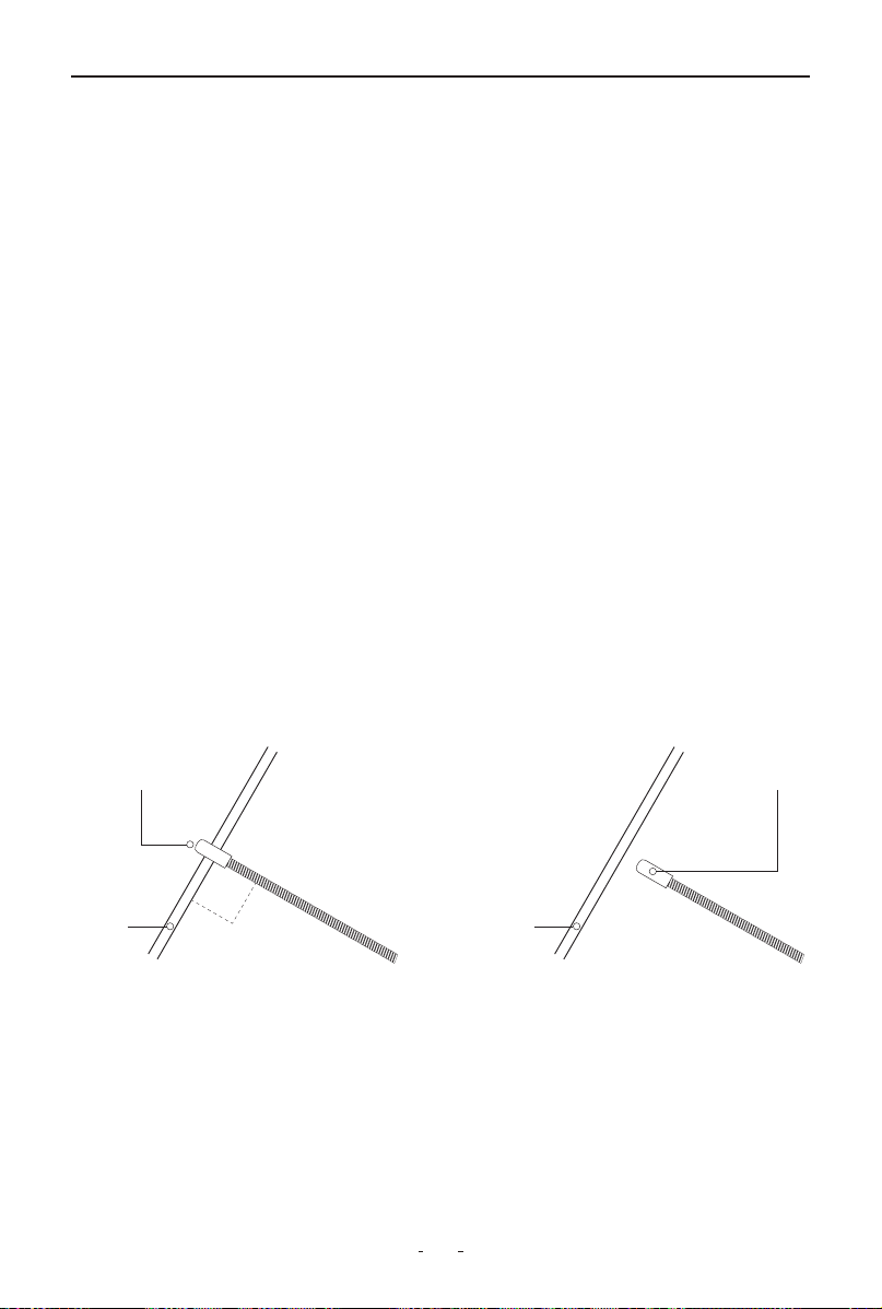
The breaker finder's flexible steel probe can be bent to access wires in
tight spaces. For optimal signal detection:
• Position the probe tip (black cap) perpendicular (90°) to the wire
• Maintain close proximity above or below the wire
Signal pickup range varies based on circuit characteristics and sensitivity
settings.
8.2 Sensitivity Adjustment
Rotate the switch clockwise to increase sensitivity or counterclockwise to
decrease sensitivity.
CORRECT
Sensor
Cable
90°
INCORRECT
Sensor
Cable
17
V200 Pro Circuit Probe & Breaker Finder
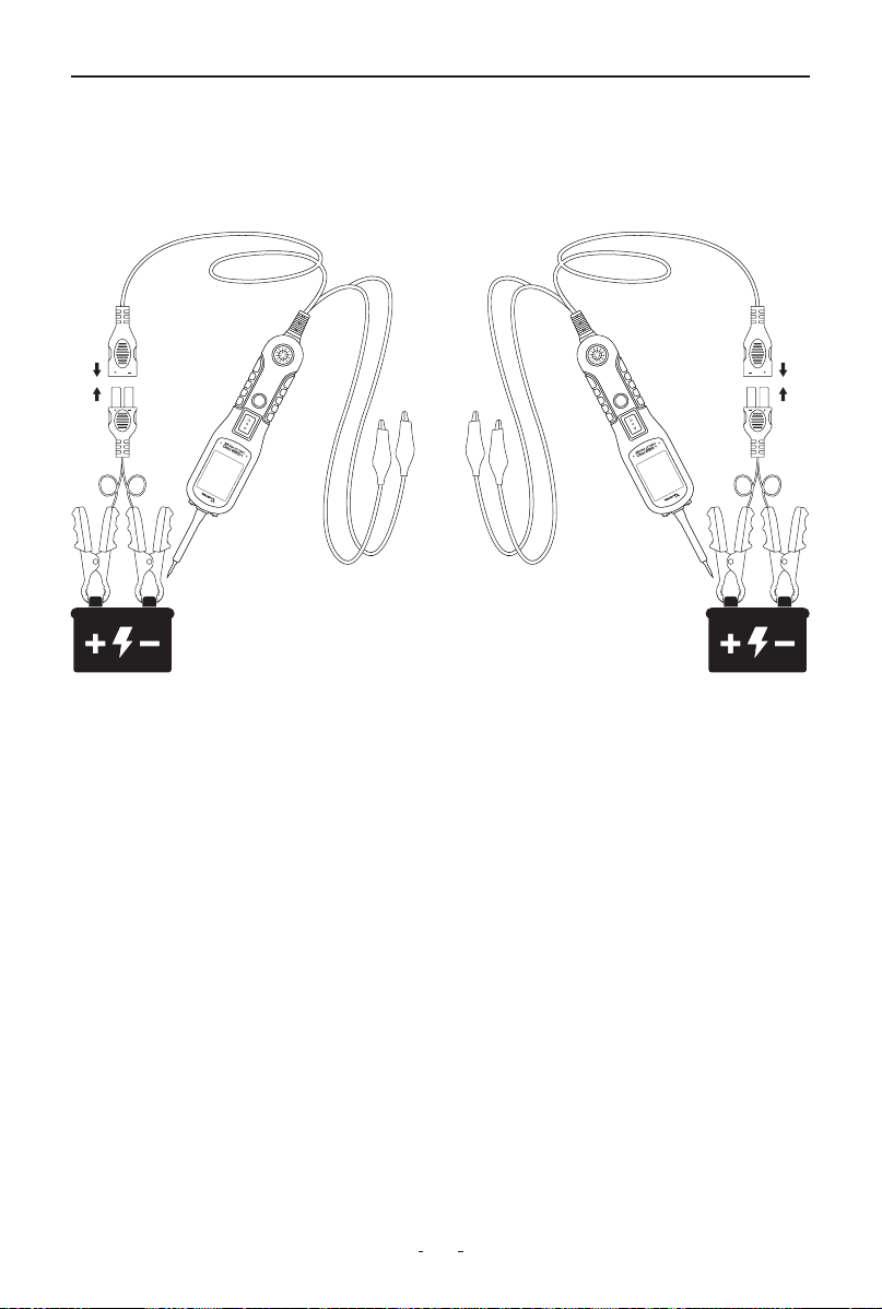
8.3 Breaker Finder Operation Guide
Initial Setup & Function Check
Connect the probe kit to power and select Mode II on the tool kit’s
working mode switch. Turn on the breaker finder and set the rotary
switch to the middle position.
To verify operation, press and hold the TEST button and slide the black
probe tip along a known-good wire—if the loudspeaker emits a tone,
the device is working correctly.
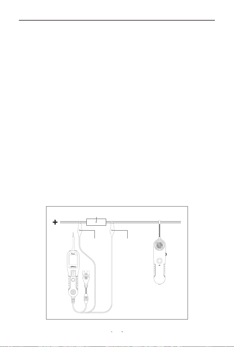
Locating Open Circuits
(1) Connect Test Leads: Attach the black lead to ground (negative) and
the red lead to a positive supply (or a fuse/connector for easier access).
(2) Trace the Wire: With the rotary switch in the middle position, hold
the TEST button and sweep the probe perpendicularly along the wire,
keeping it as close as possible. Start by checking multiple points to
isolate the fault, then trace toward the load end.
(3) Identify the Break: A continuous tone means the circuit is intact;
where the tone stops, the open or bad connection is located.
Adjusting Sensitivity
If no signal is detected, gradually turn the rotary switch clockwise to
increase sensitivity and retest. Once finished, release the TEST button
and disconnect the test leads.
Fuse Socket or Connector
Circuit Probe
Breaker Finder
Black Negative Wire Red Positive Wire

18
V200 Pro Circuit Probe & Breaker Finder
9. Warranty
Limited Three Years Warranty
VDIAGTOOL warrants the V200 Pro product against defects in materials
and workmanship for thirty-six (36) months from the date of delivery to
the original purchaser for commercial or business use. This warranty
does not cover damage resulting from misuse, unauthorized modifica-
tion, improper maintenance, or operation outside specified conditions.
VDIAGTOOL's sole liability shall be limited to repair or replacement of
defective components at its discretion.
Consequential, incidental, or other damages are expressly excluded.
Some jurisdictions may not permit certain limitations of liability.
10. Contact Us
Warranty & Support
Email: suppor[email protected]
Website: www.vdiagtool.com
For wholesale business or become our distributors:
Email: [email protected]
Invent with us, test products before they hit market, help us make
better products for everyone:
Email: [email protected]
Create social media content, post online and help our community:
Email: [email protected]
Follow Us on Social Media

19
V200 Pro Circuit Probe & Breaker Finder
Facebook Page: Search for "vdiagtool"
Facebook User Group: Search for "VDIAGTOOL OFFICIAL User Group"
Instagram: Search for "vdiagtool_official"
TikTok: Search for "vdiagtool_us"
YouTube: Search for "Vdiagtool Official"