Loading ...
Loading ...
Loading ...
Using the Scope and Meter
Input Connections
1
15
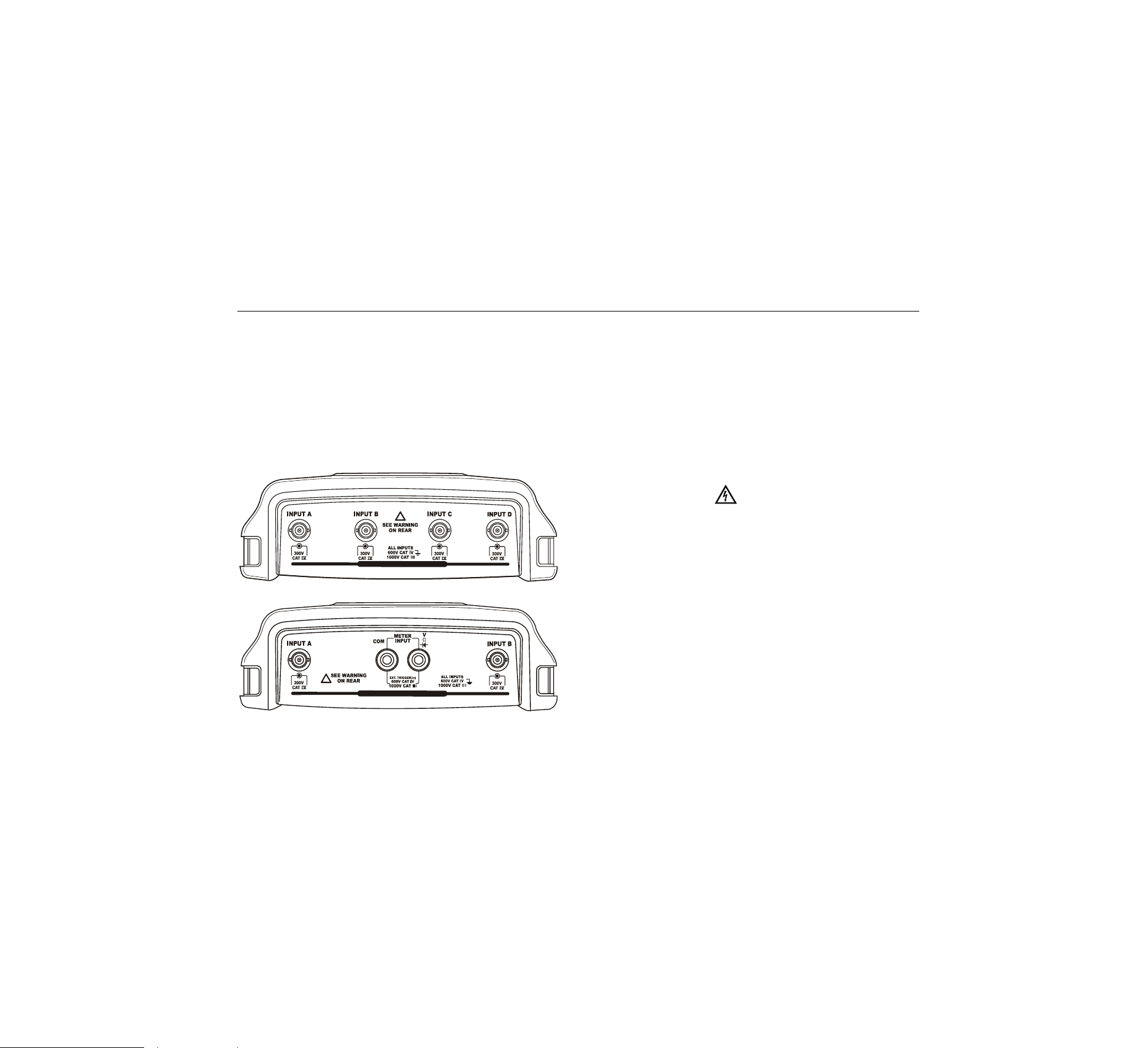
Input Connections
Look at the top of the test tool. The test tool has four
safety BNC jack signal inputs (models 190–xx4), or two
safety BNC jack inputs and two safety 4-mm banana jack
inputs (models 190-xx2).
Isolated input architecture allows independent floating
measurements with each input.
ALL INPUTS ISOLATED
!
ALL INPUTS ISOLATED
!
Figure 5. Measurement Connections
Making Input Connections
To make scope measurements connect the red voltage
probe to input A, the blue voltage probe to input B, the
grey voltage probe to input C and the green voltage probe
to input D. Connect the short ground leads of each voltage
probe to its own reference potential (See Figure 6).
For Meter measurements refer to the applicable section in
this chapter.
Warning
To avoid electrical shock use the insulation
sleeve (Figure 1 item e)) if you use the probes
without the probe tip or the ground spring.
Notes
− To maximally benefit from having
independently isolated floating inputs and to
avoid problems caused by improper use,
read Chapter 6: “Tips”.
− For an accurate indication of the measured
signal, it is necessary to match the probe to
the test tool’s input channel. See section
‘Calibrating the voltage Probes’ in Chapter 7.
1.888.610.7664 sales@GlobalTestSupply.com
Fluke-Direct
.com
Loading ...
Loading ...
Loading ...