Loading ...
Loading ...
Loading ...
NOTE: Make sure that the blade stays flat and centered against the output shaft throughout installation.
CHECKING THE OIL LEVEL
The importance of checking and maintaining the proper oil level in
the crankcase cannot be overemphasized. Check oil before each
use:
1. Stop the engine and allow oil to drain into the crankcase.
2. Place the unit on a level surface to get a proper oil level
reading (Fig. 20).
3. Keep dirt, grass clippings and other debris out of the engine.
Clean the area around the oil fill plug before removing it.
4. Remove the oil fill plug.
5. Look into the oil fill hole, use a flashlight if needed. The oil
should be just touching the inner most thread (Fig. 20).
6. If the oil level is not touching the inner most thread on the oil
fill hole, add a small amount of oil to the oil fill hole and
recheck (Fig. 21). Repeat this procedure until the oil level
reaches the inner most thread on the oil fill hole.
NOTE: Do not overfill the unit.
NOTE: Make sure the O-ring is in place on the oil fill plug when
checking and changing the oil (Fig. 8).
CHANGING THE OIL
For a new engine, change the oil after the first 10 hours of
operation. Change the oil while the engine is still warm. The oil will
flow freely and carry away more impurities.
1. Unplug spark plug boot to prevent accidental starting.
2. Remove the oil fill plug.
3. Pour the oil out of the oil fill hole and into a container by
tipping the unit to a vertical position (Fig. 22). Allow ample
time for complete drainage.
4. Wipe up any oil residue on the unit and clean up any oil that
may have spilled. Dispose of the oil according to Federal,
State and local regulations.
5. Refill the crankcase with 3.04 fluid ounce (90 ml or 3/8 cup) of
SAE 30 SF, SG, SH oil.
NOTE: Use the bottle and spout saved from initial use to measure
the correct amount of oil. The top of the label on the bottle measures approximately 3.04 ounces
(90 ml) (Fig. 21). Check the level, See Checking the Oil Level. If the level is low, add a small
amount of oil and recheck. Do not overfill (Fig. 20).
6. Replace the oil fill plug.
7. Reconnect the spark plug boot.
AIR FILTER MAINTENANCE
Cleaning the Air Filter
Clean and re-oil the air filter every 10 hours of
operation. It is an important item to maintain. Failure
to maintain your air filter properly can result in poor
performance or can cause permanent damage to
your engine.
1. Open the air filter cover. Push the tab on the left
side of the cover in, swing the air filter cover out
and off the air filter housing (Fig. 23).
2. Remove the air filter and the screen that sits
behind it (Fig. 23).
3. Wash the filter in detergent and water (Fig. 24).
Rinse the filter thoroughly and allow it to dry.
4. Apply enough clean SAE 30 motor oil to lightly
coat the filter (Fig. 25).
5. Squeeze the filter to spread and remove excess
oil (Fig. 26).
6. Replace the filter (Fig. 23).
NOTE: If the unit is operated without the air filter, you will VOID
the warranty.
7. Reinstall the air filter cover. Position the tabs on the sides of
the air filter cover onto the slots at the top of the back plate
(Fig. 23).
8. Push the cover in until the tab on the air filter backplate snaps
into place in the slot on the air filter cover (Fig. 23).
5
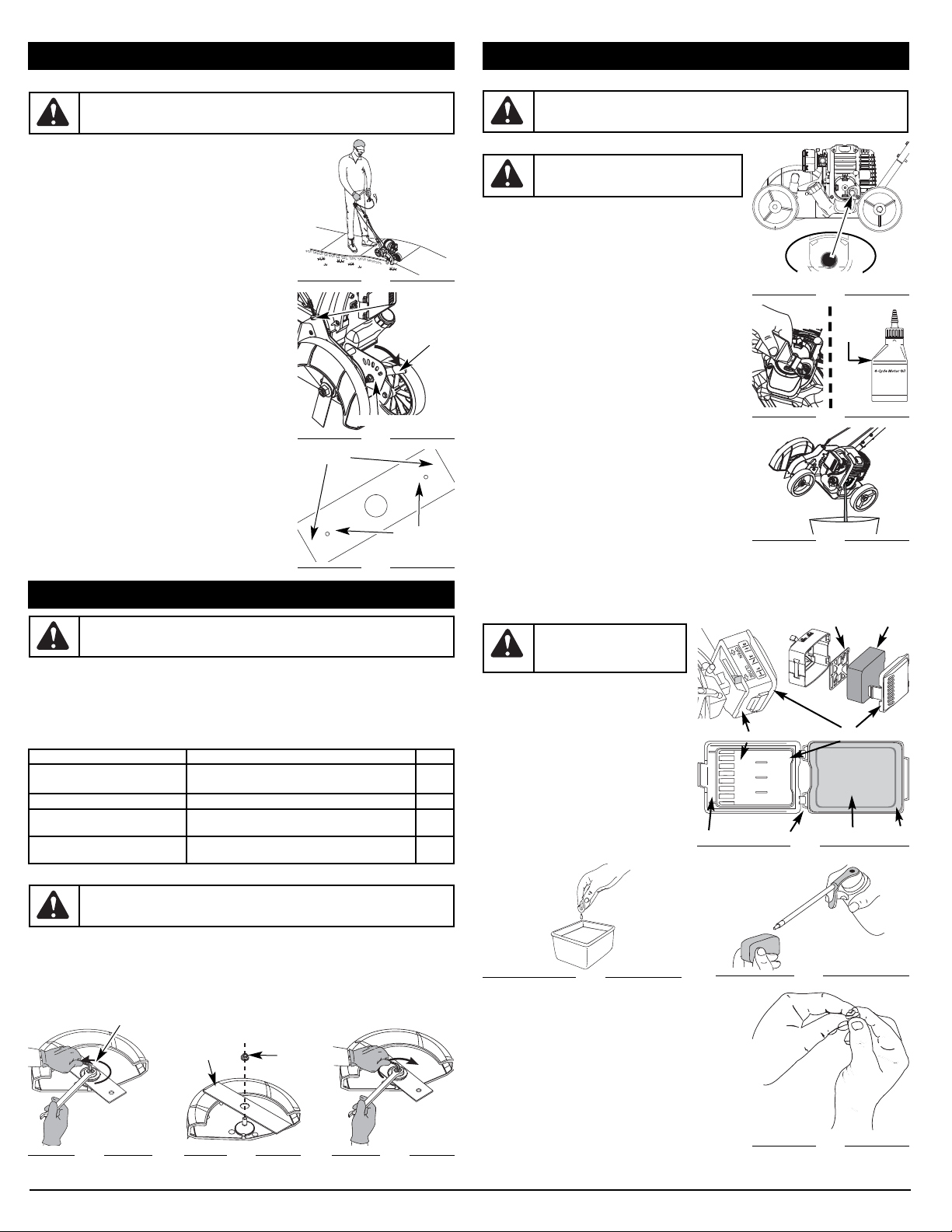
HOLDING THE UNIT
Before operating the unit, stand in the operating position (Fig. 14).
Check for the following:
• The operator is wearing eye protection and proper clothing.
• Both hands are holding the handle bar firmly.
• The edger wheel adjusted for proper cut depth as shown in
Figure 15 and edger positioned as shown in Figure 14.
ADJUSTING EDGER CUTTING DEPTH
1. Grasp the depth adjustment lever located beside the front
wheel (Fig 15).
2. To raise the cutting blade, move the lever toward the front of
the wheel bracket (Fig. 15). Lowering the wheel decreases the
cutting depth.
3. To lower the cutting blade, move the lever toward the rear of
the wheel bracket. Raising the wheel increases the cutting
depth.
TIPS FOR BEST EDGING RESULTS
• Do not force the edger. Edge the first time at a lesser
depth,(No more than 1/2” depth cut per pass), then do the area
again with a deeper setting.
• Walk the edger at a slow, even pace.
• Check the blade condition. As it wears it becomes smaller,
thus reducing the cutting depth performance. Replace with a
new blade when the blade has worn to the blade’s wear limit
holes (Fig. 16).
ADJUST BELT TENSION
If blade fails to turn when the bail is pulled, then:
1. Locate small thumb wheel on top of the belt housing (Fig. 15).
2. Turn the wheel clockwise 1 revolution to increase the tension
on the belt.
3. Try pulling the bail and see if the blade turns. If not, repeat
step 2 until the blade turns.
WARNING:
Always wear eye, hearing, foot and body protection to reduce the risk of
injury when operating this unit.
Fig. 15
Thumb
Wheel
Wheel Bracket
Depth
Adjustment
Lever
Fig. 16
Blade Edges
Wear Limit
Holes
MAINTENANCE AND REPAIR INSTRUCTIONS
MAINTENANCE SCHEDULE
Perform these required maintenance procedures at the frequency stated in the table. These procedures
should also be a part of any seasonal tune-up.
NOTE: Some maintenance procedures may require special tools or skills. If you are unsure about these
procedures take your unit to a Troy-Bilt or other qualified service dealer.
NOTE: Maintenance, replacement, or repair of the emission control devices and system may be
performed by a Troy-Bilt or other qualified service dealer.
WARNING:
To prevent serious injury, never perform maintenance or repairs with unit
running. Always service and repair a cool unit. Disconnect the spark plug wire to ensure
that the unit cannot start.
OPERATING INSTRUCTIONS
Fig. 14
FREQUENCY MAINTENANCE REQUIRED SEE
Before starting engine
Fill fuel tank with fresh fuel
Check oil
p. 4
p. 5
Every 10 hours Clean and re-oil air filter p. 5
1st change at 10 hours
Every 25 hours after
Change oil
Clean spark arrestor
p. 5
p. 6
10 hours on new engine
Every 25 hours
Check rocker arm to valve clearance and adjust
Check spark plug condition and gap
p. 6
p. 6
MAINTENANCE AND REPAIR INSTRUCTIONS
BLADE REPLACEMENT
1. Place the 5/16” Allen wrench in the spindle hole (Fig. 17).
2. While holding the Allen wrench in place, loosen the nut with a 15/16” wrench by turning it
counterclockwise (Fig. 17).
3. Re move the nut and blade. Keep the nut for new blade installation.
4. Install the new blade and nut (Fig. 18).
5. While holding the Allen wrench in the spindle hole, tighten the nut by turning the wrench clockwise
until tight (Fig. 19).
WARNING:
To avoid serious personal injury, always wear gloves while han dling,
removing or in stall ing the blade.
Fig. 17
Loosen
Spindle Hole
Fig. 18
Nut
Edger Blade
Fig. 19
Tighten
WARNING:
Verify the blade is flat against the output shaft after the nut is tightened. If
the blade is off-cen ter, the unit will be dam aged by vibration, and the blade may fly off,
which can cause serious personal in ju ry.
Fig. 20
Max Oil Fill Line
Fig. 22
CAUTION:
Wear gloves to prevent injury
when handling unit.
Fig. 21
Fill Level
WARNING:
To avoid serious
personal injury, always turn the unit
off and allow it to cool before you
clean or service it.
Fig. 23
Screen
Air Filter
Air Filter
Hooks
Tab
Air Filter Cover
Air Filter Housing
Slot
Fig. 24
Fig. 25
Fig. 26
Loading ...
Loading ...
Loading ...