
Loading ...
Loading ...
3
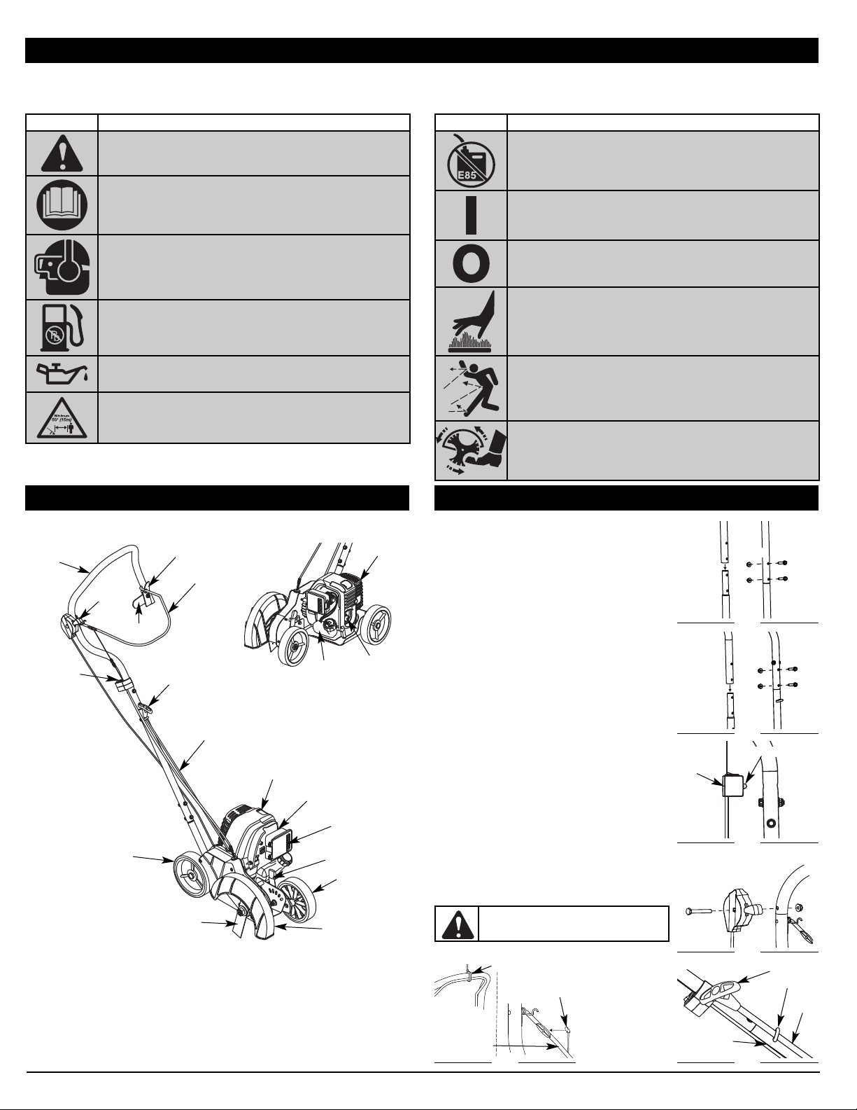
• SAFETY AND INTERNATIONAL SYMBOLS •
This operator's manual describes safety and international symbols and pictographs that may appear on this product. Read the operator's manual for
complete safety, assembly, operating and maintenance and repair information.
RULES FOR SAFE OPERATION
SYMBOL MEANING
• SAFETY ALERT SYMBOL
Indicates danger, warning or caution. May be used in
conjunction with other symbols or pictographs.
• READ OPERATOR'S MANUAL
WARNING: Read the operator’s manual(s) and follow all
warnings and safety instructions. Failure to do so can result
in serious injury to the operator and/or bystanders.
• WEAR EYE AND HEARING PROTECTION
WARNING: Thrown objects and loud noise can cause
severe eye injury and hearing loss. Wear eye protection
meeting ANSI Z87.1 standards and ear protection when
operating this unit. Use a full face shield when needed.
• UNLEADED FUEL
Always use clean, fresh unleaded fuel.
•OIL
Refer to operator’s manual for the proper type of oil.
• KEEP BYSTANDERS AWAY
WARNING: Keep all bystanders, especially children and
pets, at least 50 feet (15 m) from the operating area.
SYMBOL MEANING
• DO NOT USE E85 FUEL IN THIS UNIT
WARNING: It has been proven that fuel containing
greater than 15% ethanol will likely damage this engine and
void the warranty.
• ON/OFF CONTROL
ON / START / RUN
• ON/OFF CONTROL
OFF or STOP
• HOT SURFACE
WARNING: Do not touch a hot muffler, gear housing or
cylinder. You may get burned. These parts get extremely
hot from operation. They remain hot for a short time after
the unit is turned off.
• THROWN OBJECTS AND ROTATING CUTTER CAN
CAUSE SEVERE INJURY
WARNING: Do not operate without the cutting
attachment shield in place. Keep away from the rotating
cutting attachment.
• ROTATING BLADES CAN CAUSE SEVERE INJURY
WARNING:
Stop the engine and allow the blade to stop
before removing the blade, or before cleaning or performing any
maintenance. Keep hands and feet away from rotating blade.
APPLICATIONS
• Edging along paths, driveways, rockeries, etc.
KNOW YOUR UNIT
Handle
Straight Metal Shaft
Throttle
On/Off Switch
Bail Lock
Lever
Bail
Starter Rope Grip
Depth Adjustment Lever
Edger Blade
Blade Shield
Wheel
Wheel
Spark Plug
Air Filter Cover
Choke Lever
Bail Lock
Muffler
Oil Plug
Gas Tank
HANDLE ASSEMBLY
1. Remove the nuts and bolts from the middle handle only, but
not the eyehook.
NOTE: DO NOT remove the bolt and nut in the upper handle.
2. Place the flared end of the middle handle over the lower
handle and align the holes (Fig. 1). Making sure the “TO
START” label is facing up.
3.
Insert two of the bolts previously removed in step 1 into these holes
and thread the lock-nuts onto them until hand tight.
4. Using a 3/8” wrench to hold the bolts, tighten the lock-nuts with
a 7/16” wrench until firm. DO NOT OVERTIGHTEN.
5. Place the flared end of the upper handle onto the end of the
middle handle making sure to align the holes. (Fig. 2)
6.
Insert two of the bolts previously removed in step 1 into these holes
and thread the lock-nuts onto them until hand tight.
7. Repeat step 4 for tightening of this bolt.
8. Extend the switch/ throttle assembly and wires toward the top
of the handle.
9. Align the switch/ throttle control assembly post with the hole
that can be found on the side of the upper handle, (Fig. 3).
10. Firmly push the switch/ throttle assembly onto the upper
handle, making sure that the post slightly protrudes through
the hole on the opposite side.
11. Remove the nut and bolt from the throttle control (Fig. 4).
12. Align the throttle control with the hole on the right side of the
handle.
13. Insert the nut thru both holes
and thread the lock-nuts onto it until
hand tight.
(Fig. 4).
14. Repeat step 4 for tightening of this bolt.
15. Cut the Zip tie holding the bail to the handle (Fig. 5).
16. Insert the Z-Hook into the hole on the right side of the bail to
secure the clutch cable to the bail (Fig. 5).
NOTE: Make sure that the bail wire is on top of the upper handle
and not installed under it.
17. Pull out the starter rope and run it thru the eye hook (Fig. 6).
18. Tighten the nut onto the eye hook using a 7/16” wrench to
tighten. DO NOT OVERTIGHTEN.
19. Using the zip ties found in the hardware bag, secure the
handle cables to the lower and middle handle between the eye
hook and the motor housing.
Fig. 4
Bolt
Nut
Throttle Control
WARNING:
DO NOT run any control wires
though the eye hook. As this may prevent certain
safety features from working properly.
Fig. 1
Lock-Nut
Bolts
Lower
Handle
Middle
Handle
Fig. 2
Upper
Handle
Middle
Handle
Lock-Nut
Bolts
Fig. 3
Post
Switch/
Throttle
Assembly
Upper
Handle
Fig. 6
Eye Hook
Starter
Rope
Lock-Nut
Starter Rope Handle
Fig. 5
Bail
Z-Hook
Zip Tie
ASSEMBLY INSTRUCTIONS
Loading ...
Loading ...
Loading ...