Loading ...
Loading ...
Loading ...
3.2. ELECTRICAL INSTALLATION
3.2.2 General Connection
1. Remove the service lid
2. Insert the network cable.
3. Follow your connector assembly instruction to patch the network cable.
4. Connect the network cable and verify that the unit powers up and that the network connection is working.
5. Unplug the network cable.
6. Connect devices to the IPA according to sections 3.2.3, 3.2.4 and 3.2.5.
7. Plug in the network cable.
8. Refit the service lid.
3.2.3. Powering External Devices
1. Make sure the external devices require a power supply of 12V DC or 24V DC and that the total power
consumption is less than 12W.
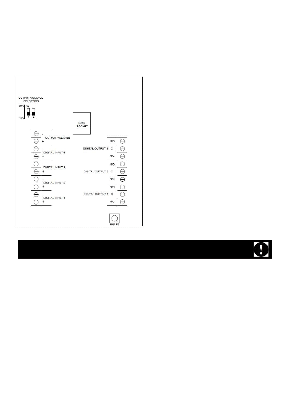
2. Set DIP-switch number 1 to “ON” if the devices require 24V. Leave it at “OFF” it the devices requires 12V.
3. Connect the power cables to the “Power output” terminals according to the markings on the IPA.
4. Connect the network cable and check that the external devices power up.
5. Unplug the network cable and follow the instructions for sections 3.2.2, 3.2.3, 3.2.4 and 3.2.5
3.2.4. Digital Input
1. Make sure the signals comply with the following specification: Max 24V. “Low” signal voltage: 0-1V. “High”
signal voltage: 5-24V. Current typ. 4.4mA@24V.
2. Connect the signal cables to the “Digital input” sockets according to the markings on the IPA. Up to 4 different
digital inputs can be used.
GJD IPA has a short circuit protection to prevent damage on the unit but users should always pay
attention to avoid any connections that may cause short circuit or over load.
Loading ...
Loading ...
Loading ...