
Certifications
IPAnything
GJD519 IPA Controller Designed for IP Systems
1. INTRODUCTION
GJD IPA is a network based I/O device that connects to
your surveillance system. IPA allows you to monitor and
control alarm sensors, measurement devices, sirens, gates
and lights, and integrate connected units to your VMS
system or to allow direct control of network cameras.
1.1. Features
Field of application Convert signals from alarm sensors
or measurement devices to network alarms. Activate units
through network alarms. Powering connected devices.
Digital input 4x digital inputs, high / low / rising edge /
falling edge
Alarm output 3x Relay. Max 30V, 200mA. NC and NO
Power output 1x 12V DC, max 1A or 24V DC, max 0.5A
Network alarms User configurable HTTP web requests
Power supply Power over Ethernet (48V DC)
Power consumption Max 12W, PoE class 3
Operating temperature - 30°C to + 60°C
Interface Ethernet IEEE 802.3af, TCP/IP. Web browser
user interface
Enclosure rating IP65
Color White
Weight 0.3 kg
1.2. Electrical Specifications
Power output 12 VDC, max 1 A or 24 VDC, max 0.5 A.
Short circuit protection.
Digital input Max 24 V. Low signal voltage: 0-1 V. High
signal voltage: 5-24 V.
Current typ. 4.4 mA @ 24 V. Frequency counting: 0.2 Hz-
2.5 kHz.
Frequency accuracy < 1 %.
Digital output Relay, max 30 V, 200 mA. NC and NO.
1.3. Before Operation
The GJD IPA I/O controller is designed to be intuitive and
easy to use, but to ensure best performance all users of
the unit should carefully read this instruction manual
before use.
This manual uses the following warning indications to
pro- vide information regarding usage of the product to
prevent you and others from being harmed and your
assets from being damaged. These warning indications
are described below. Ensure you understand these
precautions before proceeding with the installation.
Warning
Failure to follow the instructions provided by this warning and improper handling may cause
death or serious injury
Caution
Failure to follow the instructions provided by this caution and improper handling may cause
injury and/or property damage
This symbol indicates prohibition. The specific prohibited action is
provided in and/or around the figure.
This symbol requires an
action or gives an instruction.
Warning
Never attempt to disassemble or repair the product. It may cause fire or damage to the devices.
Hold the main unit securely when you install or service it. Exercise care not to bump the product against nearby objects
or drop it inadvertently.
Caution
Ensure the DIP-switches are in correct position for desired power output voltage and analog input
type before powering on the IPA.
Only use approved Power over Ethernet power supplies. Never try to power the device in other ways
than with the RJ45 PoE connection.
Do not touch the unit connections with a wet hand or when the product is wet with rain. It may cause
short circuit and damage the unit.
Clean and check the product periodically for safe use. If any problem is found, contact GJD or
authorised partner to solve the issue before continue using the product.
This product is intended to detect intruders and is not designed to prevent theft, disasters or
accidents. The manufacturer shall not be held liable for any damage to user’s property resulting from
theft, disasters or accidents.
1.4. Precautions
• Make sure the power consumption of all connected devices is below the maximum output power of the IPA.
• Do not install or leave the product in a location exposed to heat, vibration or impacts.
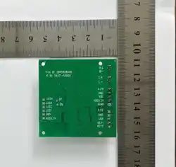
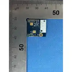
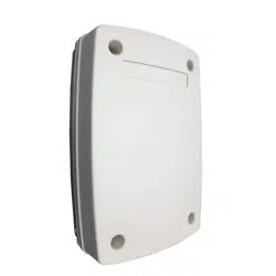
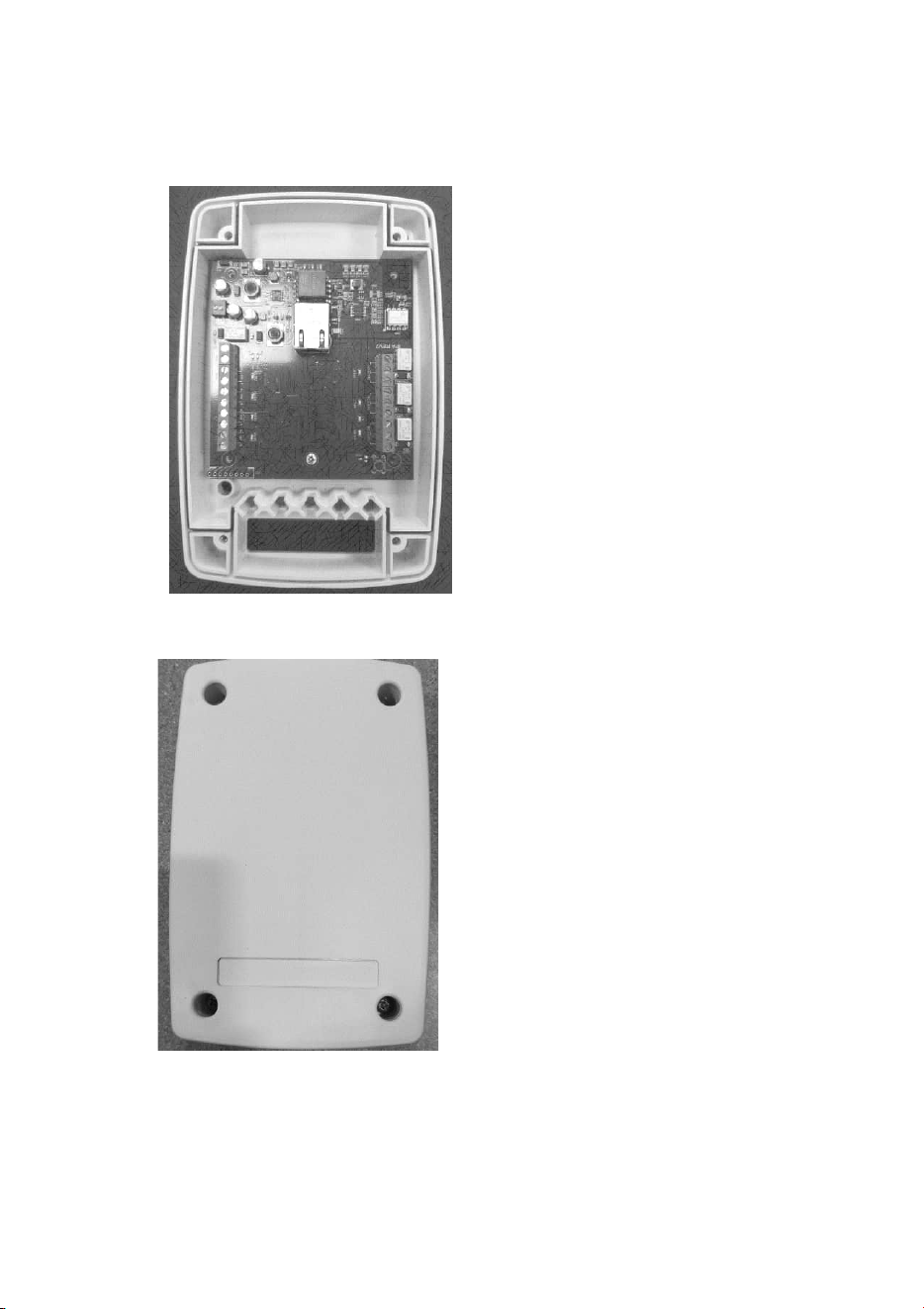
1.5. Part identification
IPA Housing Base and Control PCB
IPA Service Lid

2. GENERAL APPLICATIONS
2.1. Integrate Alarm Sensors
GJD IPA has a 12V supply to power connected alarm sensor and four digital alarm inputs. Each input can be
used to create network alarms directly to VMS, IP cameras or other network devices. Let your line detectors, IR
sensors, microwave barriers, fence alarms or buried sensors be truly integrated parts in your video surveillance
system. With the unit connected to an IPA, installation and integration is just as easy as with IP cameras.
2.2. Control Equipment
Allow sirens, warning lights and lighting to be controlled over the network, either from your VMS system, from
other devices or from sensors connected to the IPA. Three relay outputs offer the option of controlling multiple
devices or to control devices with separate on and off signals.
With the 12V output, devices with low power consumption, such as sirens and warning lights, can be powered
directly by the IPA.
The IPA can be used to create simple IP measurement solutions with only a sensor connected to the IPA and a
camera, but it can as well be used in large-scale industrial applications where critical parts of the process have
monitoring cameras connected to a VMS.
3. INSTALLATION
3.1. Mount the Unit
3.1.1. Mount on Walls etc
Most types of screws can be used. Make sure the screw head fits in the counterbore on the base. If the service lid
doesn’t fit properly the unit will not be waterproof.
3.2. ELECTRICAL INSTALLATION
3.2.2 General Connection
1. Remove the service lid
2. Insert the network cable.
3. Follow your connector assembly instruction to patch the network cable.
4. Connect the network cable and verify that the unit powers up and that the network connection is working.
5. Unplug the network cable.
6. Connect devices to the IPA according to sections 3.2.3, 3.2.4 and 3.2.5.
7. Plug in the network cable.
8. Refit the service lid.
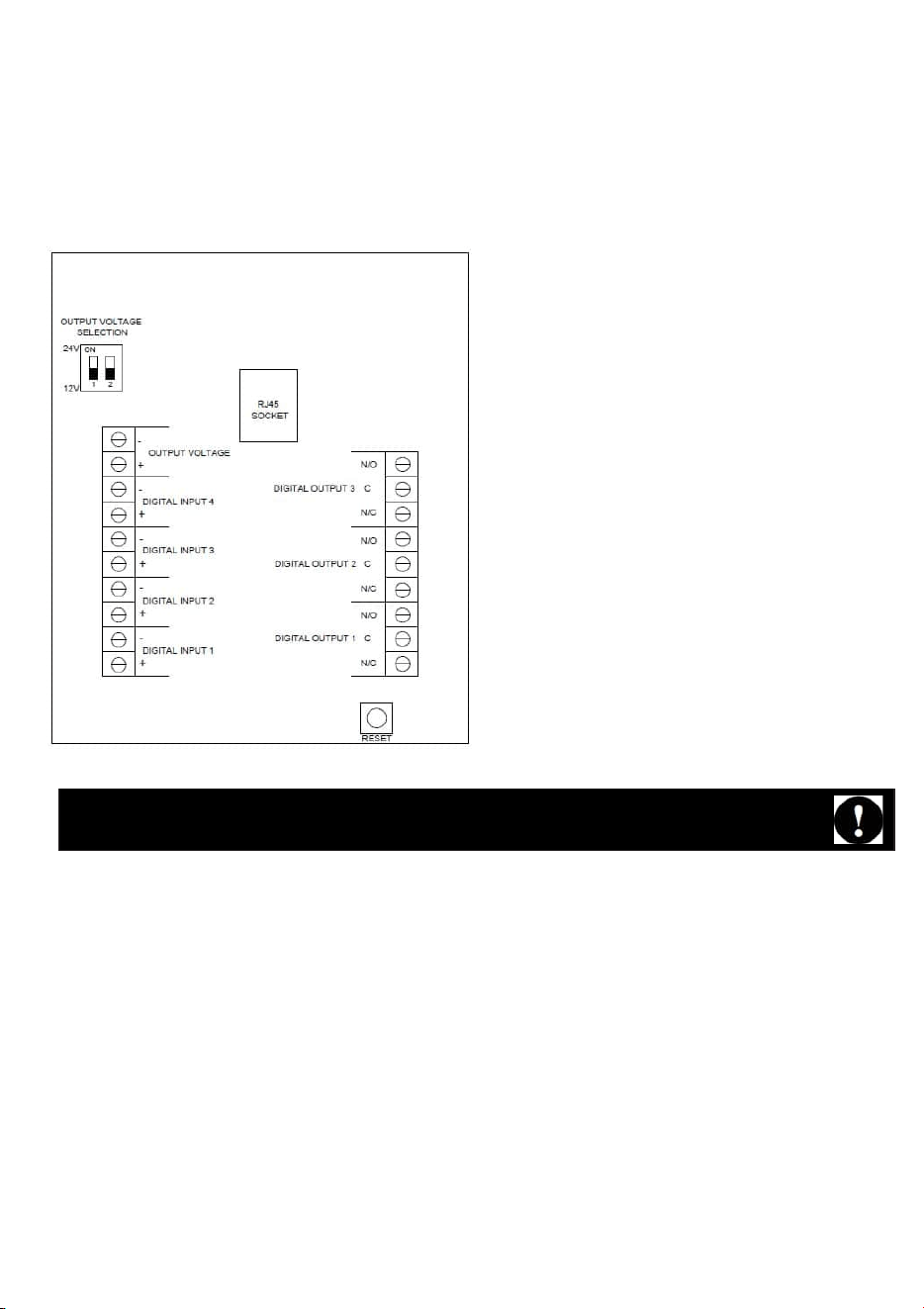
3.2.3. Powering External Devices
1. Make sure the external devices require a power supply of 12V DC or 24V DC and that the total power
consumption is less than 12W.
2. Set DIP-switch number 1 to “ON” if the devices require 24V. Leave it at “OFF” it the devices requires 12V.
3. Connect the power cables to the “Power output” terminals according to the markings on the IPA.
4. Connect the network cable and check that the external devices power up.
5. Unplug the network cable and follow the instructions for sections 3.2.2, 3.2.3, 3.2.4 and 3.2.5
3.2.4. Digital Input
1. Make sure the signals comply with the following specification: Max 24V. “Low” signal voltage: 0-1V. “High”
signal voltage: 5-24V. Current typ. 4.4mA@24V.
2. Connect the signal cables to the “Digital input” sockets according to the markings on the IPA. Up to 4 different
digital inputs can be used.
GJD IPA has a short circuit protection to prevent damage on the unit but users should always pay
attention to avoid any connections that may cause short circuit or over load.
3.2.5. Digital Output
1. Make sure the connected device for each output complies with the following specification: Max 30V, 200mA.
2. Each digital output can be used as normally closed (NC) and normally open (NO).
3. Connect the cables to the "Digital output" sockets according to the markings on the IPA. Up to three relays
can be used.
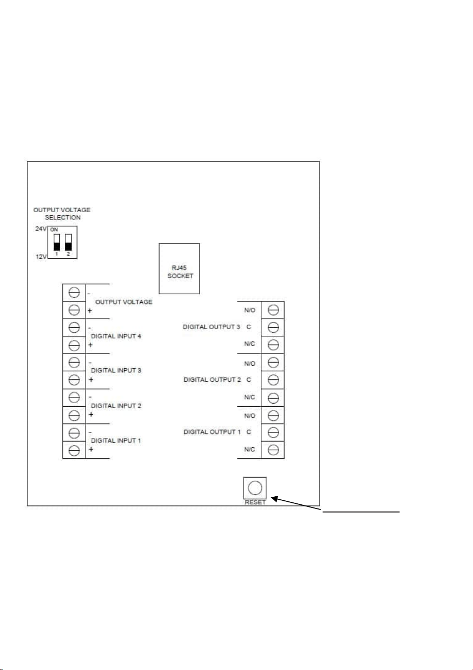
3.3. FACTORY RESET
1. Remove the service lid.
2. Disconnect the network cable.
3. Press and hold the reset button, while reconnecting the network cable.
4. Refit the service lid.
5. The unit will change IP address to default IP and login (see next page).
6. The unit will restart in the bootloader. Please refer to section 5.3.6.
Reset button

4. API
4.1. HTTP Requests
All HTTP requests are of the GET method. The HTTP requests are based on the
following layout:
http://<user>:<pass>@<ip-address>/<product>/<group>/<index>/<function>/<action>
<user> Saved username in the product
<pass> Saved password in the product
<ip-address> IP address of the product
4.1.1. IPA API Function List
Product
Group
Index
Function
Action
Description
ipa
Returns all status of the IPA
digital_inputs
Returns status of all digital
inputs
1
...
4
Returns status of selected
digital input
state
Returns state of selected
digital input
frequency
Returns frequency of
selected digital input
digital_outputs
Returns status of all digital
outputs
Returns status of selected
digital output
1
...
3
Returns state of selected
digital output
state
open
Sets selected digital output
to open
close
Sets selected digital output
to closed
HTTP request:
http://user:pass@<product-ip>/ipa/digital_inputs/1/state
Response:
“high”
HTTP request:
http://user:pass@<product-ip>/ipa/digital_inputs/4
Response:
{“state”: “low”, “frequency”: 0}
HTTP request:
http://user:pass@<product-ip>/ipa/digital_inputs
Response:
{
"1": {"state": "high", "frequency": 0},
"2": {"state":
"-",
"frequency": 34.5},
"3": {"state": "high", "frequency": 0},
"4": {"state": "low", "frequency": 0}
}
HTTP request:
http://user:pass@<product-ip>/ipa/analog_inputs/1/value
Response: 5432.1
HTTP request:
http://user:pass@<product-ip>/ipa/digital_outputs/1/state/close
Response: OK
4.1.2. Examples - Get Status Information
Each time a status is requested the IPA returns a JSON object. The JSON object is built up with the logic as described
in section 4.1.1.
Get state of a specific digital input with the following request.
Get status of a specific digital input with the following request.
Get status of all digital inputs with the following request.
Get the measured value from a specific analog input. The IPA returns a floating point number.
4.1.3. Examples - Action Commands
Close a specific digital output with the following request.

4.1.4. Example - Full Status
Get all status of the IPA with the following request.
HTTP request: http://user:pass@<product-ip>/ipa
Response:
{
"digital_inputs": {
"1": {
"state": "high",
"frequency": 0
},
"2": {
},
"digital_outputs": {
"1": {
},
"3": {
},
"4": {
}
"state": "-",
"frequency": 34.5
"state": "high",
"frequency": 0
"state": "low",
"frequency": 0
},
"2": {
},
"3": {
}
"state": "closed"
"state": "open"
"state": "open"
}

4.2. Modbus TCP
The internal Modbus TCP server/slave listens to TCP port 502 and is enabled by default. IPA
Modbus TCP uses a ‘big-endian’ representation for addresses and data items.
4.2.2. IPA Modbus TCP Register List
Hardware
function
Description
Modbus Function
(function code)
Address
Length
Digital input 1
Returns the status of IPA digital input
1
Read input
discretes (2)
0
1-bit
Digital input 2
Returns the status of IPA digital input
2
Read input
discretes (2)
1
1-bit
Digital input 3
Returns the status of IPA digital input
3
Read input
discretes (2)
2
1-bit
Digital input 4
Returns the status of IPA digital input
4
Read input
discretes (2)
3
1-bit
Digital input 1
Returns status of selected output
Read Coil (1)
0
1-bit
Set status of selected output
Write Single
Coil (5)
Digital input 2
Returns status of selected output
Read Coil (1)
1
1-bit
Set status of selected output
Write Single
Coil (5)
Digital input 3
Returns status of selected output
Read Coil (1)
2
1-bit
Set status of selected output
Write Single
Coil (5)
Digital input 1
frequency
Returns the frequency of the digital
input 1
Read Input
Registers (4)
0
32-bit
IEEE-745 float
Digital input 2
frequency
Returns the frequency of the digital
input 2
Read Input
Registers (4)
2
32-bit
IEEE-745 float
Digital input 3
frequency
Returns the frequency of the digital
input 3
Read Input
Registers (4)
4
32-bit
IEEE-745 float
Digital input 4
frequency
Returns the frequency of the digital
input 4
Read Input
Registers (4)
6
32-bit
IEEE-745 float
5. USER INTERFACE
All settings are made through the web based user interface. This means there are no limits
in hardware or software for using the systems, all that is needed is a modern web browser.
The instructions for the user interface described below are valid for firmware 1.1..
5.1. Factory Default Settings
When using the system for the first time, or if a factory reset has been made, the
following settings are used.
Product IP number 192.168.0.10
Subnet mask 255.255.255.0
Default router 192.168.0.1
Username admin
Password admin
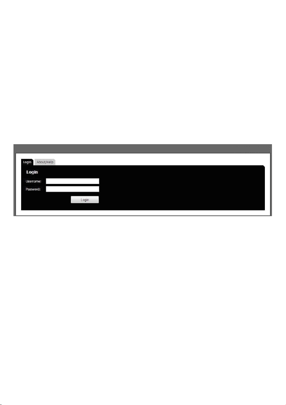
5.2. Login
1. Open a web browser
2. In the address field, type in the selected unit IP-address.
3. The user interface login page is shown.
4. Login with your username and password.
5.3. Installation and Configuration
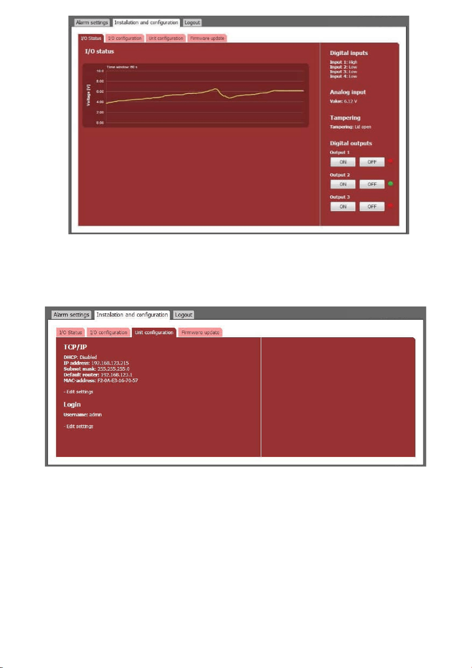
5.3.1. I/O Status
1. Open the Installation and configuration tab
2. The default sub-tab is the I/O Status window.
3. The diagram displays the analog input signal during the last 60 seconds.
4. To the right is a list with current digital inputs status, analog input value, tampering sensor status, digital
outputs status (green indicates on), and buttons to manually control the digital outputs.
5.3.2. Unit Configuration
1. Open the sub-tab in the installation and configuration window.
2. Current settings are shown.
3. To change TCP/IP settings, press Edit settings. Input fields appear to the right.
4. Enter desired settings and press the save button. Remember to reload the page with the new IP address if
changed.
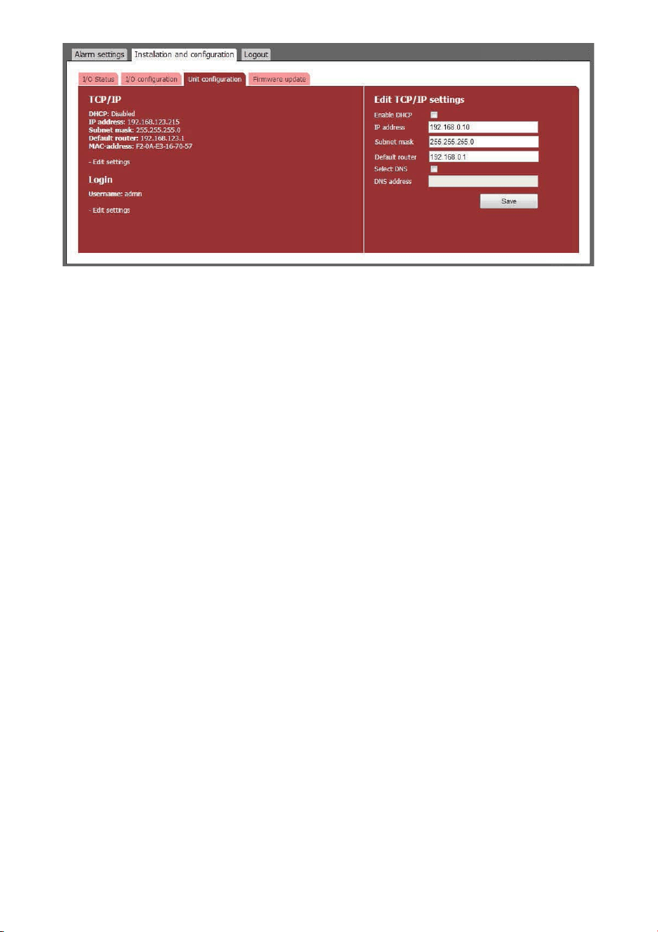
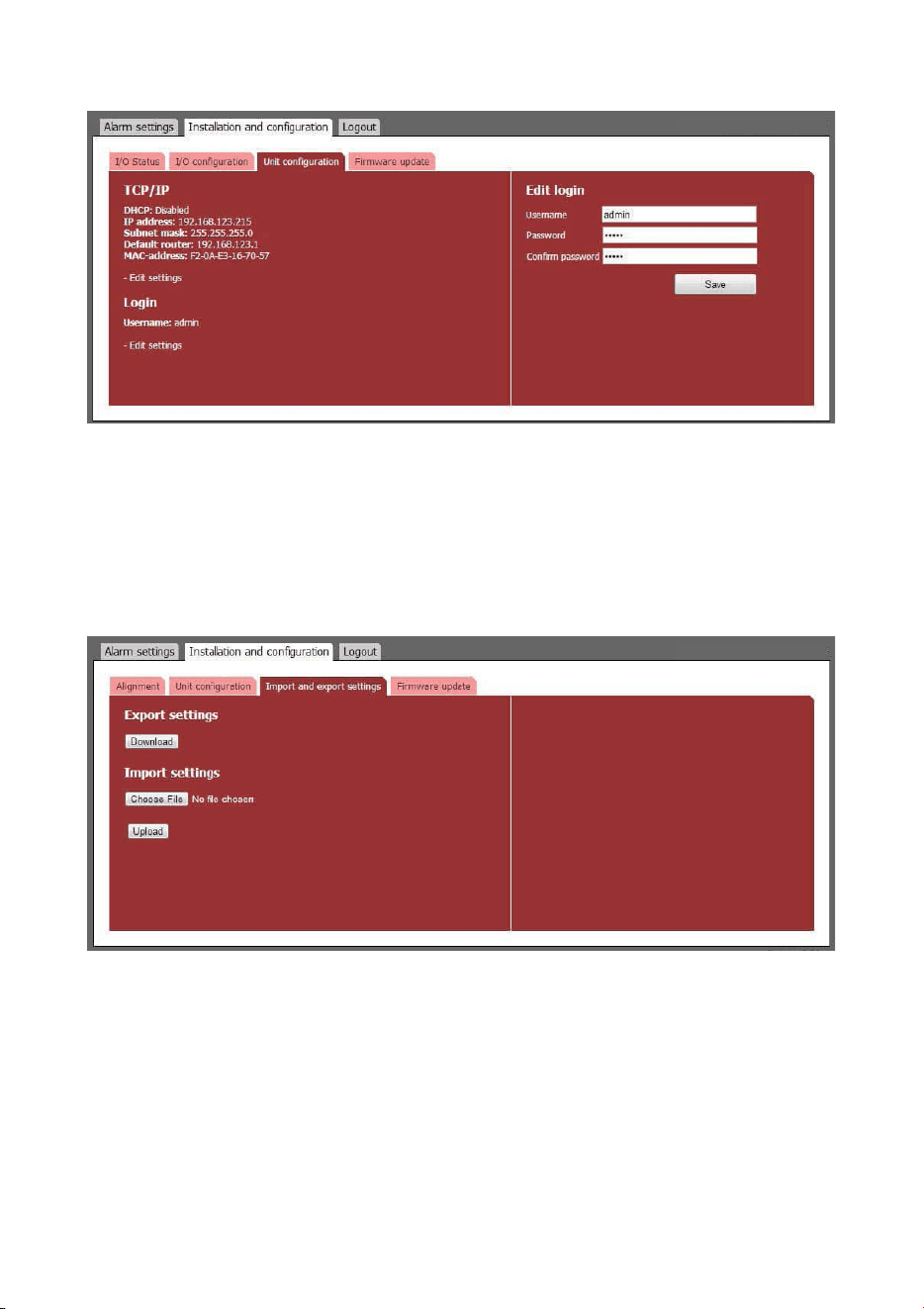
5. To change Login settings, press Edit settings. Input fields appear to the right.
6. Enter a new username and password.
7. Press the save button to confirm.
5.3.3. Import and Export Settings
Alarm settings and I/O configuration can be exported as a file for backup purposes and to copy the settings to other
units. IP address and Login settings are not included in this file.
1. Open the Import and export settings sub-tab in the Installation and configuration tab.
2. Export all current alarm settings and I/O configuration by pressing the Download button. Pay attention to
the file location on your hard drive. The file name is individual for each unit as it includes the unit MAC-
address.
3. To import a setting file, press Choose File button and navigate to the location of your setting file on your hard
drive.
4. When the file is selected it is possible to import it with the Upload button. Pay attention to the status message
next to the button. Importing a setting file will overwrite all current settings.
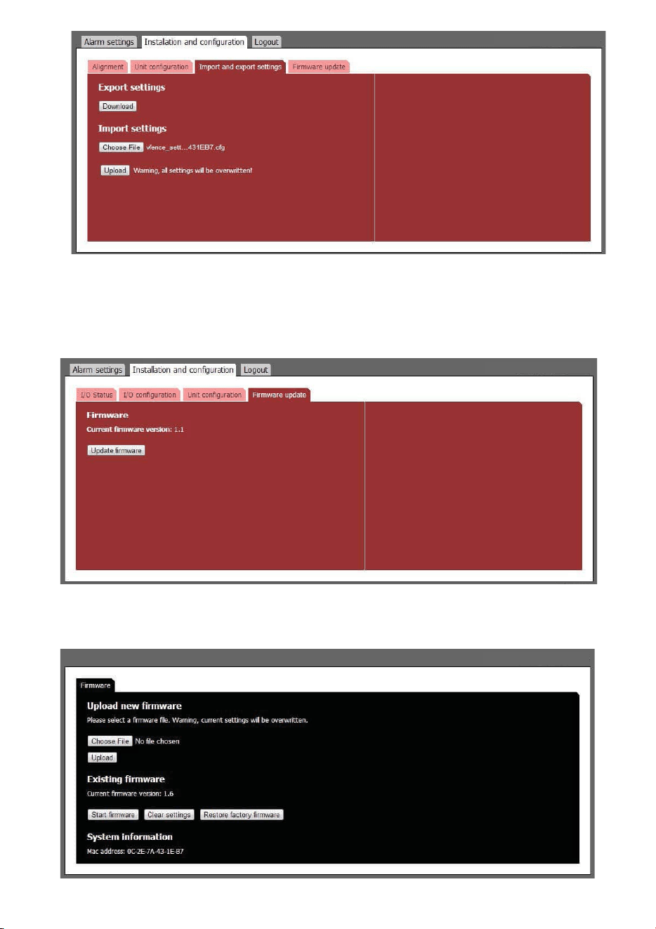
5.3.4. Firmware Update
The IPA firmware can be updated to add new functions or resolve software issues.
1. Open the Firmware update sub-tab in the Installation and configuration tab. Current firmware version is displayed.
2. Press the Update firmware button to stop the firmware and enter the system bootloader.
3. In the bootloader, you have the option to upload a new firmware, clear all
settings (restore factory settings) and restore factory firmware.
4. To restore factory settings, press Clear settings button. Press Start firmware to start the IPA firmware again.
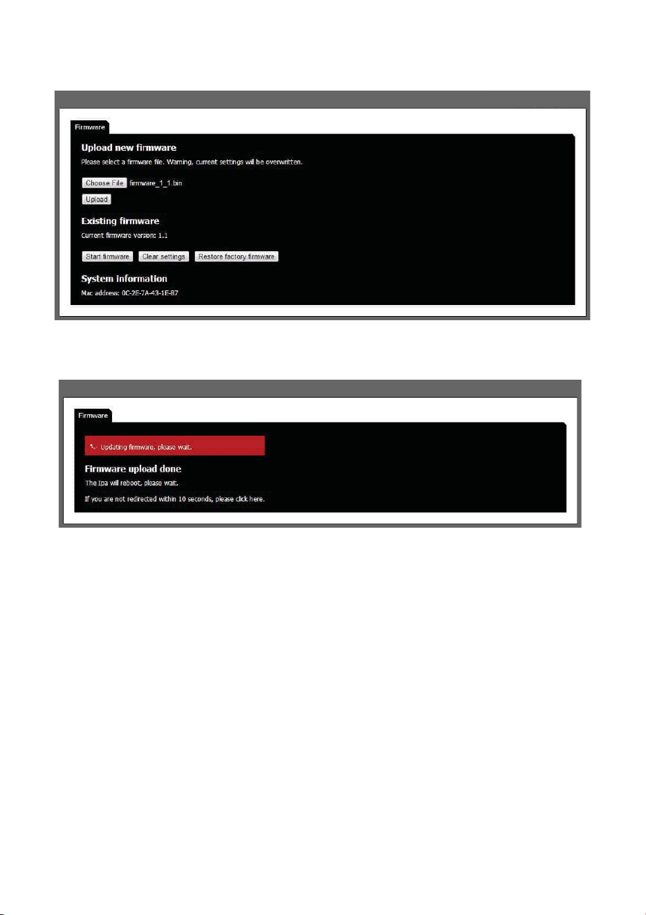
5. To upload a new firmware, press Choose File button and navigate to the location of the firmware file on your
hard drive. When a file is selected the file name is displayed next to the button. Uploading a new firmware
will erase all alarm and configuration settings.
6. Press Upload button. The firmware file will be uploaded to the vFence F-501. When the file is uploaded, the
unit will replace the firmware and then reboot the system with the new firmware.
7. After the reboot the firmware settings page will be shown again.
8. Press Start firmware button to restart the IPA with the new firmware.
5.3.5. Restart After Hardware Reset
1. The unit will start in bootloader.
2. If there is any issue with the firmware, please restore factory firmware by
pressing Restore factory firmware button.
3. Press the Start firmware button to restart the unit with the factory default IP address and login.
5.4. ALARM SETTINGS
All alarm settings are made in the Alarm inputs sub-tab in the Alarm settings main tab. The IPA works on the
principle “Alarm - Action”. This means that alarms are created based on all types of input signals. For each alarm
it is possible to create one or more actions. The actions can be network alarm message or to trigger a relay.
5.4.1. Digital Input Alarms
1. Go to the Alarm inputs sub-tab in the Alarm settings main tab.
2. Press + Add alarm to create an event. Input fields appear on the right.
3. Enter a unique alarm name.
4. From the Input dropdown menu, choose the digital input that corresponds to the electrical connection on the IPA.
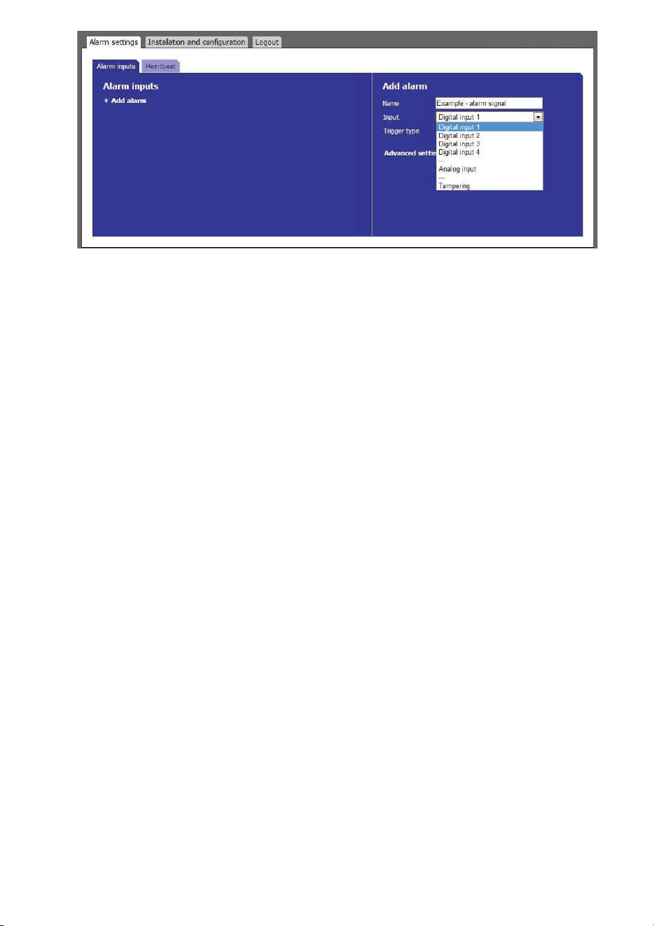
5. Choose Trigger type from the dropdown menu.
High The alarm is enabled when the input voltage is "high" according to section 1.2.
Low The alarm is enabled when the input voltage is "low" according to section 1.2.
Rising edge The alarm is enabled when the input voltage is changed from "low" to "high" according to
section 1.2.
Falling edge The alarm is enabled when the input voltage is changed from "high" to "low" according to
section 1.2.
Pulse frequency The IPA measures the frequency at which the input changes between "low" and "high"
according to section 1.2.The alarm is enabled if the frequency exceeds or falls below desired
limits.
Below is separate descriptions on how to proceed depending on trigger
type. High / Low / Rising edge / Falling edge alarm
6. No extra settings are needed for the alarm. Go to step 8.
Pulse frequency
7. Set Upper limit for the pulse frequency. Maximum value is 2500 Hz.
8. Set Lower limit for the pulse frequency. Minimum value is 0.2 Hz.
9. This step describes advanced settings. These optional settings can be used to change the alarm behavior
depending on the application. Different advanced settings are shown depending on trigger type.
Alarm delay Alarm delay specifies the time for which the alarm conditions must be continuously fulfilled
before the alarm is enabled. Default value is 0 seconds, maximum is 120 seconds.
Timeout Timeout specifies the time before the alarm is disabled after the alarm conditions are no
longer met. Default value is 0 seconds,maximum is 120 seconds.
Hysteresis Hysteresis is used to avoid unstable alarm conditions when the pulse frequency is close to
the limit values. The hysteresis specifies the reset value for the upper and lower limits. If no
value is set or if the value is set to 0, the default hysteresis value of 1% will be used.
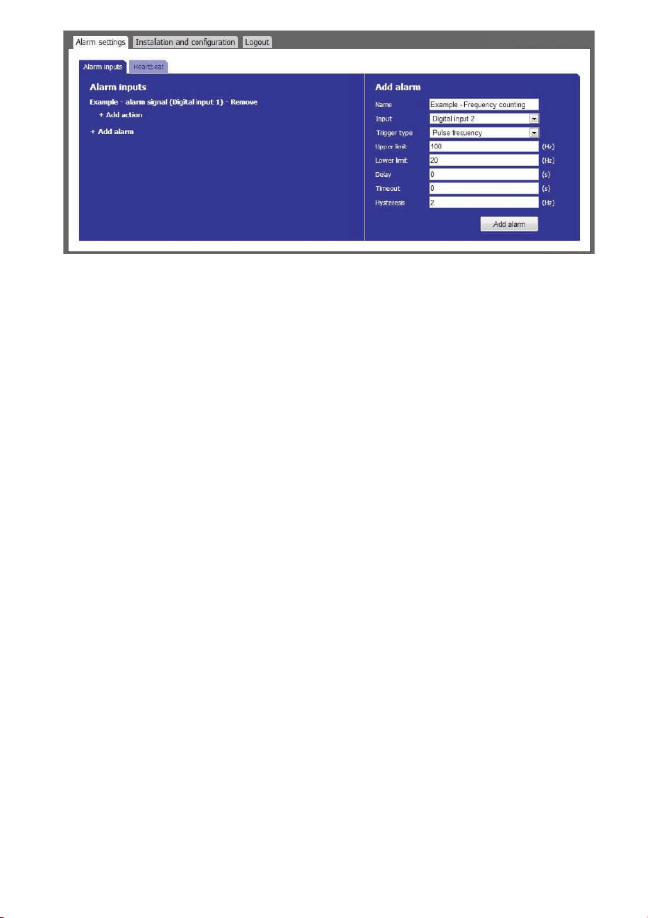
10. Press the Add alarm button to save the alarm event.
11. Repeat step 2 to 9 for all digital input alarms.
1. Press the Add alarm button to save the alarm event.
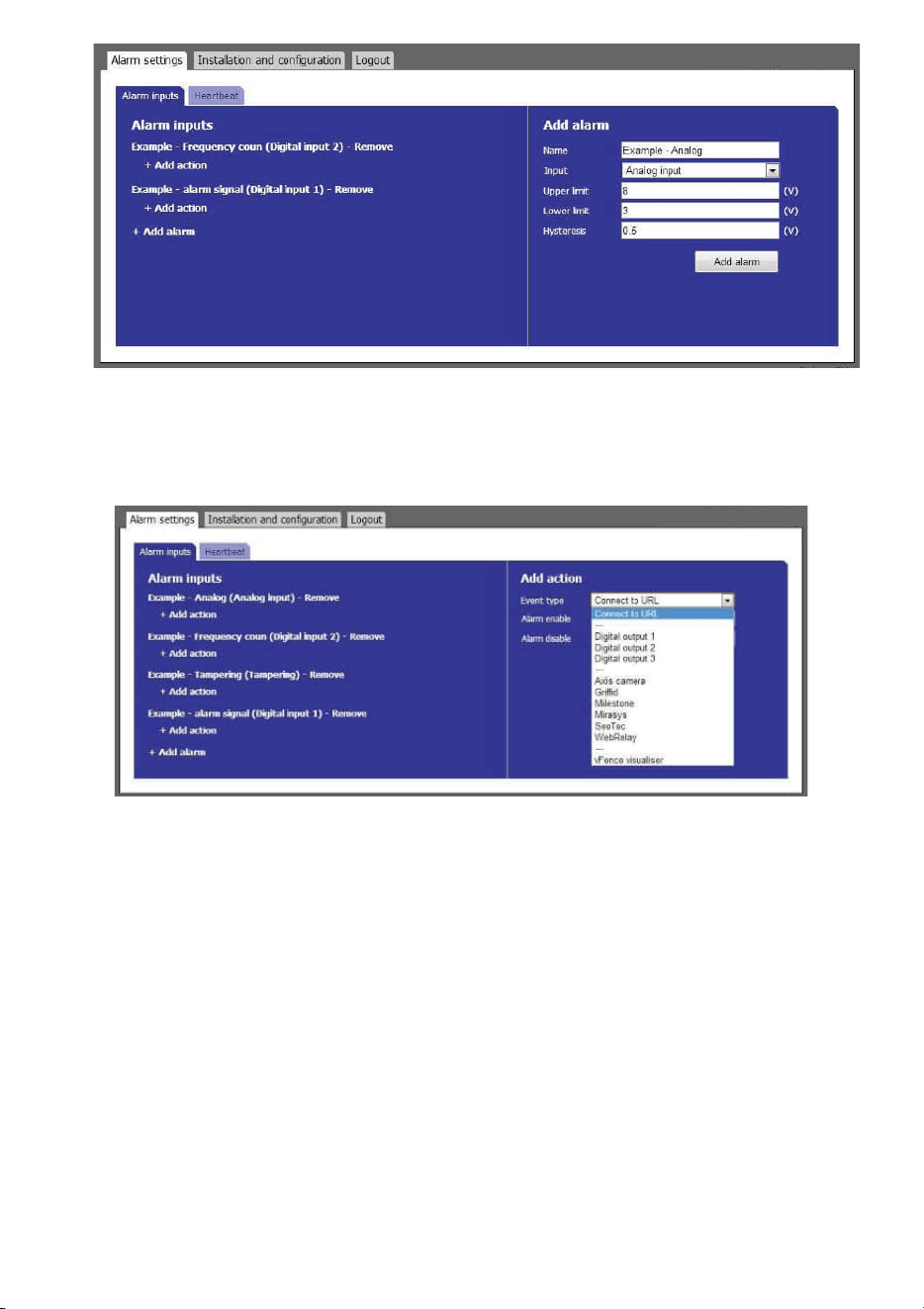
5.4.2. Create Alarm Actions
1. Press + Add action under the desired alarm. Input fields appear to the right.
2. Choose action type from the Event type dropdown menu.
Connect to URL Connect to URL is used to create any type of network alarm. This allows to have one URL
request at alarm enable and one URL request at alarm disable.
Digital output 1-3 This turns the selected digital output on at alarm enable and turns it off at alarm disable.
Partner list The products listed have a built-in wizard in the IPA that creates the specific URL request
needed for the application. This list is continuously expanding. Please refer to separate
documents regarding integration of these products.
vFence Visualiser This wizard creates an URL request used in combination with GJD software vFence Visualiser.
3. Fill in required data fields for the selected Event type.
4. Press the Add action button to save the action.
5. Press Test next to the action for an alarm to test the action.
6. Repeat step 1-5 for each alarm.
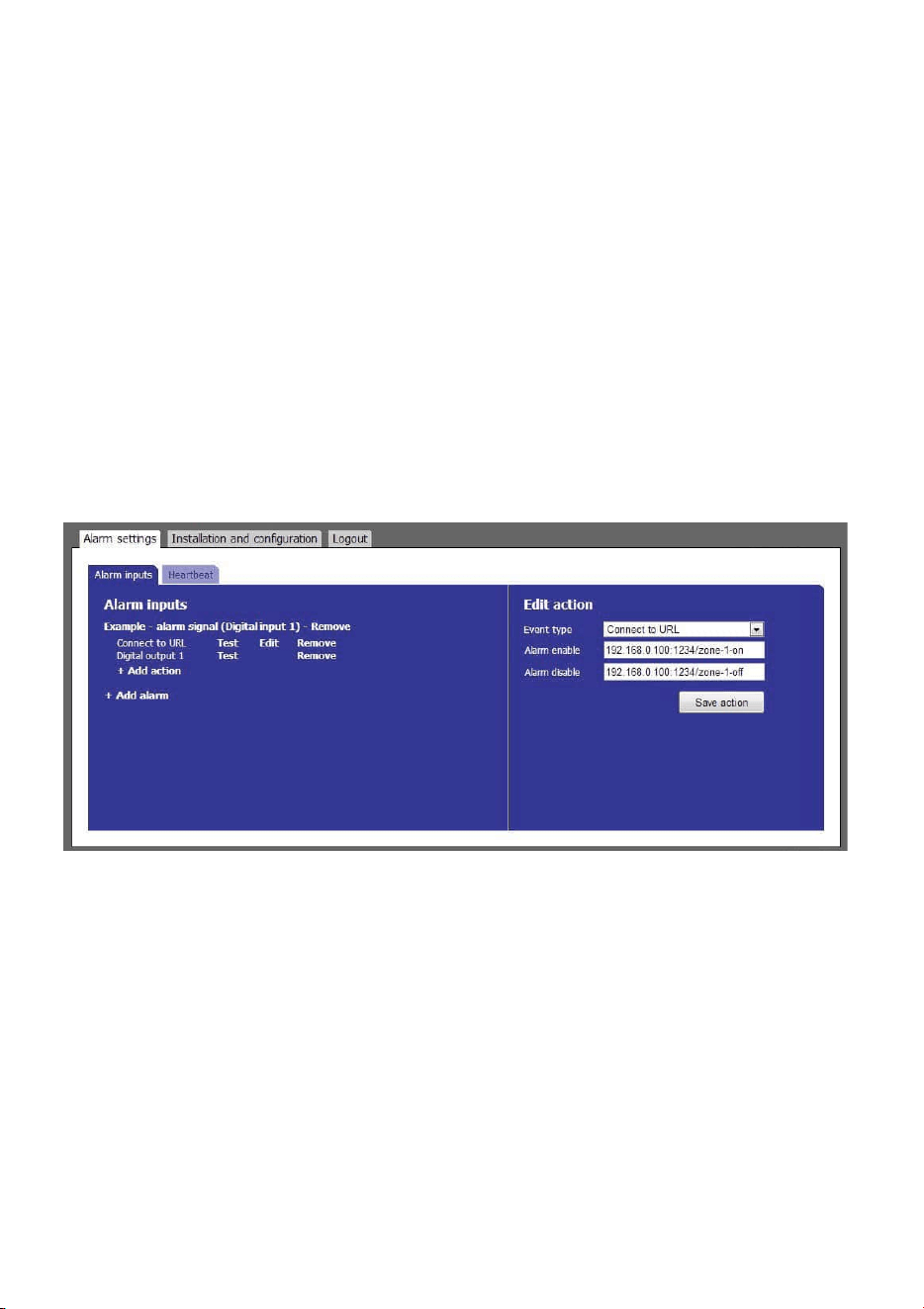
5.4.3. Edit and Remove Alarms
1. Edit an alarm by pressing the alarm name. The alarm settings appear to the right.
2. When the alarm settings are changed, press the Save alarm button to save the changes. Pressing any other
link will discard all changes.
3. Remove an alarm by pressing the Remove link next to the alarm name. Removing an alarm cannot be undone.
5.4.4. Edit and Remove Actions
1. Edit an URL request action by pressing Edit next to the action. Digital output actions cannot be edited. The
input fields appear to the right.
2. When the action settings are changed, press the Save action button to save the changes. Pressing any other
link will discard all changes.
3. Remove an action by pressing the Remove link next to the action name. Removing an action cannot be undone.
5.4.5. Heartbeat
The heartbeat indicates that the IPA is alive and is working. It is used to detect cable break and product malfunction by
periodically send a short message to the server. Server software to receive heartbeats is necessary.
1. In the Alarm settings tab, open the Heartbeat sub tab
2. Press “Edit settings”. Input fields appear on the right.
3. Enter desired URL for heartbeat, for example the VMS server.
4. Enter desired time interval between heartbeats.
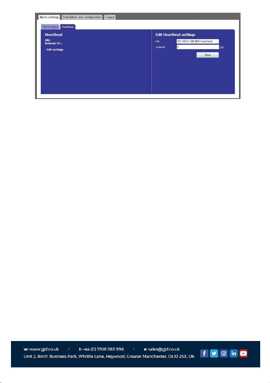
5. Press the save button to confirm the settings.
5.5. LOGOUT
1. Press the "Logout" tab in the top menu.
2. You will automatically be logged out if anybody logs in from another computer.