
Video Intercom Main Staon
Operaon Guide

Legal Informaon
©2020 Hangzhou Hikvision Digital Technology Co., Ltd. All rights reserved.
About this Manual
The Manual includes instrucons for using and managing the Product. Pictures, charts, images and
all other informaon hereinaer are for descripon and explanaon only. The informaon
contained in the Manual is subject to change, without noce, due to rmware updates or other
reasons. Please nd the latest version of this Manual at the Hikvision website ( hps://
www.hikvision.com/ ).
Please use this Manual with the guidance and assistance of professionals trained in
supporng the
Product.
Trademarks
and other Hikvision's trademarks and logos are the properes of
Hikvision in various jurisdicons.
Other trademarks and logos menoned are the properes of their respecve owners.
Disclaimer
TO THE MAXIMUM EXTENT PERMITTED BY APPLICABLE LAW, THIS MANUAL AND THE PRODUCT
DESCRIBED, WITH ITS HARDWARE, SOFTWARE AND FIRMWARE, ARE PROVIDED “AS IS” AND “WITH
ALL FAULTS AND ERRORS”. HIKVISION MAKES NO WARRANTIES, EXPRESS OR IMPLIED, INCLUDING
WITHOUT LIMITATION, MERCHANTABILITY, SATISFACTORY QUALITY, OR FITNESS FOR A PARTICULAR
PURPOSE. THE USE OF THE PRODUCT BY YOU IS AT YOUR OWN RISK. IN NO EVENT WILL HIKVISION
BE LIABLE TO YOU FOR ANY SPECIAL, CONSEQUENTIAL, INCIDENTAL, OR INDIRECT DAMAGES,
INCLUDING, AMONG OTHERS, DAMAGES FOR LOSS OF BUSINESS PROFITS, BUSINESS
INTERRUPTION, OR LOSS OF DATA, CORRUPTION OF SYSTEMS, OR LOSS OF DOCUMENTATION,
WHETHER BASED ON BREACH OF CONTRACT, TORT (INCLUDING NEGLIGENCE), PRODUCT LIABILITY,
OR OTHERWISE, IN CONNECTION WITH THE USE OF THE PRODUCT, EVEN IF HIKVISION HAS BEEN
ADVISED OF THE POSSIBILITY OF SUCH DAMAGES OR LOSS.
YOU ACKNOWLEDGE THAT THE NATURE OF INTERNET PROVIDES FOR INHERENT SECURITY RISKS,
AND HIKVISION SHALL NOT TAKE ANY RESPONSIBILITIES FOR ABNORMAL OPERATION, PRIVACY
LEAKAGE OR OTHER DAMAGES RESULTING FROM CYBER-ATTACK, HACKER ATTACK, VIRUS
INSPECTION, OR OTHER INTERNET SECURITY RISKS; HOWEVER, HIKVISION WILL PROVIDE TIMELY
TECHNICAL SUPPORT IF REQUIRED.
YOU AGREE TO USE THIS PRODUCT IN COMPLIANCE WITH ALL APPLICABLE LAWS, AND YOU ARE
SOLELY RESPONSIBLE FOR ENSURING THAT YOUR USE CONFORMS TO THE APPLICABLE LAW.
ESPECIALLY, YOU ARE RESPONSIBLE, FOR USING THIS PRODUCT IN A MANNER THAT DOES NOT
INFRINGE ON THE RIGHTS OF THIRD PARTIES, INCLUDING WITHOUT LIMITATION, RIGHTS OF
PUBLICITY, INTELLECTUAL PROPERTY RIGHTS, OR DATA PROTECTION AND OTHER PRIVACY RIGHTS.
YOU SHALL NOT USE THIS PRODUCT FOR ANY PROHIBITED END-USES, INCLUDING THE
Video Intercom Main Staon Operaon Guide
i

DEVELOPMENT OR PRODUCTION OF WEAPONS OF MASS DESTRUCTION, THE DEVELOPMENT OR
PRODUCTION OF CHEMICAL OR BIOLOGICAL WEAPONS, ANY ACTIVITIES IN THE CONTEXT RELATED
TO ANY NUCLEAR EXPLOSIVE OR UNSAFE NUCLEAR FUEL-CYCLE, OR IN SUPPORT OF HUMAN
RIGHTS ABUSES.
IN THE EVENT OF ANY CONFLICTS BETWEEN THIS MANUAL AND THE APPLICABLE LAW, THE LATER
PREVAILS.
Video Intercom Main Staon Operaon Guide
ii
Symbol Convenons
The symbols that may be found in this document are dened as follows.
Symbol Descripon
Danger
Indicates a hazardous situaon which, if not avoided, will or could
result in death or serious injury.
Cauon
Indicates a potenally hazardous situaon which, if not avoided, could
result in equipment damage, data loss, performance degradaon, or
unexpected results.
Note
Provides addional informaon to emphasize or supplement
important points of the main text.
Video Intercom Main Staon Operaon Guide
iii

Regulatory Informaon
FCC Informaon
Please take aenon that changes or modicaon not expressly approved by the party responsible
for compliance could void the user's authority to operate the equipment.
FCC compliance: This equipment has been tested and found to comply with the limits for a Class B
digital device, pursuant to part 15 of the FCC Rules. These limits are designed to provide
reasonable
protecon against harmful interference in a residenal installaon. This equipment
generates, uses and can radiate radio frequency energy and, if not installed and used in accordance
with the
instrucons, may cause harmful interference to radio communicaons. However, there is
no guarantee that interference will not occur in a parcular installaon. If this equipment does
cause harmful interference to radio or television
recepon, which can be determined by turning
the equipment o and on, the user is encouraged to try to correct the interference by one or more
of the following measures:
●
Reorient or relocate the receiving antenna.
●
Increase the separaon between the equipment and receiver.
●
Connect the equipment into an outlet on a circuit
dierent from that to which the receiver is
connected.
●
Consult the dealer or an experienced radio/TV technician for help.
FCC
Condions
This device complies with part 15 of the FCC Rules. Operaon is subject to the following two
condions:
●
This device may not cause harmful interference.
●
This device must accept any interference received, including interference that may cause
undesired
operaon.
EU Conformity Statement
This product and - if applicable - the supplied accessories too are marked
with "CE" and comply therefore with the applicable harmonized European
standards listed under the EMC Direcve 2014/30/EU, LVD Direcve 2014/
35/EU, the RoHS
Direcve 2011/65/EU.
2012/19/EU (WEEE direcve): Products marked with this symbol cannot be
disposed of as unsorted municipal waste in the European Union. For
proper recycling, return this product to your local supplier upon the
Video Intercom Main Staon Operaon Guide
iv

purchase of equivalent new equipment, or dispose of it at designated
collecon points. For more informaon see: hp://www.recyclethis.info .
2006/66/EC (baery direcve): This product contains a baery that cannot
be disposed of as unsorted municipal waste in the European Union. See
the product documentaon for specic baery informaon. The baery is
marked with this symbol, which may include
leering to indicate cadmium
(Cd), lead (Pb), or mercury (Hg). For proper recycling, return the
baery to
your supplier or to a designated
collecon point. For more informaon
see: hp://www.recyclethis.info .
Industry Canada ICES-003 Compliance
This device meets the CAN ICES-3 (B)/NMB-3(B) standards requirements.
Video Intercom Main Staon Operaon Guide
v

Contents
Chapter 1 Appearance ................................................................................................................ 1
Chapter 2 Terminal Descripon .................................................................................................. 4
Chapter 3 Installaon ................................................................................................................. 6
3.1 Table Bracket(Oponal) ......................................................................................................... 6
3.2 Accessory Installaon(Oponal) ............................................................................................ 6
3.2.1 Install Speaker ............................................................................................................... 6
3.2.2 Install Goose Neck Microphone .................................................................................... 8
3.3 Wall Mounng ....................................................................................................................... 9
3.4 Table
Mounng .................................................................................................................... 10
Chapter 4 Local Operaon ........................................................................................................ 12
4.1 Call Sengs .......................................................................................................................... 12
4.1.1 Call Resident ............................................................................................................... 12
4.1.2 Receive Call ................................................................................................................. 13
4.1.3 View Call Logs ............................................................................................................. 13
4.2 Live View .............................................................................................................................. 14
4.3 The Third-Party App
Sengs ............................................................................................... 14
4.3.1 Install the App ............................................................................................................. 14
4.3.2 Uninstall the App ........................................................................................................ 15
4.4
Informaon Management .................................................................................................... 16
Chapter 5 Remote Operaon via the Client Soware ................................................................ 17
5.1 View Live Video of Door
Staon and Outer Door Staon .................................................... 17
5.2 View Call Logs ...................................................................................................................... 17
5.3 Release Noce ..................................................................................................................... 18
5.4 Search Video Intercom
Informaon ..................................................................................... 21
5.4.1 Search Call Logs ........................................................................................................... 21
5.4.2 Search Noce .............................................................................................................. 23
Video Intercom Main Staon Operaon Guide
vi

Chapter 1 Appearance
Front Panel
Figure 1-1 Front Panel
Table 1-1
Descripon
No. Descripon No. Descripon
1 Phone 7 Camera
2 Phone Indicator(Reserved) 8 Screen
3 Power Indicator 9 Call/Hang Up Buon
4 Alarm Indicator 10 Unlock Buon
5 Informaon Indicator 11 Speaker Buon
6 Microphone
Video Intercom Main Staon Operaon Guide
1
Note
You can hold the unlock buon to unlock lock 1, and press the unlock buon to unlock lock 2.
Top Panel and Rear Panel
Figure 1-2 Top Panel and Rear Panel
Table 1-2
Descripon
No. Descripon No. Descripon
1 Goose Neck Microphone Port 5 USB Interface
2 SD Card Slot 6 Power Interface
3 Earphone Interface 7 Terminals (Reserved)
4 HDMI 8 Network Interface
Video Intercom Main Staon Operaon Guide
2
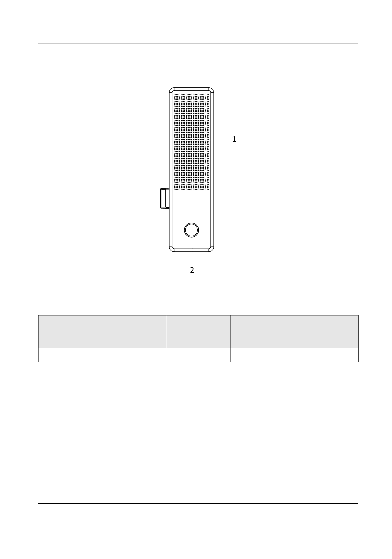
Speaker(Oponal)
Figure 1-3 Speaker
Table 1-3
Descripon
N
o
.
Descripon No. Descripon
1Speaker 2 Fingerprint Module
Video Intercom Main Staon Operaon Guide
3
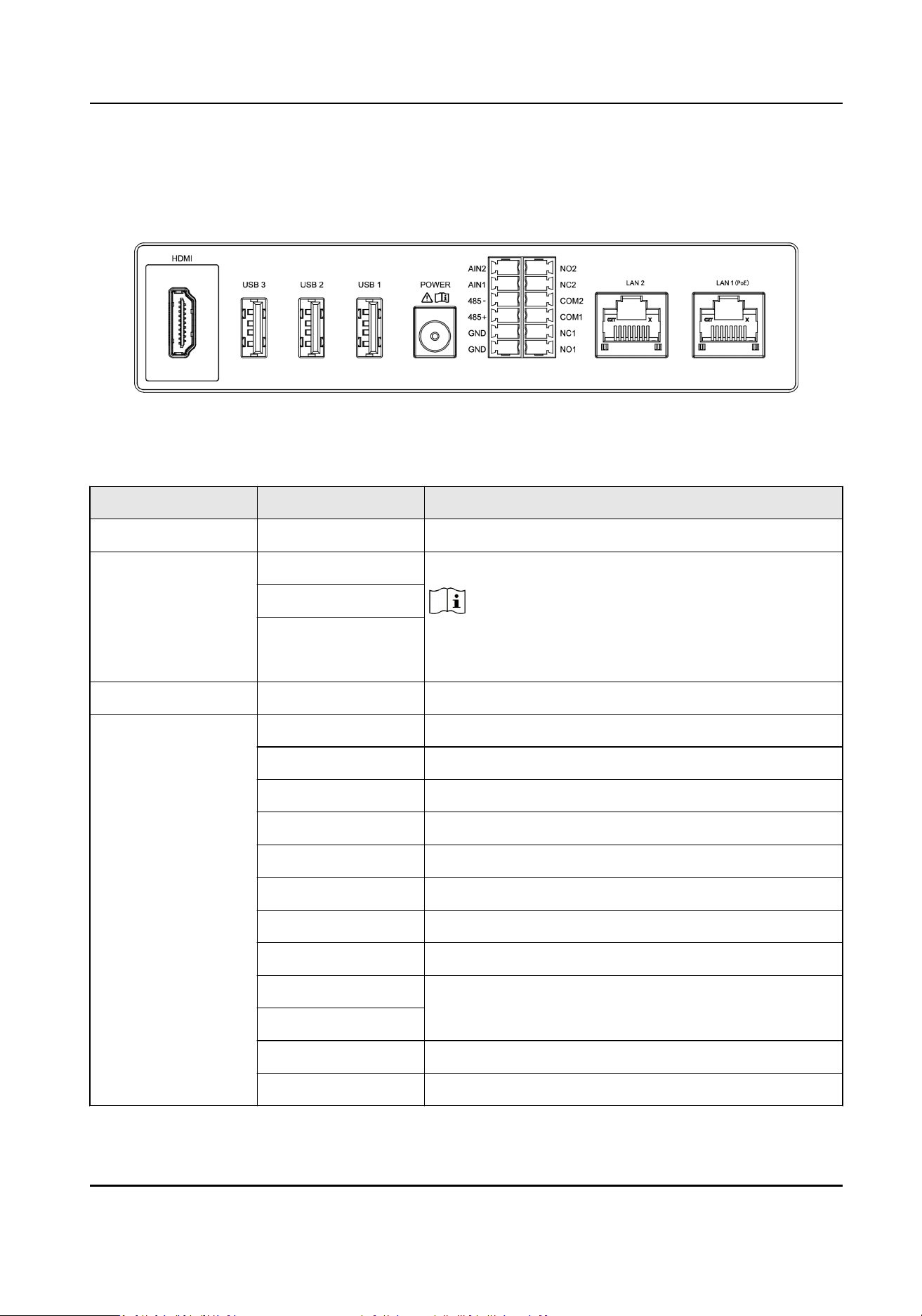
Chapter 2 Terminal Descripon
Figure 2-1 Terminal Descripon
Table 2-1 Terminal Descripon
Name Interface Descripon
Video Interface HDMI HDMI Signal Output
USB Interface USB 1 USB Interface
Note
USB3 is used to debugging only. It cannot connect to
USB ash drive.
USB 2
USB 3
Power Interface POWER 12 VDC Power Input
Terminal (Reserved) NO1 Alarm Output 1(NO)
NC1 Alarm Output 1(NC)
COM1 Common Interface
NO2 Alarm Output 2(NO)
NC2 Alarm Output 2(NC)
COM2 Common Interface
AIN1 Alarm Input 1
AIN2 Alarm Input 2
485+ RS-485 Communicaon Interfaces
485-
GND Grounding
GND Grounding
Video Intercom Main Staon Operaon Guide
4

Name Interface Descripon
Network Interface LAN1(PoE) Network Interface (Support PoE)
LAN2 Network Interface (Reserved)
Video Intercom Main Staon Operaon Guide
5
Chapter 3 Installaon
●
Make sure the device in the package is in good condion and all the assembly parts are included.
●
The power supply the door staon support is 12 VDC. Please make sure your power supply
matches your door staon.
●
Make sure all the related equipment is
power-o during the installaon.
●
Check the product specicaon for the installaon environment.
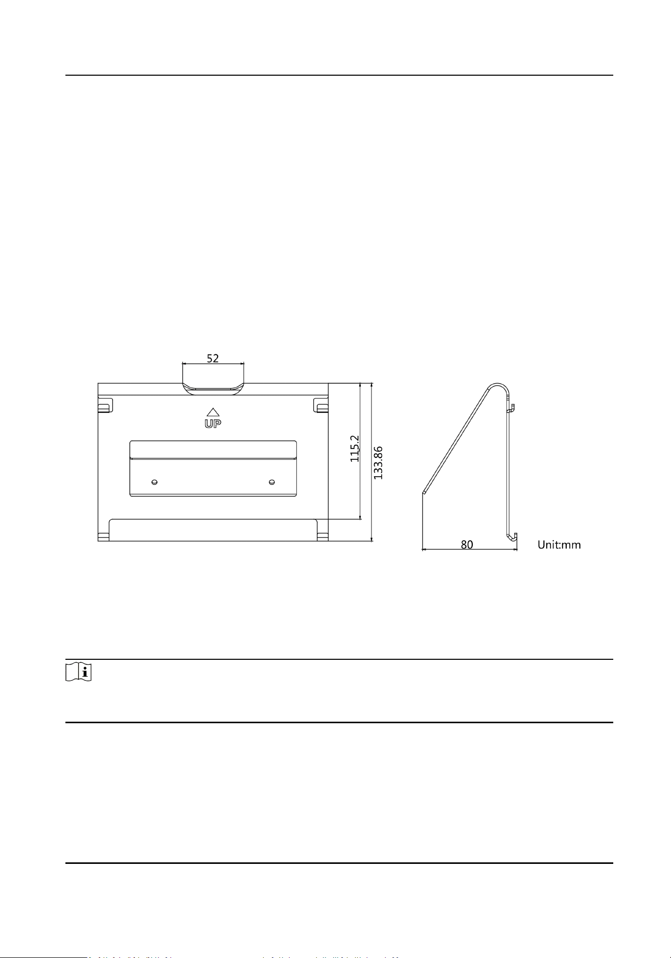
3.1 Table Bracket(Oponal)
The device supports table mounng and wall mounng. The dimensions of the table
bracket(oponal) is shown as below.
Figure 3-1 Table Bracket
3.2 Accessory
Installaon(Oponal)
Before installing the device on the wall or on the table, you should install the accessories rst.
Note
Ask our technique supports and sales and purchase mounng plate, speaker and goose neck
microphone.
3.2.1 Install Speaker
Steps
1.
Loose 2 screws on the rear panel of the device.
Video Intercom Main Staon Operaon Guide
6
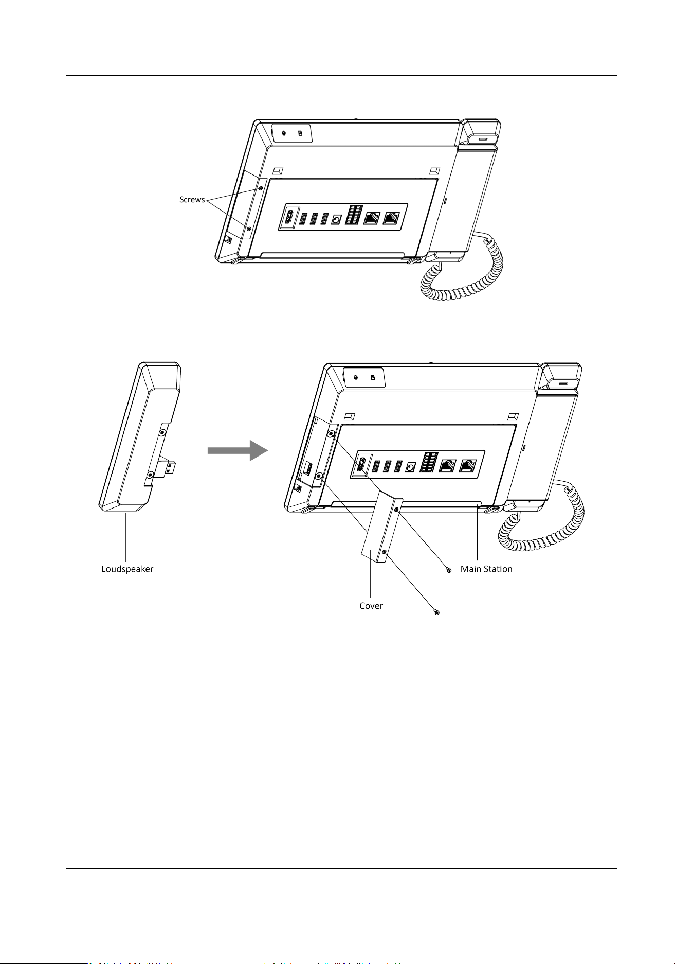
Figure 3-2 Loose the screws
2.
Remove the cover from the device and install the speaker to the main staon.
Figure 3-3 Install the Speaker
3.
Use 4 screws to secure the speaker to the main staon with the cover.
Video Intercom Main Staon Operaon Guide
7
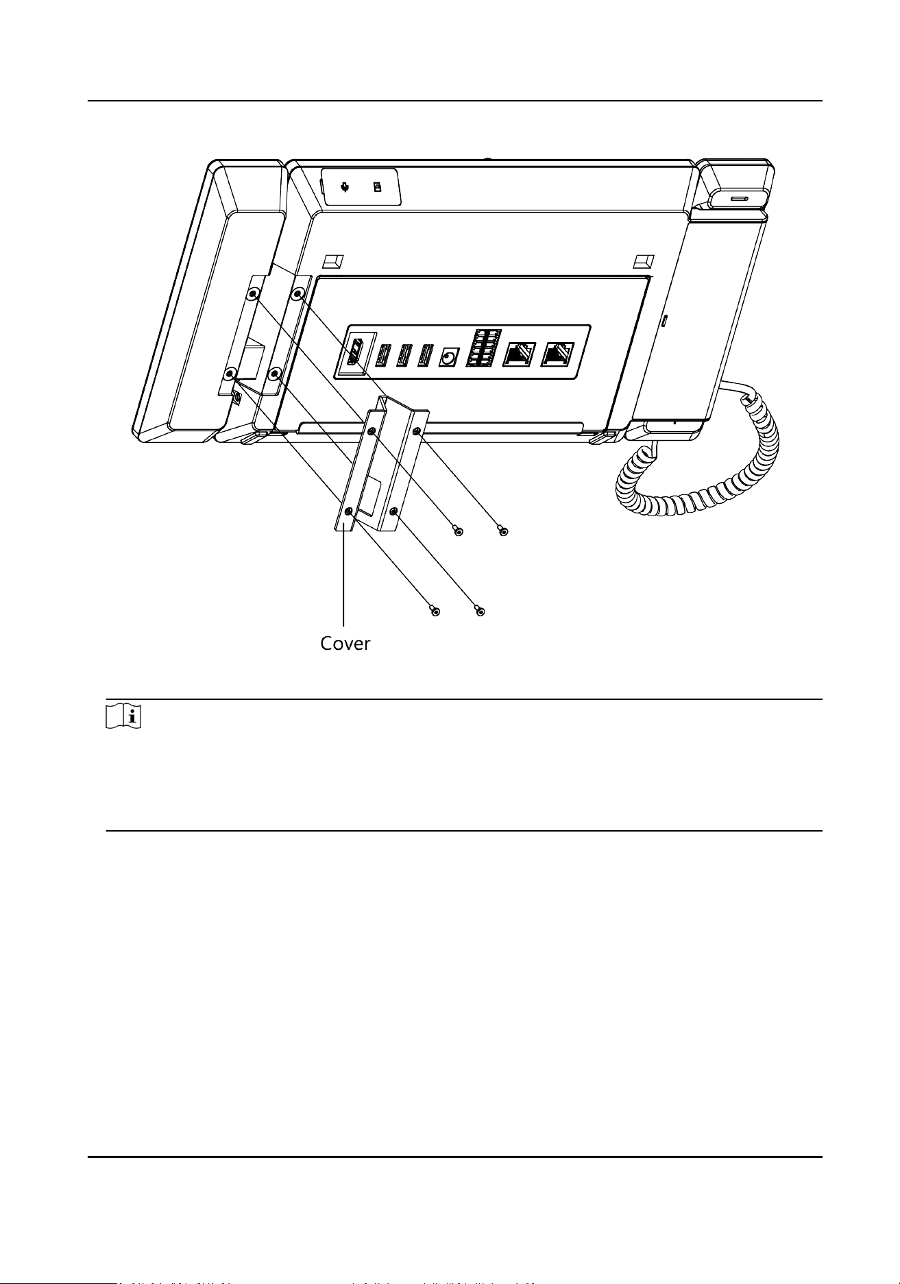
Figure 3-4 Secure the Speaker
Note
●
The speaker and earphone can not be used at the same me. If you want to use the
earphone, you should remove the speaker.
●
When using earphones, the small size of the earphone plug should be selected. The size of the
plug should be smaller than 7 mm.
3.2.2 Install Goose Neck Microphone
If you want to use the goose neck microphone to create two-way audio communicaon.
Steps
1.
Remove the cover of the device on the top panel.
2.
Insert the goose neck microphone to the interface.
Video Intercom Main Staon Operaon Guide
8
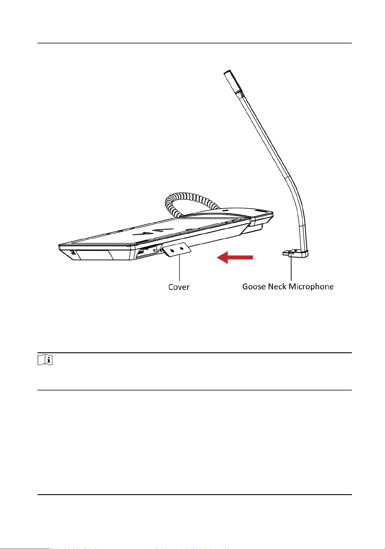
Figure 3-5 Install the Goose Neck Microphone
3.3 Wall
Mounng
Before You Start
Note
●
Tools that you need to prepare for installaon: Drill (6).
●
Make sure all the related equipment is power-o during the installaon.
Steps
1.
Place the table bracket on the wall. Mark the screw holes'
posion with a marker, and take out
the the table bracket. Drill 4 holes according to the marks on the wall, and insert the expansion
sleeves into the screw holes.
2.
Secure the table bracket on the wall with 4 screws.
3.
Hook the device to the table bracket
ghtly by inserng the hooks into the slots on the rear
panel of the device,during which the lock catch will be locked automacally.
Video Intercom Main Staon Operaon Guide
9
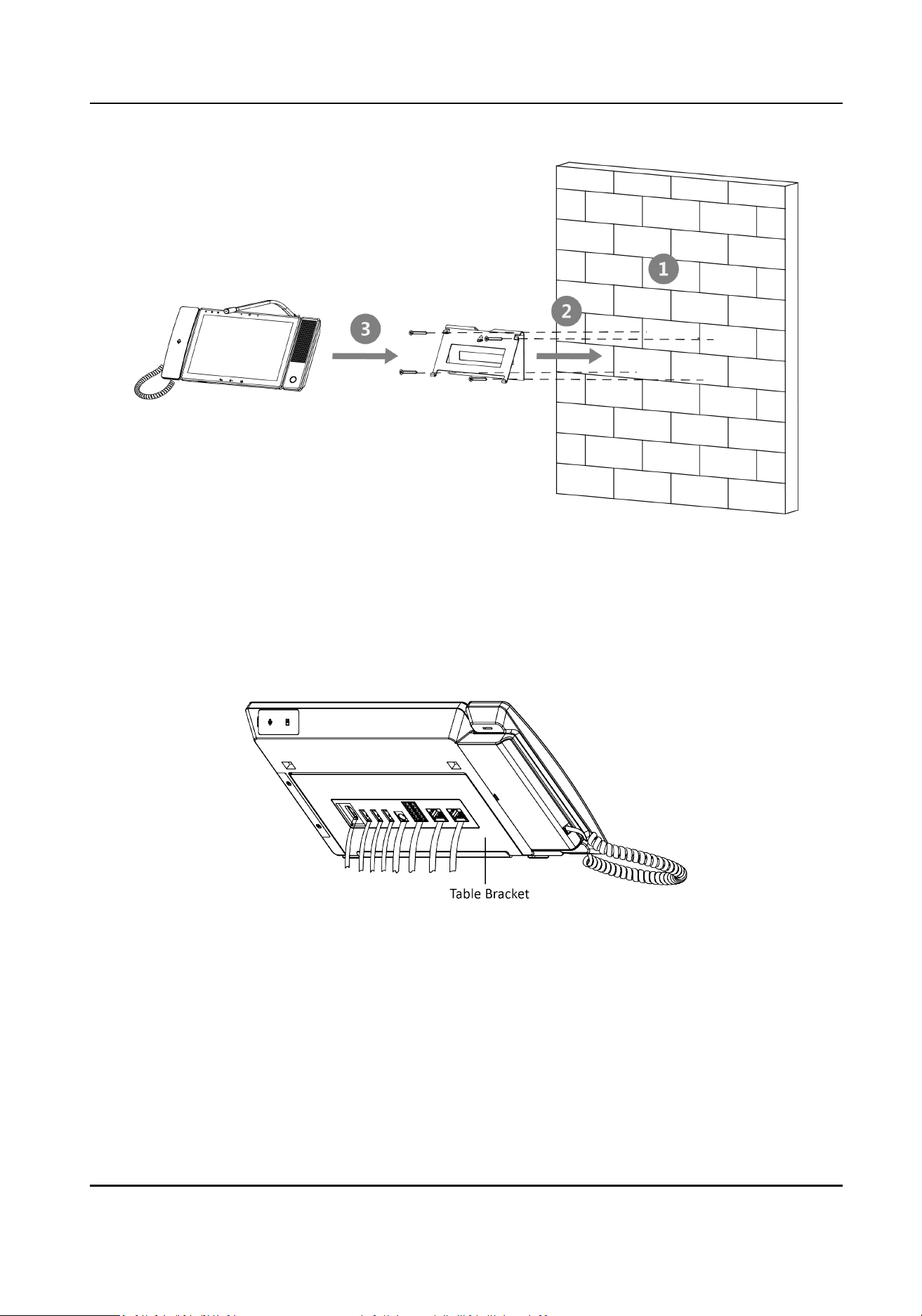
Figure 3-6 Wall Mounng
3.4 Table
Mounng
Steps
1.
Wiring the device and smooth the cables across the cable hole.
Figure 3-7 Smooth the Cable
2.
Adjust the table bracket to the right angle and put the device on the right posion.
Video Intercom Main Staon Operaon Guide
10
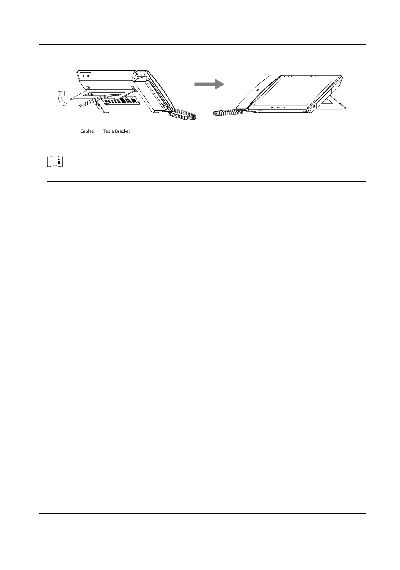
Figure 3-8 Adjust the Table Bracket
Note
Recommend the use of the table bracket: the maximum opening angle used.
Video Intercom Main Staon Operaon Guide
11
Chapter 4 Local Operaon
4.1 Call Sengs
4.1.1 Call Resident
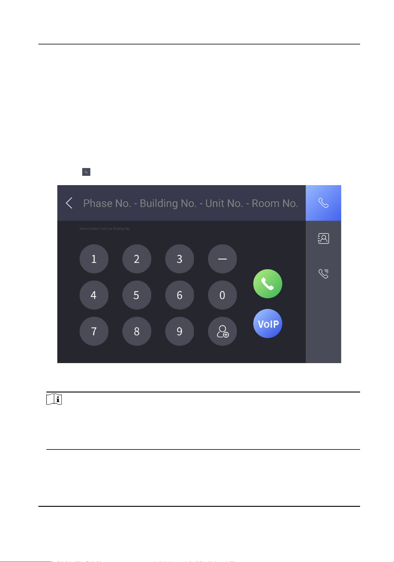
Call the indoor staon via the main staon.
Steps
1.
Tap Call → to enter the call page.
Figure 4-1 Call Page
2.
Enter the calling number to call.
Note
●
The calling number format should be x-x-x-xxx. For example, the calling number of Community
1, Building 2, Unit 3, and Room 405 is 1-2-3-405. Tap the call buon to start an audiovisual
call.
●
The community No. can be
omied.
Video Intercom Main Staon Operaon Guide
12
4.1.2 Receive Call
The main staon can receive the call from the indoor staon, the door staon, and the other main
staon.
When the main staon receives the call from the other device, tap the receive call buon to
receive the call. Or tap the hang up buon to end the call.
During the call, you can tap the unlock
buon to unlock the door remotely.
Note
The maximum call duraon between the main staon and the indoor staon is 120 s.
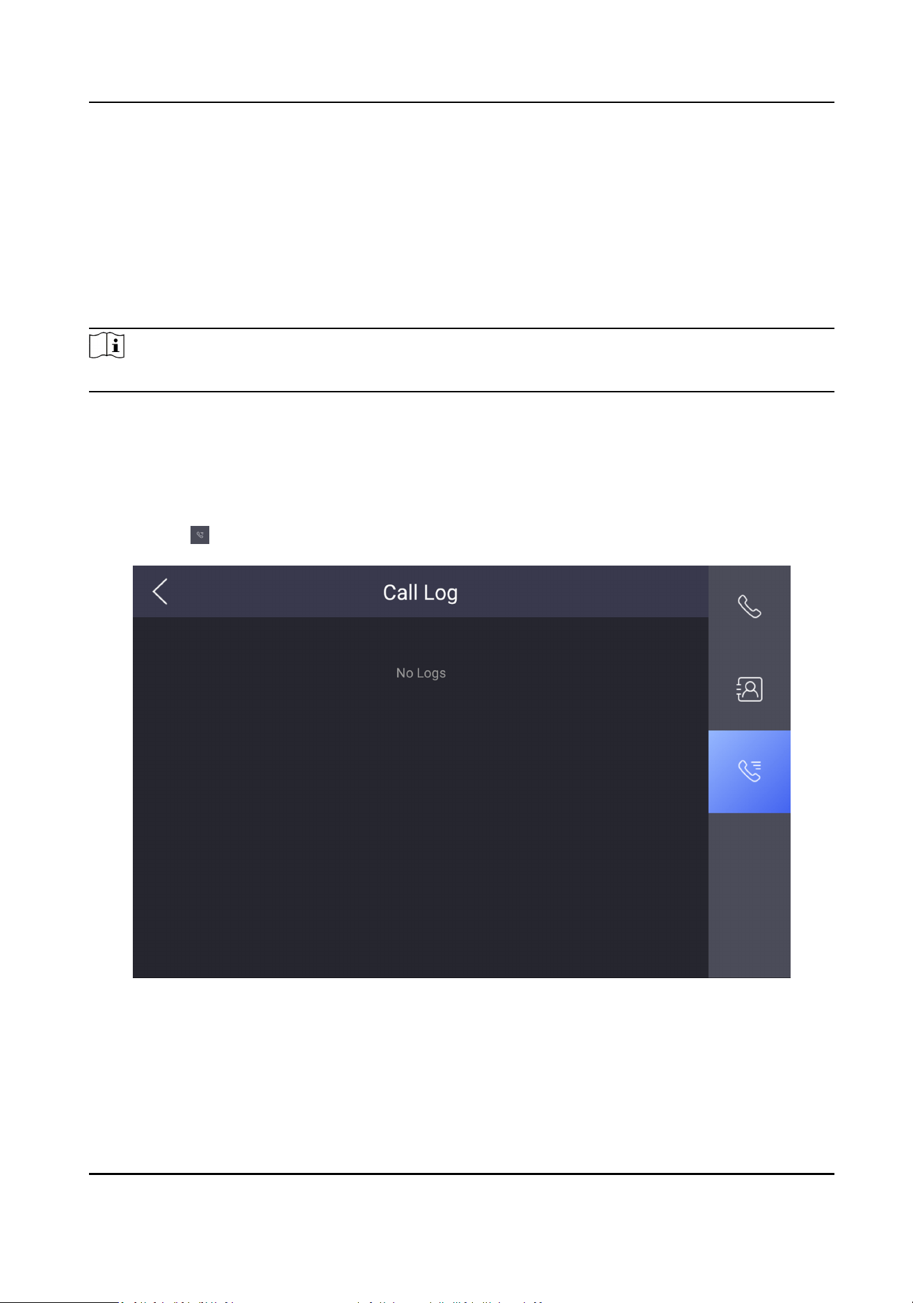
4.1.3 View Call Logs
View call logs of the main staon.
Steps
1.
Tap Call → on the main page.
Figure 4-2 Call Log Page
2.
View the call logs.
Video Intercom Main Staon Operaon Guide
13
Note
Up to 2000 call logs can be viewed.
3.
Oponal: Hold one of the call logs to clear all call logs or delete the select call log.
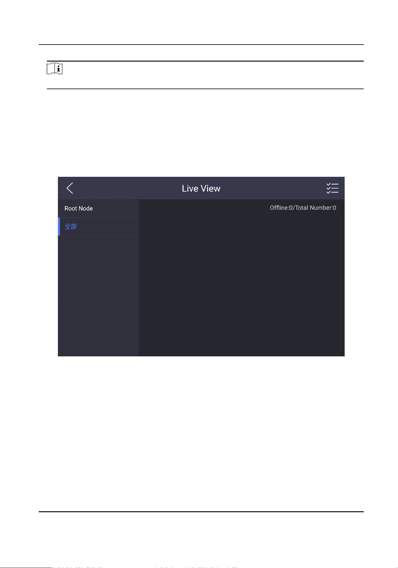
4.2 Live View
View the live videos of other devices from the main staon.
Steps
1.
Tap Live View on the main page.
Figure 4-3 Live View Page
2.
View the live videos of other devices.
3.
Oponal: Tap the unlock buon to unlock the door.
4.3 The Third-Party App
Sengs
4.3.1 Install the App
Install the third-party App to your device.
Video Intercom Main Staon Operaon Guide
14
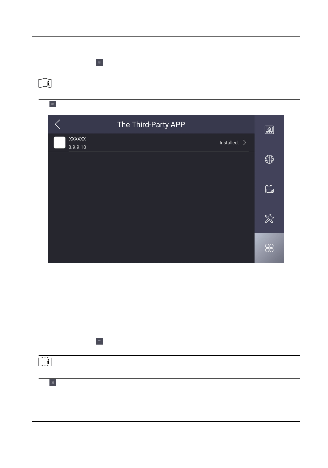
Steps
1.
Tap Conguraon → → Conguraon .
2.
Enter the conguraon password.
Note
By default, the conguraon password is the acvaon password.
3.
Tap
to view the third-party apps.
Figure 4-4 Add the Third-Party Apps
4.
Tap New APP to view the details.
5.
Oponal: Tap the added third-party app, and tap Clear Memory to clear the app's memory or
uninstall the app.
4.3.2 Uninstall the App
Steps
1.
Tap
Conguraon → → Conguraon
2.
Enter the conguraon password.
Note
By default, the conguraon password is the acvaon password.
3.
Tap to view the third-party apps.
4.
Select an App and tap Uninstall Applicaon.
Video Intercom Main Staon Operaon Guide
15

Note
You can also uninstall the Apps via client soware remotely.
4.4 Informaon Management
You can view the received alarm logs, captured pictures, recorded videos, and recorded audios.
Take viewing alarm logs as an example. Tap Message →
and you can view all received alarm
logs.
Hold one of the logs to clear all logs or delete the selected log.
Note
Up to 200 alarm logs, 200 captured pictures, 200 recorded videos, 200 recorded audios can be
viewed.
Video Intercom Main Staon Operaon Guide
16

Chapter 5 Remote Operaon via the Client Soware
The Video Intercom module provides remote control and conguraon on video intercom products
via the iVMS-4200 client
soware.
5.1 View Live Video of Door Staon and Outer Door Staon
You can get the live view of the door staon and outer door staon in the Main View module and
control the door staon and outer door staon remotely.
In the Main View module, double-click a door staon or outer door staon device or drag the
device to a display window to start the live view.
You can click Unlock on the menu to open the door remotely.
5.2 View Call Logs
You can check all the call logs, including dialed call logs, received call logs and missed call logs. You
can also directly dial via the log list and clear the logs.
Steps
1.
On the main page, click Access Control → Video Intercom to enter the Video Intercom page.
2.
Click the Call Log tab to enter the Call Log page. All the call logs will display on this page and you
can check the log
informaon, e.g., call status, start me, resident's organizaon and name,
device name and ring or speaking
duraon.
Video Intercom Main Staon Operaon Guide
17
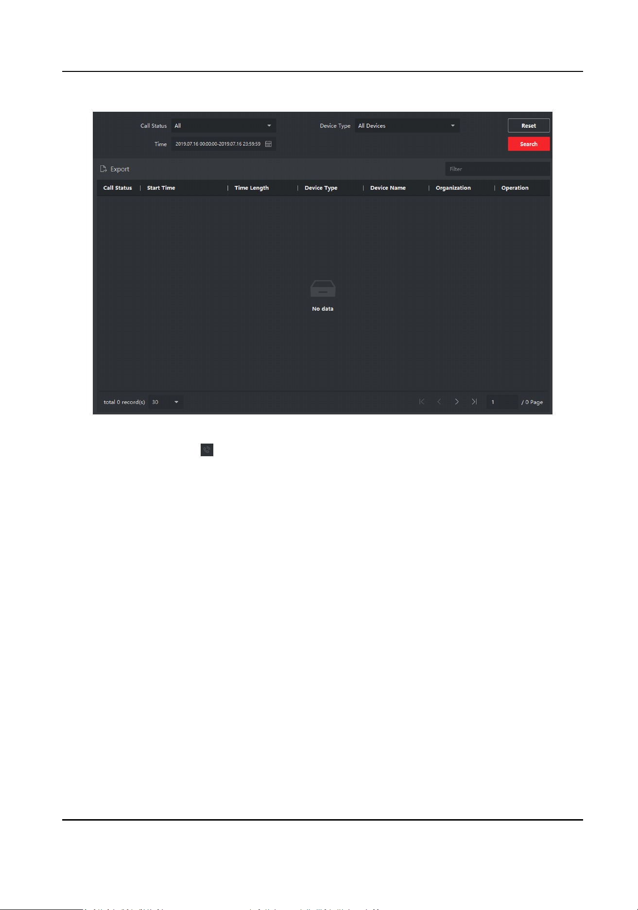
Figure 5-1 Call Log
3.
Oponal: Click the icon in the Operaon column to re-dial the resident.
5.3 Release
Noce
You can create dierent types of noces and send them to the residents. Four noce types are
available, including Adversing, Property, Alarm and Noce Informaon.
Steps
1.
On the main page, click Access Control → Video Intercom to enter the Video Intercom page.
2.
Click
Noce to enter the Release Noce page.
Video Intercom Main Staon Operaon Guide
18

Figure 5-2 Release Noce
3.
Click Add on the le panel to create a new noce.
Video Intercom Main Staon Operaon Guide
19
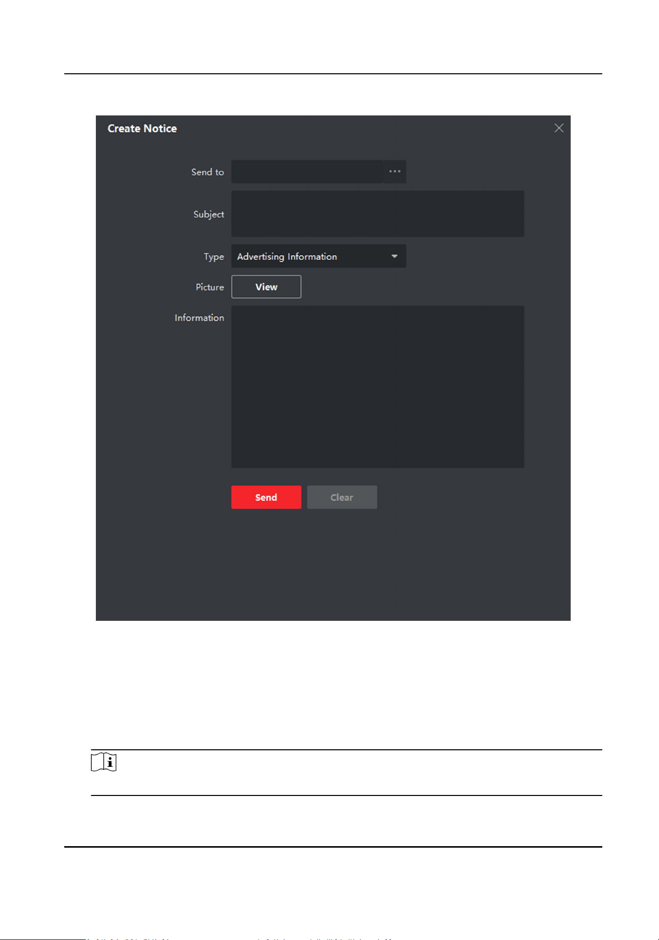
Figure 5-3 Create a Noce
4.
Edit the noce on the right panel.
1) Click ... on the Send To eld to pop up the Select Resident dialog.
2) Check the checkbox(es) to select the resident(s). Or you can check the All checkbox to select
all the added residents.
3) Click OK to save the
selecon.
4) Enter the subject on the Subject eld.
Note
Up to 63 characters are allowed in the Subject eld.
Video Intercom Main Staon Operaon Guide
20

5) Click in the Type eld to unfold the drop-down list and select the noce type.
6) Oponal: Click View to add a local picture to the noce.
Note
Up to 6 pictures in the JPGE format can be added to one noce. And the maximum size of one
picture is 512KB.
7) Enter the noce content in the Informaon eld.
8) Oponal: You can also click Clear to clear the edited content.
Note
Up to 1023 characters are allowed in the Content eld.
5.
Click Send to send the edited noce to the selected resident(s). The sent noce informaon will
display on the le panel. You can click a noce to view the details on the right panel.
5.4 Search Video Intercom
Informaon
You can search the call logs between the iVMS-4200 client soware and video intercom devices,
device unlocking logs and the sent noce informaon.
On the main page, click Access Control to enter the access control module.
In the Access Control module, click Video Intercom to enter the Video Intercom page.
5.4.1 Search Call Logs
Steps
1.
On the main page, click Access Control → Video Intercom to enter the Video Intercom page.
2.
Click Call Log to enter the Call Log page.
Video Intercom Main Staon Operaon Guide
21
Figure 5-4 Search Call Logs
3.
Set the search condions, including call status, device type, start me and end me.
Call Status
Click to unfold the drop-down list and select the call status as Dialed, Received or Missed.
Or select All to search logs with all statuses.
Device Type
Click
to unfold the drop-down list and select the device type as Indoor Staon, Door
Staon, Outer Door Staon or Analog Indoor Staon. Or select All Devices to search logs
with all device types.
Start Time/End Time
Click
to specify the start me and end me of a me period to search the logs.
4.
Oponal: You can click Reset to reset all the congured search condions.
5.
Click Search and all the matched call logs will display on this page.
●
Check the detailed
informaon of searched call logs, such as call status, ring/speaking
duraon, device name, resident organizaon, etc.
●
Input keywords in the Search
eld to lter the desired log.
●
Click Export to export the call logs to your PC.
Video Intercom Main Staon Operaon Guide
22
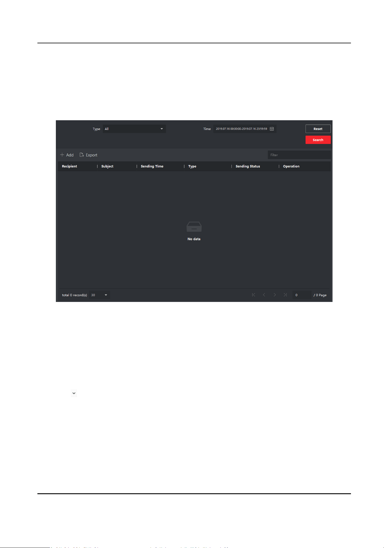
5.4.2 Search Noce
Steps
1.
On the main page, click Access Control → Video Intercom to enter the Video Intercom page.
2.
Click
Noce to enter the Noce page.
Figure 5-5 Search Noce
3.
Set the search condions, including noce type, subject, recipient, start me and end me.
Recipient
Input the recipient informaon in the Recipient eld to search the specied noce.
Subject
Input the keywords in the Subject eld to search the matched noce.
Type
Click to unfold the drop-down list and select the noce type as Adversing Informaon ,
Property Informaon, Alarm Informaon or Noce Informaon. Or select All to search
noces with all types.
4.
Oponal: You can click Reset to reset all the congured search condions.
5.
Click Search and all the matched noces will display on this page.
●
Check the detailed informaon of searched noces, such as sending me, sending status, etc.
●
Input keywords in the Search
eld to lter the searching result.
Video Intercom Main Staon Operaon Guide
23

6.
You can view and edit the noce details, check the sending failed/sent succeeded/unread users,
and resend the noce to sending failed/unread users.
7.
Oponal: Click Export to export the noces to your PC.
Video Intercom Main Staon Operaon Guide
24

Appendix A. Communicaon Matrix and Device
Command
Communicaon Matrix
Scan the following QR code to get the device communicaon matrix.
Note that the matrix contains all
communicaon ports of Hikvision access control and video
intercom devices.
Figure A-1 QR Code of Communicaon Matrix
Device Command
Scan the following QR code to get the device common serial port commands.
Note that the command list contains all commonly used serial ports commands for all Hikvision
access control and video intercom devices.
Figure A-2 Device Command
Video Intercom Main Staon Operaon Guide
25

UD21586B
