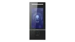

Video Intercom Face Recognion
Door Staon
User Manual

Legal Informaon
©2019 Hangzhou Hikvision Digital Technology Co., Ltd. All rights reserved.
About this Manual
The Manual includes instrucons for using and managing the Product.
Pictures, charts, images and all other informaon hereinaer are for
descripon and explanaon only. The informaon contained in the Manual
is subject to change, without noce, due to rmware updates or other
reasons. Please nd the latest version of this Manual at the Hikvision
website (
hps://www.hikvision.com/ ).
Please use this Manual with the guidance and assistance of professionals
trained in supporng the Product.
Trademarks
and other Hikvision's trademarks and logos are the
properes of Hikvision in various jurisdicons.
Other trademarks and logos menoned are the properes of their
respecve owners.
Disclaimer
TO THE MAXIMUM EXTENT PERMITTED BY APPLICABLE LAW, THIS MANUAL
AND THE PRODUCT DESCRIBED, WITH ITS HARDWARE, SOFTWARE AND
FIRMWARE, ARE PROVIDED “AS IS” AND “WITH ALL FAULTS AND ERRORS”.
HIKVISION MAKES NO WARRANTIES, EXPRESS OR IMPLIED, INCLUDING
WITHOUT LIMITATION, MERCHANTABILITY, SATISFACTORY QUALITY, OR
FITNESS FOR A PARTICULAR PURPOSE. THE USE OF THE PRODUCT BY YOU IS
AT YOUR OWN RISK. IN NO EVENT WILL HIKVISION BE LIABLE TO YOU FOR
ANY SPECIAL, CONSEQUENTIAL, INCIDENTAL, OR INDIRECT DAMAGES,
INCLUDING, AMONG OTHERS, DAMAGES FOR LOSS OF BUSINESS PROFITS,
BUSINESS INTERRUPTION, OR LOSS OF DATA, CORRUPTION OF SYSTEMS, OR
LOSS OF DOCUMENTATION, WHETHER BASED ON BREACH OF CONTRACT,
TORT (INCLUDING NEGLIGENCE), PRODUCT LIABILITY, OR OTHERWISE, IN
Video Intercom Face Recognion Door Staon User Manual
i

CONNECTION WITH THE USE OF THE PRODUCT, EVEN IF HIKVISION HAS
BEEN ADVISED OF THE POSSIBILITY OF SUCH DAMAGES OR LOSS.
YOU ACKNOWLEDGE THAT THE NATURE OF INTERNET PROVIDES FOR
INHERENT SECURITY RISKS, AND HIKVISION SHALL NOT TAKE ANY
RESPONSIBILITIES FOR ABNORMAL OPERATION, PRIVACY LEAKAGE OR
OTHER DAMAGES RESULTING FROM CYBER-ATTACK, HACKER ATTACK, VIRUS
INSPECTION, OR OTHER INTERNET SECURITY RISKS; HOWEVER, HIKVISION
WILL PROVIDE TIMELY TECHNICAL SUPPORT IF REQUIRED.
YOU AGREE TO USE THIS PRODUCT IN COMPLIANCE WITH ALL APPLICABLE
LAWS, AND YOU ARE SOLELY RESPONSIBLE FOR ENSURING THAT YOUR USE
CONFORMS TO THE APPLICABLE LAW. ESPECIALLY, YOU ARE RESPONSIBLE,
FOR USING THIS PRODUCT IN A MANNER THAT DOES NOT INFRINGE ON THE
RIGHTS OF THIRD PARTIES, INCLUDING WITHOUT LIMITATION, RIGHTS OF
PUBLICITY, INTELLECTUAL PROPERTY RIGHTS, OR DATA PROTECTION AND
OTHER PRIVACY RIGHTS. YOU SHALL NOT USE THIS PRODUCT FOR ANY
PROHIBITED END-USES, INCLUDING THE DEVELOPMENT OR PRODUCTION
OF WEAPONS OF MASS DESTRUCTION, THE DEVELOPMENT OR
PRODUCTION OF CHEMICAL OR BIOLOGICAL WEAPONS, ANY ACTIVITIES IN
THE CONTEXT RELATED TO ANY NUCLEAR EXPLOSIVE OR UNSAFE NUCLEAR
FUEL-CYCLE, OR IN SUPPORT OF HUMAN RIGHTS ABUSES.
IN THE EVENT OF ANY CONFLICTS BETWEEN THIS MANUAL AND THE
APPLICABLE LAW, THE LATER PREVAILS.
Data Protecon
During the use of device, personal data will be collected, stored and
processed. To protect data, the development of Hikvision devices
incorporates privacy by design principles. For example, for device with facial
recognion features, biometrics data is stored in your device with
encrypon method; for ngerprint device, only ngerprint template will be
saved, which is impossible to reconstruct a ngerprint image.
As data controller, you are advised to collect, store, process and transfer
data in accordance with the applicable data protecon laws and regulaons,
including without limitaon, conducng security controls to safeguard
personal data, such as, implemenng reasonable administrave and
physical security controls, conduct periodic reviews and assessments of the
eecveness of your security controls.
Video Intercom Face Recognion Door Staon User Manual
ii
Symbol Convenons
The symbols that may be found in this document are dened as follows.
Symbol Descripon
Danger
Indicates a hazardous situaon which, if not avoided, will or
could result in death or serious injury.
Cauon
Indicates a potenally hazardous situaon which, if not
avoided, could result in equipment damage, data loss,
performance degradaon, or unexpected results.
Note
Provides addional informaon to emphasize or
supplement important points of the main text.
Video Intercom Face Recognion Door Staon User Manual
iii

Safety Instrucon
Warning
●
All the electronic operaon should be strictly compliance with the electrical safety
regulaons, re prevenon regulaons and other related regulaons in your local
region.
●
Please use the power adapter, which is provided by normal company. The power
consumpon cannot be less than the required value.
●
Do not connect several devices to one power adapter as adapter overload may
cause over-heat or re hazard.
●
Please make sure that the power has been disconnected before you wire, install or
dismantle the device.
●
When the product is installed on wall or ceiling, the device shall be rmly xed.
●
If smoke, odors or noise rise from the device, turn o the power at once and
unplug the power cable, and then please contact the service center.
●
If the product does not work properly, please contact your dealer or the nearest
service center. Never aempt to disassemble the device yourself. (We shall not
assume any responsibility for problems caused by unauthorized repair or
maintenance.)
Cauon
●
Do not drop the device or subject it to physical shock, and do not expose it to high
electromagnesm radiaon. Avoid the equipment installaon on vibraons
surface or places subject to shock (ignorance can cause equipment damage).
●
Do not place the device in extremely hot (refer to the specicaon of the device
for the detailed operang temperature), cold, dusty or damp locaons, and do not
expose it to high electromagnec radiaon.
●
The device cover for indoor use shall be kept from rain and moisture.
●
Exposing the equipment to direct sun light, low venlaon or heat source such as
heater or radiator is forbidden (ignorance can cause re danger).
●
Do not aim the device at the sun or extra bright places. A blooming or smear may
occur otherwise (which is not a malfuncon however), and aecng the
endurance of sensor at the same me.
Video Intercom Face Recognion Door Staon User Manual
iv

●
Please use the provided glove when open up the device cover, avoid direct contact
with the device cover, because the acidic sweat of the ngers may erode the
surface coang of the device cover.
●
Please use a so and dry cloth when clean inside and outside surfaces of the
device cover, do not use alkaline detergents.
●
Please keep all wrappers aer unpack them for future use. In case of any failure
occurred, you need to return the device to the factory with the original wrapper.
Transportaon without the original wrapper may result in damage on the device
and lead to addional costs.
●
Improper use or replacement of the baery may result in hazard of explosion.
Replace with the same or equivalent type only. Dispose of used baeries
according to the instrucons provided by the baery manufacturer.
●
Improper replacement of the baery with an incorrect type may defeat a
safeguard (for example, in case of some lithium baery types).
●
Do not dispose of the baery into re or a hot oven, or mechanically crush or cut
the baery, which may result in an explosion.
●
Do not leave the baery in an extremely high temperature surrounding
environment, which may result in an explosion or leakage of ammable liquid or
gas.
●
Do not subject the baery to extremely low air pressure, which may result in an
explosion or the leakage of ammable liquid or gas.
●
CAUTION: Risk of explosion if the baery is replaced by an incorrect type.
Video Intercom Face Recognion Door Staon User Manual
v

Regulatory Informaon
FCC Informaon
Please take aenon that changes or modicaon not expressly approved
by the party responsible for compliance could void the user’s authority to
operate the equipment.
FCC compliance: This equipment has been tested and found to comply with
the limits for a Class B digital device, pursuant to part 15 of the FCC Rules.
These limits are designed to provide reasonable protecon against harmful
interference in a residenal installaon. This equipment generates, uses and
can radiate radio frequency energy and, if not installed and used in
accordance with the instrucons, may cause harmful interference to radio
communicaons. However, there is no guarantee that interference will not
occur in a parcular installaon. If this equipment does cause harmful
interference to radio or television recepon, which can be determined by
turning the equipment o and on, the user is encouraged to try to correct
the interference by one or more of the following measures:
—Reorient or relocate the receiving antenna.
—Increase the separaon between the equipment and receiver.
—Connect the equipment into an outlet on a circuit dierent from that to
which the receiver is connected.
—Consult the dealer or an experienced radio/TV technician for help
FCC Condions
This device complies with part 15 of the FCC Rules. Operaon is subject to
the following two condions:
1. This device may not cause harmful interference.
2. This device must accept any interference received, including interference
that may cause undesired operaon.
This equipment complies with FCC/IC RSS-102 radiaon exposure limits set
forth for an uncontrolled environment. This equipment should be installed
and operated with minimum distance 20cm between the radiator & your
body.
Video Intercom Face Recognion Door Staon User Manual
vi
ce matériel est conforme aux limites de dose d'exposion aux
rayonnements, FCC / CNR-102 énoncée dans un autre environnement.cee
eqipment devrait être installé et exploité avec distance minimale de 20
entre le radiateur et votre corps.
EU Conformity Statement
This product and - if applicable - the supplied accessories too are
marked with "CE" and comply therefore with the applicable
harmonized European standards listed under the EMC Direcve
2014/30/EU, the RoHS Direcve 2011/65/EU
2012/19/EU (WEEE direcve): Products marked with this symbol
cannot be disposed of as unsorted municipal waste in the
European Union. For proper recycling, return this product to your
local supplier upon the purchase of equivalent new equipment, or
dispose of it at designated collecon points. For more informaon
see: www.recyclethis.info
2006/66/EC (baery direcve): This product contains a baery
that cannot be disposed of as unsorted municipal waste in the
European Union. See the product documentaon for specic
baery informaon. The baery is marked with this symbol,
which may include leering to indicate cadmium (Cd), lead (Pb),
or mercury (Hg). For proper recycling, return the baery to your
supplier or to a designated collecon point. For more informaon
see:www.recyclethis.info
Industry Canada ICES-003 Compliance
This device meets the CAN ICES-3 (B)/NMB-3(B) standards requirements.
This device complies with Industry Canada licence-exempt RSS standard(s).
Operaon is subject to the following two condions:
Video Intercom Face Recognion Door Staon User Manual
vii

1.
this device may not cause interference, and
2.
this device must accept any interference, including interference that may
cause undesired operaon of the device.
Le présent appareil est conforme aux CNR d'Industrie Canada applicables
aux appareils radioexempts de licence. L'exploitaon est autorisée aux deux
condions suivantes :
1.
l'appareil ne doit pas produire de brouillage, et
2.
l'ulisateur de l'appareil doit accepter tout brouillage radioélectrique
subi, même si le brouillage est suscepble d'en compromere le
fonconnement.
Under Industry Canada regulaons, this radio transmier may only operate
using an antenna of a type and maximum (or lesser) gain approved for the
transmier by Industry Canada. To reduce potenal radio interference to
other users, the antenna type and its gain should be so chosen that the
equivalent isotropically radiated power (e.i.r.p.) is not more than that
necessary for successful communicaon.
Conformément à la réglementaon d'Industrie Canada, le présent émeeur
radio peut fonconner avec une antenne d'un type et d'un gain maximal (ou
inférieur) approuvé pour l'émeeur par Industrie Canada. Dans le but de
réduire les risques de brouillage radioélectrique à l'intenon des autres
ulisateurs, il faut choisir le type d'antenne et son gain de sorte que la
puissance isotrope rayonnée équivalente (p.i.r.e.) ne dépasse pas l'intensité
nécessaire à l'établissement d'une communicaon sasfaisante.
This equipment should be installed and operated with a minimum distance
20cm between the radiator and your body.
Cet équipement doit être installé et ulisé à une distance minimale de 20
cm entre le radiateur et votre corps.
Video Intercom Face Recognion Door Staon User Manual
viii

Contents
1 Appearance ................................................................................................ 1
2 Terminal and Wiring Descripon ................................................................ 3
2.1 Terminal Descripon ......................................................................................... 3
2.2 Wiring Descripon ............................................................................................ 5
2.2.1 Door Lock Wiring ...................................................................................... 5
2.2.2 Door Contact Wiring ................................................................................. 5
2.2.3 External Card Reader Wiring .................................................................... 6
2.2.4 Alarm Device Input Wiring ....................................................................... 8
2.2.5 Alarm Device Output Wiring .................................................................... 9
3 Installaon ................................................................................................ 10
3.1 Juncon Box (Sales Seperately) ....................................................................... 10
3.2 Wall Mounng with Juncon Box ................................................................... 11
4 Acvaon ................................................................................................. 12
4.1 Acvate Device Locally .................................................................................... 12
4.2 Acvate Device via Client Soware ................................................................. 13
5 Local Operaon ........................................................................................ 15
5.1 Local Conguraon ......................................................................................... 15
5.1.1 Network Sengs .................................................................................... 15
5.1.2 Informaon Sengs ............................................................................... 15
5.1.3 Add Residents ......................................................................................... 16
5.1.4 Recognion Parameters Sengs ............................................................ 17
5.1.5 Change Password .................................................................................... 17
Video Intercom Face Recognion Door Staon User Manual
ix

5.1.6 Volume Adjustment ................................................................................ 18
5.1.7 Search Version ........................................................................................ 18
5.2 Video Intercom Operaon .............................................................................. 19
5.2.1 Call Resident ........................................................................................... 19
5.2.2 Call Center .............................................................................................. 19
5.3 Unlock Door .................................................................................................... 19
5.3.1 Unlock by Password ................................................................................ 19
5.3.2 Unlock by Presenng Card ...................................................................... 20
5.3.3 Unlock by Fingerprint ............................................................................. 20
5.3.4 Unlock by Face ........................................................................................ 20
6 Conguraon via Client Soware ............................................................. 21
6.1 Edit Network Parameters ................................................................................ 21
6.2 Add Device ...................................................................................................... 21
6.2.1 Add Online Device .................................................................................. 21
6.2.2 Add Device by IP Address ....................................................................... 22
6.2.3 Add Device by IP Segment ...................................................................... 22
6.3 Remote Conguraon ..................................................................................... 23
6.3.1 System .................................................................................................... 23
6.3.2 Video Intercom ....................................................................................... 28
6.3.3 Network Sengs .................................................................................... 34
6.3.4 Video Display Sengs ............................................................................ 37
6.4 Device Management ....................................................................................... 39
6.5 Organizaon Management ............................................................................. 39
6.5.1 Add Organizaon .................................................................................... 39
Video Intercom Face Recognion Door Staon User Manual
x

6.5.2 Modify and Delete Organizaon ............................................................. 40
6.6 Person Management ....................................................................................... 40
6.6.1 Add Person ............................................................................................. 40
6.6.2 Modify and Delete Person ...................................................................... 42
6.6.3 Import and Export Person Informaon .................................................. 42
6.6.4 Get Person Informaon from Device ...................................................... 42
6.6.5 Change Person to Other Organizaon .................................................... 43
6.6.6 Add Person in Batch ................................................................................ 43
6.6.7 Issue Card in Batch ................................................................................. 44
6.6.8 Permission Sengs ................................................................................. 45
6.7 Video Intercom Sengs .................................................................................. 46
6.7.1 Receive Call from Door Staon ............................................................... 46
6.7.2 Live View via Door Staon ...................................................................... 47
6.7.3 Release Noce ........................................................................................ 47
6.7.4 Search Video Intercom Informaon ....................................................... 48
Video Intercom Face Recognion Door Staon User Manual
xi
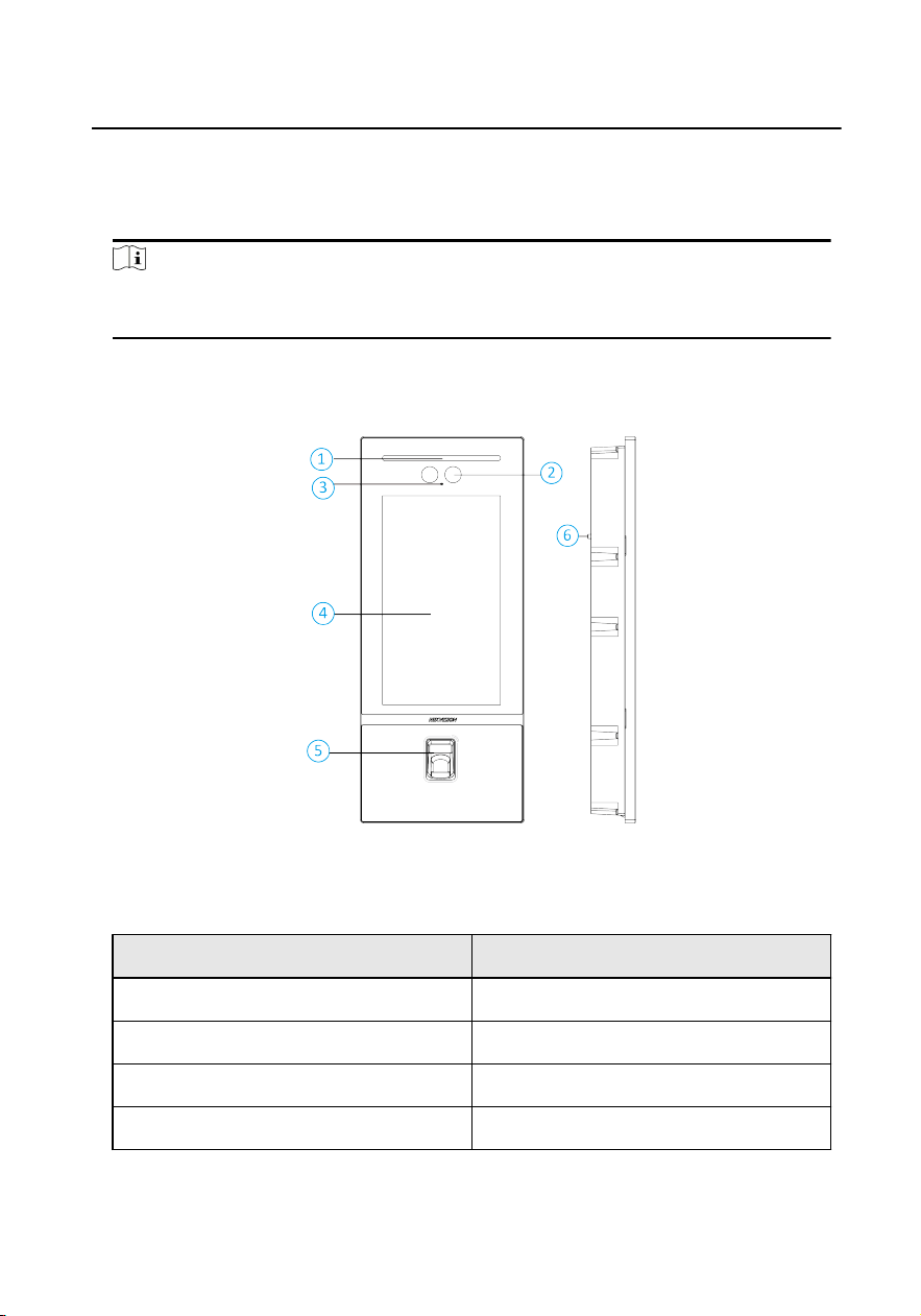
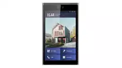
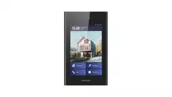
1 Appearance
Note
The appearance of the device vary according to dierent model. Refers to actual
device.
With Fingerprint Module
Figure 1-1 Front and Side Panel
Table 1-1 Appearance and Descripon
No. Descripon
1 Light
2 Camera
3 Microphone
4 Screen
Video Intercom Face Recognion Door Staon User Manual
1
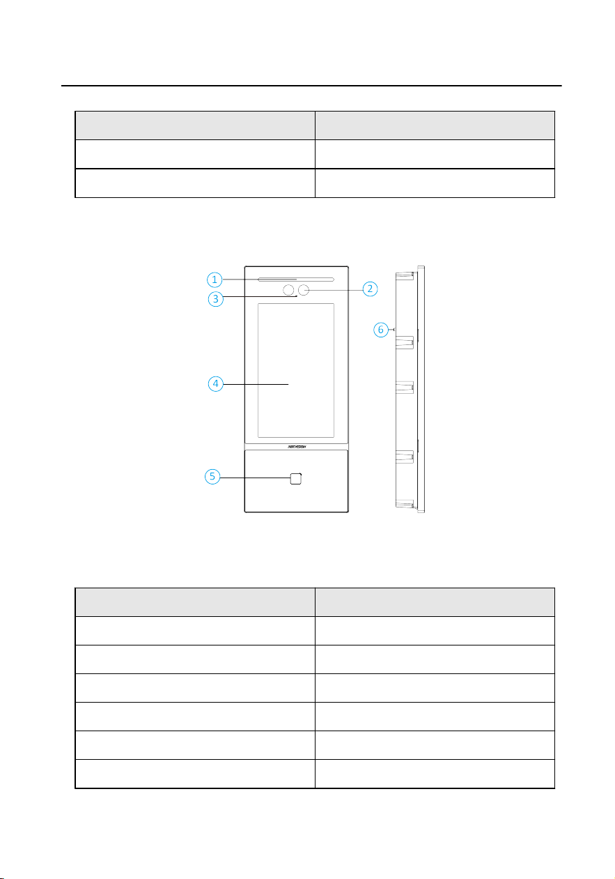
No. Descripon
5 Fingerprint Reconion Area
6 TAMPER
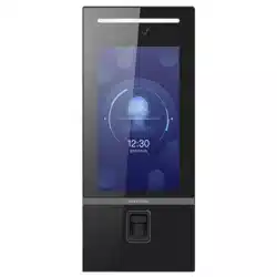
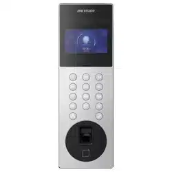
With Card Reader Module
Figure 1-2 Front and Side Panel
Table 1-2 Appearance and Descripon
No. Descripon
1 Light
2 Camera
3 Microphone
4 Screen
5 Card Reader Area
6 TAMPER
Video Intercom Face Recognion Door Staon User Manual
2
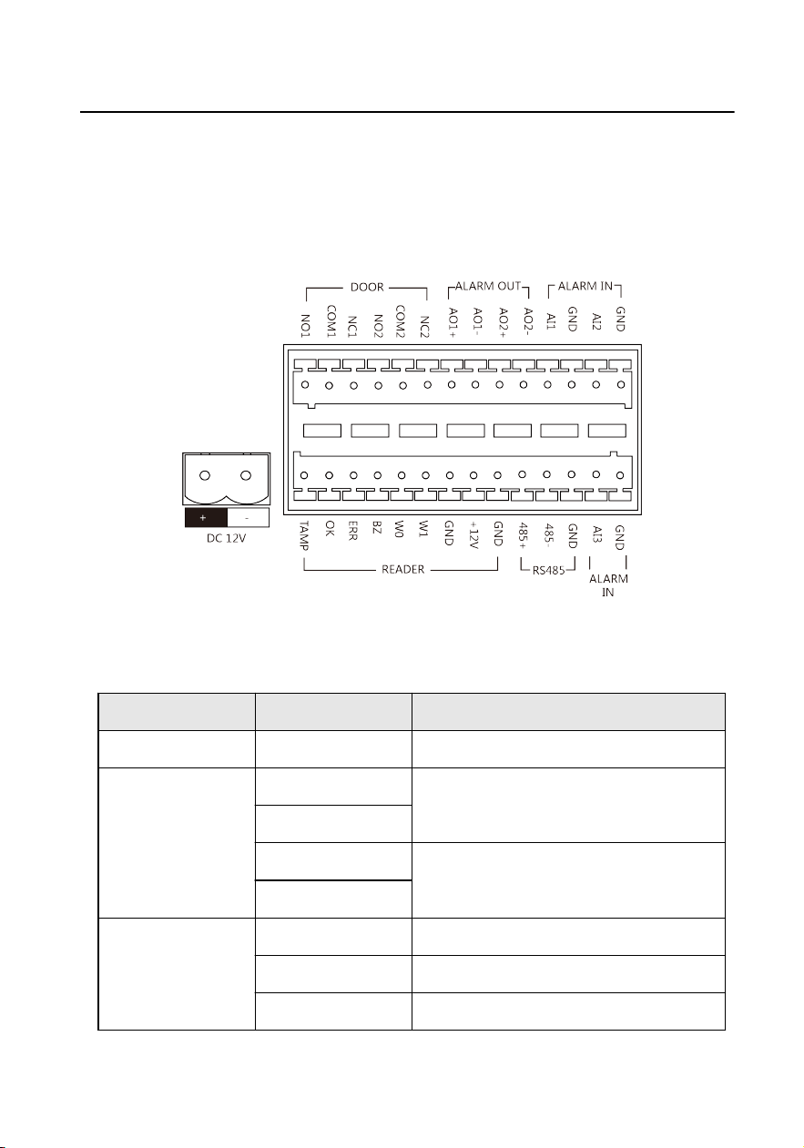
2 Terminal and Wiring Descripon
2.1 Terminal Descripon
Figure 2-1 Terminal Descripon
Table 2-1 Descripon of Terminal and Interface
Name Interface Descripon
Power Input DC 12 V 12 VDC Power Input
ALARM OUT AO1+ Alarm Relay Output 1
AO1-
AO2+ Alarm Relay Output 2
AO2-
ALARM IN AI1 Alarm Input 1
AI2 Alarm Input 2
AI3 Alarm Input 3
Video Intercom Face Recognion Door Staon User Manual
3
Name Interface Descripon
GND Grounding
RS-485 485+ RS-485 Communicaon Terminal
485-
GND
READER TAMP Wiegand Card Reader TAMPER
OK Card Reader Indicator Output (Valid
Card Output)
ERR Card Reader Indicator Output (Invaild
Card Output)
BZ Card Reader Buzzer Output
W0 Data Input Interface Wiegand Card
Reader: Data0
W1 Data Input Interface Wiegand Card
Reader: Data1
GND Grounding
12V Power Supply Output
GND Grounding
DOOR NO1 Door Lock Relay Output 1
COM1 Common Interface
NC1 Door Lock Relay Output 1
NO2 Door Lock Relay Output 2
COM2 Common Interface
NC2 Door Lock Relay Output 2
Video Intercom Face Recognion Door Staon User Manual
4
2.2 Wiring Descripon
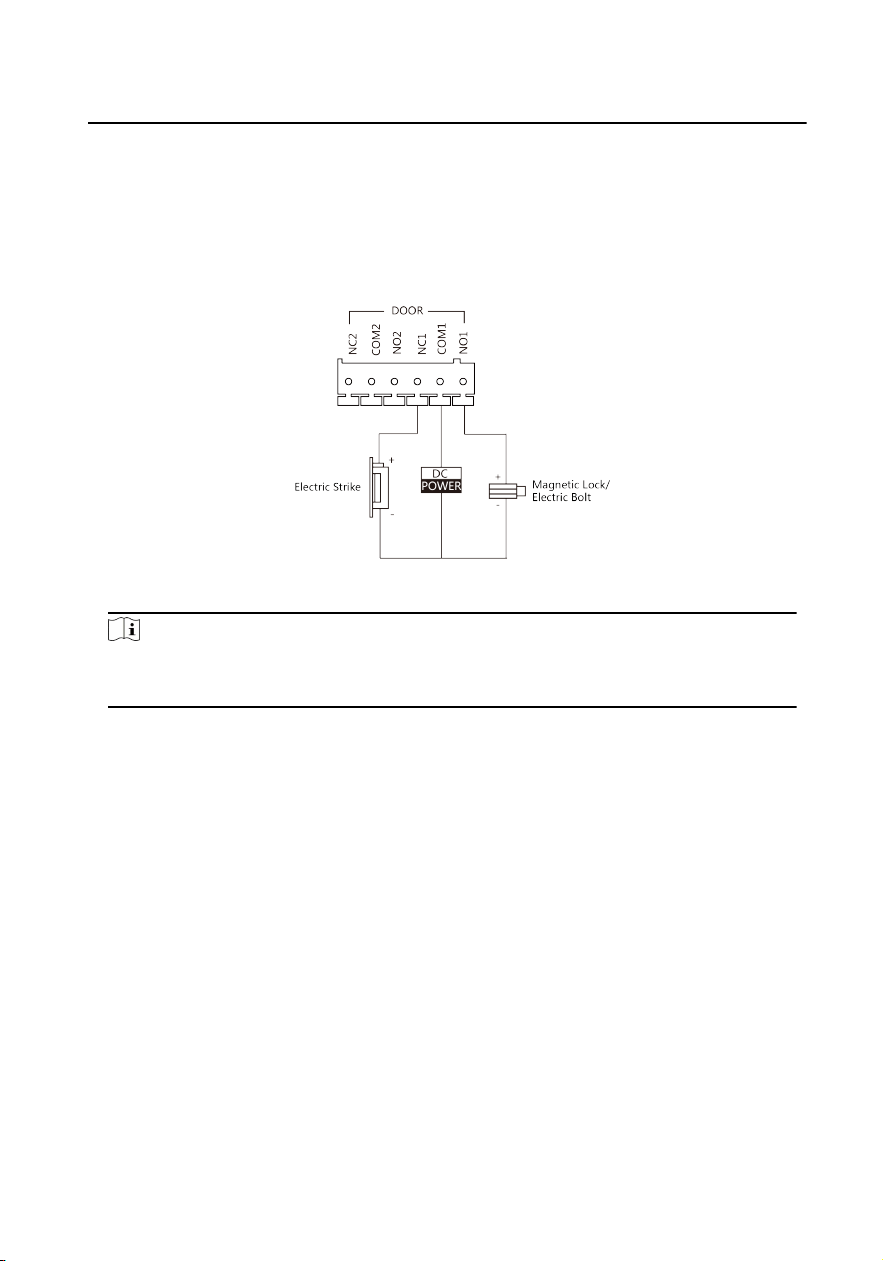
2.2.1 Door Lock Wiring
Figure 2-2 Door Lock Wiring
Note
Terminal NC1/COM1 is set as default for accessing electric strike. Terminal NO1/
COM1 is set as default for accessing magnec lock/electric bolt.
2.2.2 Door Contact Wiring
Video Intercom Face Recognion Door Staon User Manual
5
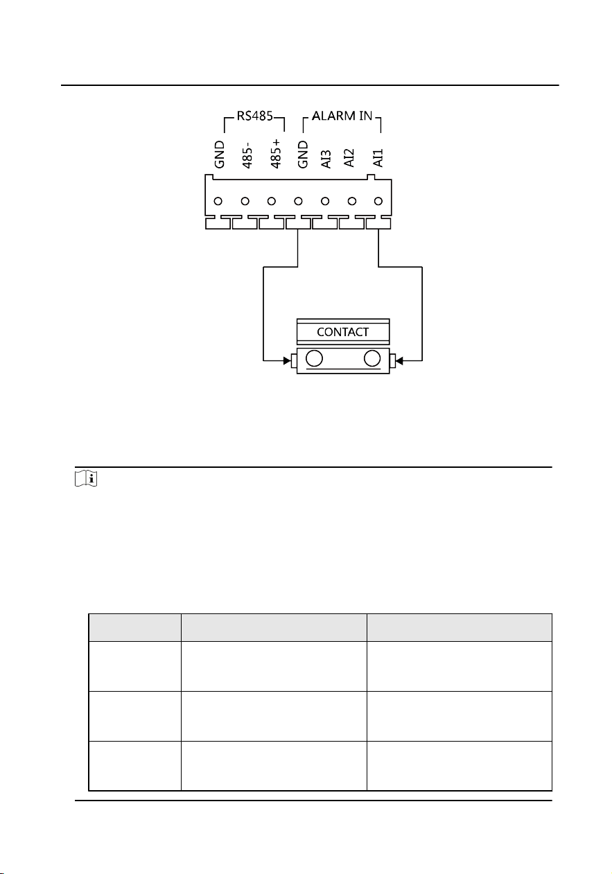
Figure 2-3 Door Contact Wiring
2.2.3 External Card Reader Wiring
Note
●
Please set the DIP switch rst before connecng the card reader.
●
If the DIP switch should be congured when the card reader is power-on, please
reboot the card reader aer conguring the DIP switch.
●
The DIP switch descripon is shown in the following table:
Table 2-2 DIP Switch Descripon
No. Descripon How to Congure
1 to 4 Set the RS-485 address ON: 1
OFF: 0
6 Select Wiegand protocol or RS-
485 protocol
ON: Wiegand
OFF: RS-485
7 Set the Wiegand protocol (It is
invalid when seng OFF in 6.)
ON: Wiegand 26
OFF: Wiegand 34
Video Intercom Face Recognion Door Staon User Manual
6
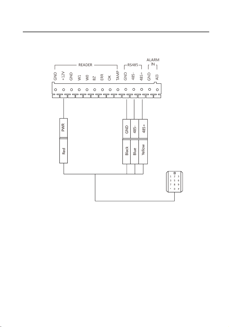
RS-485 Card Reader Wiring
Figure 2-4 RS-485 Card Reader Wiring
Video Intercom Face Recognion Door Staon User Manual
7
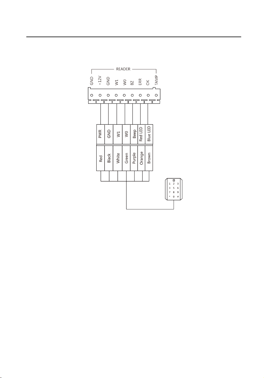
Wiegand Card Reader Wiring
Figure 2-5 Wiegand Card Reader Wiring
2.2.4 Alarm Device Input Wiring
Video Intercom Face Recognion Door Staon User Manual
8
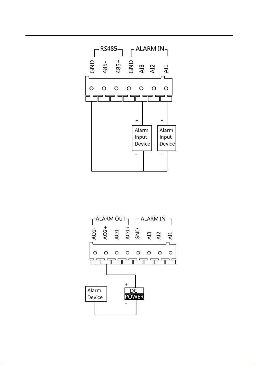
Figure 2-6 Alarm Device Input Wiring
2.2.5 Alarm Device Output Wiring
Figure 2-7 Alarm Device Output Wiring
Video Intercom Face Recognion Door Staon User Manual
9
3 Installaon
Note
●
Make sure the device in the package is in good condion and all the assembly
parts are included.
●
The power supply the door staon supports is 12 VDC. Please make sure your
power supply matches your door staon.
●
Make sure all the related equipment is power-o during the installaon.
●
Check the product specicaon for the installaon environment.
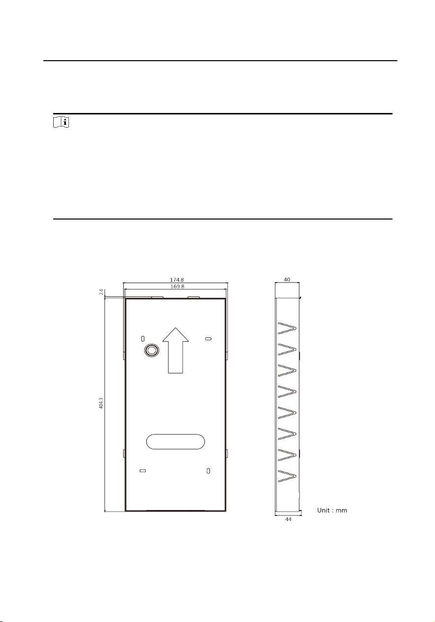
3.1 Juncon Box (Sales Seperately)
Figure 3-1 Juncon Box
Video Intercom Face Recognion Door Staon User Manual
10
Note
●
Ask our technique supports and sales and purchase the DS-KABD9613-G juncon
box.
●
The dimension of the juncon box is: 406.7 mm(W) × 174.8 mm(H) × 44 mm(D).
●
The installaon hole should be larger than juncon box. The suggested dimension
of the installaon hole is 407.5mm(W) × 175.5(H) × 44.5(D) mm.
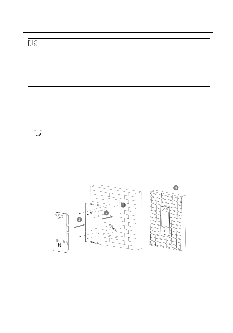
3.2 Wall Mounng with Juncon Box
Steps
1. Drill an installaon hole on the wall.
Note
The suggested size of hole is 407.5mm(W) × 175.5(H) × 44.5(D) mm.
2. Insert the juncon box to the wall. Secure the juncon and the wall with 4
supplied screws.
3. Insert the door staon to the juncon box.
4. Fix the door staon with the set screw.
Figure 3-2 Wall Mounng with Juncon Box
Video Intercom Face Recognion Door Staon User Manual
11
4 Acvaon
4.1 Acvate Device Locally
You are required to acvate the device rst by sengs a strong password for it
before you can use the device.
Steps
1. Power on the device to enter the acvaon page automacally.
2. Create a password and conrm it.
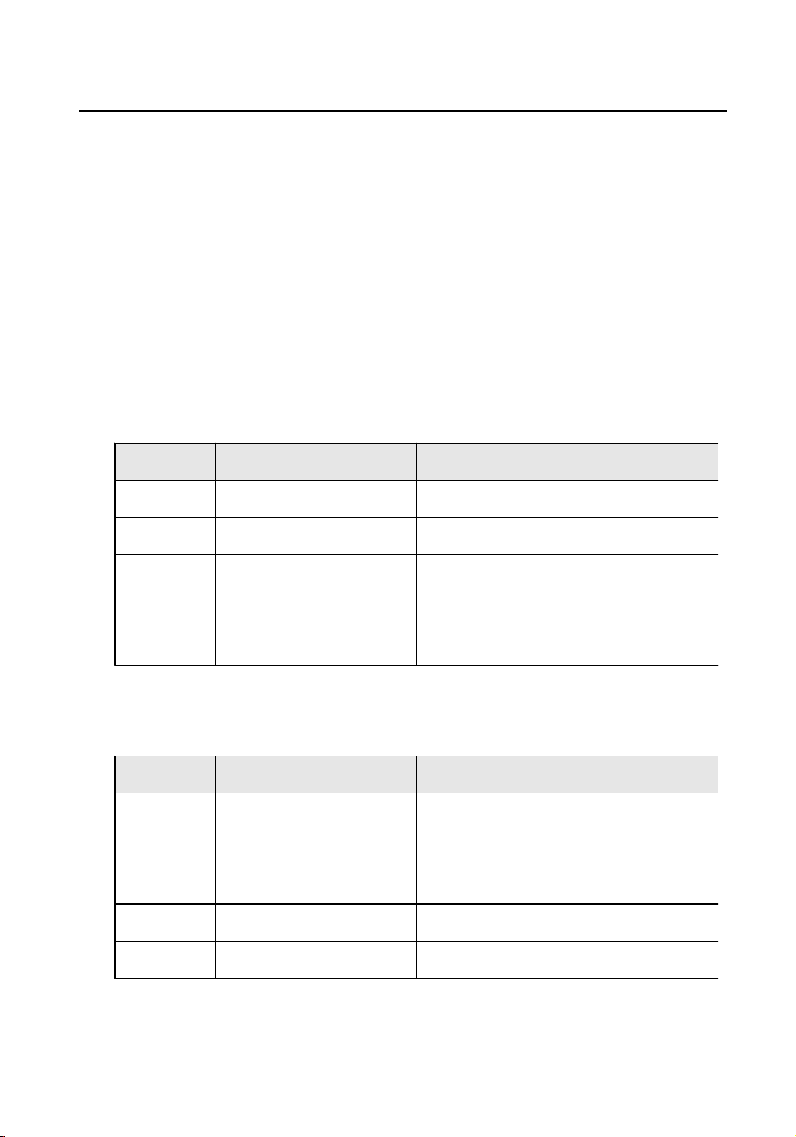
Table 4-1 Number Buon Descripon
No. Descripon No. Descripon
1 1,.?! -*# 6 6mnoMNO
2 2abcABC 7 7pqrsPQRS
3 3defDEF 8 8tuvTUV
4 4ghiGHI 9 9wxyzWXYZ
5 5jklJKL 0 0
Hold 0 to enter special characters.
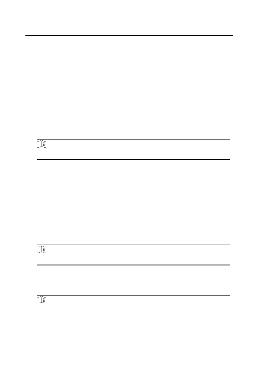
Table 4-2 Number Buon Descripon
No. Descripon No. Descripon
1 1,.#? 6 6_=+
2 2!@% 7 7[];:
3 3^$* 8 8"|<
4 4( )\ 9 9>{}
5 5&/-
Video Intercom Face Recognion Door Staon User Manual
12

Note
●
The password required 8 to 16 characters.
●
The way to enter the password, take buon 2 as an example: Press 2 to enter
the number '2' or hold 2 for 1.5 s and press 2 again to enter the character 'a'.
●
When you have entered the password, press # to switch to conrm the
password.
●
Press * to delete the wrong charater.
3. Press # to acvate.
4.2 Acvate Device via Client Soware
You can only congure and operate the door staon aer creang a password for
the device acvaon.
Default parameters of door staon are as follows:
●
Default IP Address: 192.0.0.65.
●
Default Port No.: 8000.
●
Default User Name: admin.
Steps
1. Run the client soware, click Maintenance and Management → Device
Management → Device to enter the page.
2. Click Online Device.
3. Select an inacvated device and click Acvate.
4. Create a password, and conrm the password.
Note
We highly recommend you to create a strong password of your own choosing
(using a minimum of 8 characters, including at least three kinds of following
categories: upper case leers, lower case leers, numbers, and special characters)
in order to increase the security of your product. And we recommend you reset
your password regularly, especially in the high security system, reseng the
password monthly or weekly can beer protect your product.
5. Click OK to acvate the device.
Video Intercom Face Recognion Door Staon User Manual
13

Note
●
When the device is not acvated, the basic operaon and remote operaon of
device cannot be performed.
●
You can hold the Ctrl or Shi key to select mulple devices in the online
devices, and click the Acvate buon to acvate devices in batch.
Video Intercom Face Recognion Door Staon User Manual
14
5 Local Operaon
5.1 Local Conguraon
5.1.1 Network Sengs
Set the network parameters of the door staon and linked devices.
Steps
1. Long tap on the inial page for 3 s and slide to the le/right and log in the
backend.
Note
By default, the admin password is acvaon password.
2. Tap Network Sengs.
3. Edit IP address, Subnet Mask, Gateway, SIP IP, Main Staon IP and Center IP
according to your needs.
4. Tap < on the top le of the page to save the sengs.
5.1.2 Informaon Sengs
Steps
1. Long tap on the inial page for 3 s and slide to the le/right and log in the
backend.
Note
By default, the admin password is acvaon password.
2. Tap Local Sengs.
3. Congure the parameters according to your needs.
4. Tap < to save the sengs.
Note
●
The No. of the main door staon is 0.
●
The No. of the sub door staons should be set from 1 to 99.
Video Intercom Face Recognion Door Staon User Manual
15
●
Every unit should have at least one main door staon.
●
Up to 8 sub door staon can be linked to the same main door staon.
5.1.3 Add Residents
User Management
Steps
1. Long tap on the inial page for 3 s and slide to the le/right and log in the
backend.
Note
By default, the admin password is acvaon password.
2. Tap User Management.
3. Swipe the main card or enter the password to login.
Note
Create a password to login for the rst me.
Add Users
Steps
1. Tap add buon to enter the sengs page.
2. Set the Room No. for the device.
Note
●
Room No. = Floor No. + No.
●
The oor No. can be omied.
3. Add cards.
1) Tap Card.
2) Tap + to issue card.
3) Set the card No. and swiping the card.
4. Add faces.
1) Tap Face.
2) Face at the camera and tap Capture.
Video Intercom Face Recognion Door Staon User Manual
16
3) Tap Save.
Note
●
You can tap Retry to capture the face again.
●
Up to 3000 faces can be added to the device.
●
Every users can add only one face picture.
5. Add ngerprints.
1) Tap Fingerprint.
2) Tap + to add ngerprint.
3) Put your nger on the ngerprint recognion area.
Note
Up to 3000 users can be added. Every user can add up to 10 ngerprints. Up to
5000 ngerprints can be added.
6. Tap √ to save the sengs.
5.1.4 Recognion Parameters Sengs
Steps
1. Long tap on the inial page for 3 s and slide to the le/right and log in the
backend.
Note
By default, the admin password is acvaon password.
2. Tap Recognion Parameters.
3. Congure the parameters according to your needs.
4. Tap < to save the sengs.
5.1.5 Change Password
Steps
1. Long tap on the inial page for 3 s and slide to the le/right and log in the
backend.
Note
By default, the admin password is acvaon password.
Video Intercom Face Recognion Door Staon User Manual
17

2. Tap Change Password.
3. Select Admin Password, User Password or Public Password from the list.
Admin Password
You can congure parameters (such as network parameters, device
management, device upgrading, etc.) by entering the admin password on the
device rst.
User Password
You can add, delete or modify the informaons of the users by entering the
user password.
Public Password
You can unlock the door by entering public password.
4. Modify the password and tap √ to save the sengs.
5.1.6 Volume Adjustment
Steps
1. Long tap on the inial page for 3 s and slide to the le/right and log in the
backend.
Note
By default, the admin password is acvaon password.
2. Tap Volume Sengs.
3. Adjust loudspeaker and microphone volume.
4. Tap < to save the sengs.
5.1.7 Search Version
Steps
1. Long tap on the inial page for 3 s and slide to the le/right and log in the
backend.
Note
By default, the admin password is acvaon password.
2. Tap About.
3. The device model and system version display on the page.
4. Oponal: Scan the QR code to add the device via mobile client.
Video Intercom Face Recognion Door Staon User Manual
18

5.2 Video Intercom Operaon
5.2.1 Call Resident
Call Resident from Main/Sub Door Staon
Tap Call/Open to enter the calling page.
Enter the room No. and press call buon.
Call Resident from Outer Door Staon
Tap Call/Open to enter the calling page.
Enter 【Community No. + # + Building No. + # + Unit No. + # + Room No.】
and press call buon.
5.2.2 Call Center
Tap Call/Open to enter the calling page.
On the page, tap Center to start calling.
5.3 Unlock Door
5.3.1 Unlock by Password
Unlock by Password
Tap Call/Open to enter the calling page.
Enter 【 # + Room No. + Password + #】, and tap unlock buon.
Video Intercom Face Recognion Door Staon User Manual
19
Unlock by Public Password
Note
Make sure you have created the public password via iVMS-4200 Client
Soware remotely.
Tap Call/Open to enter the calling page.
Enter 【# + Public Password + #】, and tap unlock buon.
5.3.2 Unlock by Presenng Card
Note
Make sure you have issued the card to the device. Refers to User Management for
details.
Present the card on the card reading area to unlock.
5.3.3 Unlock by Fingerprint
Note
●
Make sure you have added the ngerprint to the device.
●
Fingerprint funcon may vary with dierent modules. Please refer to the actual
devices.
Put your nger on the nger recognion module to unlock.
5.3.4 Unlock by Face
Note
Make sure you have added your face picture to the device. Refers to the User
Management for details.
Face forward at the camera to unlock.
Video Intercom Face Recognion Door Staon User Manual
20

6 Conguraon via Client Soware
6.1 Edit Network Parameters
To operate and congure the device via LAN (Local Area Network), you need connect
the device in the same subnet with your PC. You can edit network parameters via
iVMS-4200 client soware.
Steps
1. Select an online acvated device and click the Modify Nenfo.
2. Edit the device IP address and gateway address to the same subnet with your
computer.
3. Enter the password and click OK to save the network parameters modicaon.
Note
●
The default port No. is 8000.
●
The default IP address of the door staon is 192.0.0.65.
●
Aer eding the network parameters of device, you should add the devices to
the device list again.
6.2 Add Device
You should add device to the soware so as to congure the device remotely.
6.2.1 Add Online Device
Before You Start
Make sure the device to be added is in the same subnet with your computer.
Otherwise, please edit network parameters rst.
Steps
1. Click Online Device to select an acve online device.
2. Click Add.
3. Enter corresponding informaon, and click Add.
Video Intercom Face Recognion Door Staon User Manual
21

Figure 6-1 Add to the Client
6.2.2 Add Device by IP Address
Steps
1. Click +Add to pop up the adding devices dialog box.
2. Select IP/Domain as Adding Mode.
3. Enter corresponding informaon.
4. Click Add.
6.2.3 Add Device by IP Segment
Video Intercom Face Recognion Door Staon User Manual
22
You can add many devices at once whose IP addresses are among the IP segment.
Steps
1. Click +Add to pop up the dialog box.
2. Select IP Segment as Adding Mode.
3. Enter corresponding informaon, and click Add.
6.3 Remote Conguraon
Select the device, click
to congure the parameters remotely.
6.3.1 System
Click System on the remote conguraon page to display the device informaon:
Device Informaon, General, Time, System Maintenance, User, and RS-485.
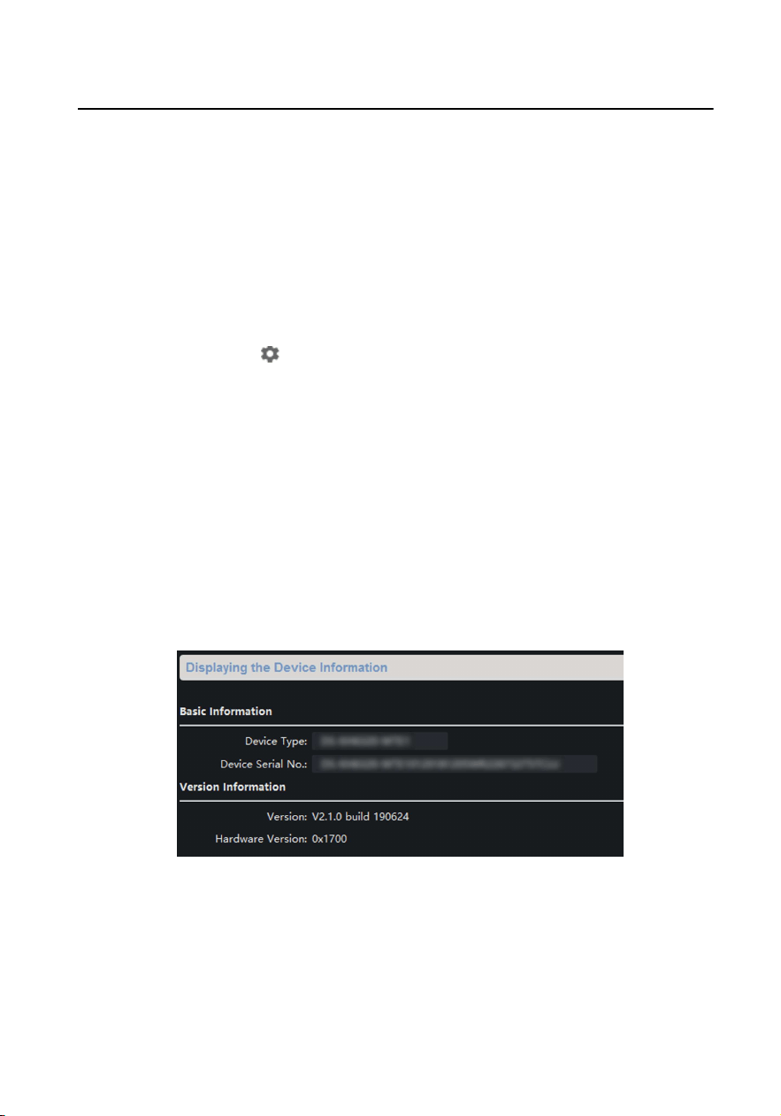
Device Informaon
Click Device Informaon to enter device basic informaon page. You can
view basic informaon (the device type, and serial No.), and version
informaon of the device.
Figure 6-2 Device Informaon
General
Click General to enter device general parameters sengs page. You can
view and edit the device name and device ID.
Video Intercom Face Recognion Door Staon User Manual
23
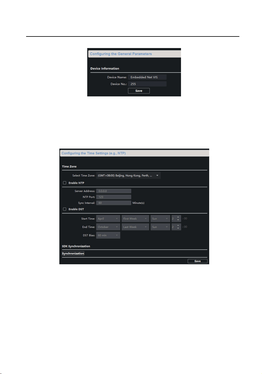
Figure 6-3 General
Time
Click Time to enter the device me sengs page.
Figure 6-4 Synchronize Time
Select Time Zone or Enable NTP. Click Save to save the me sengs.
●
Time Zone
○
Select a me zone from the drop-down list menu.
○
Click Synchronizaon.
●
NTP
Video Intercom Face Recognion Door Staon User Manual
24
○
Check the checkbox of Enable NTP to enable NTP.
○
Enter the server address, NTP port, and synchronizaon interval.
●
DST
○
Check the checkbox of Enable DST to enable DST.
○
Enter the start me and end me of DST, and set the DST bias.
Note
The default port No. is 123.
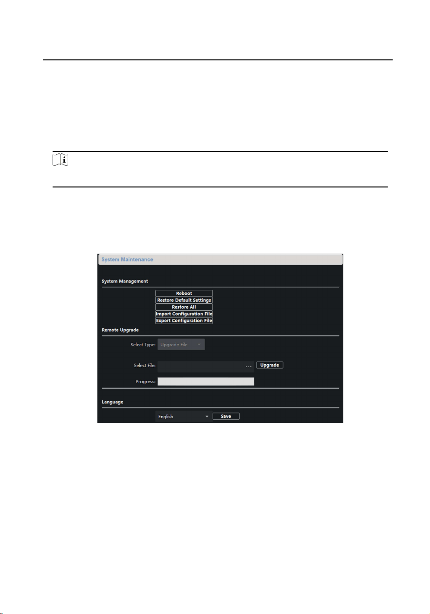
System Maintenance
Click System Maintenance to enter the page.
Figure 6-5 System Maintenance
●
Click Reboot and the system reboot dialog box pops up. Click Yes to
reboot the system.
●
Click Restore Default Sengs to restore the default parameters.
●
Click Restore All to restore all parameters of device and reset the device
to inacve status.
Video Intercom Face Recognion Door Staon User Manual
25

Note
○
Click Restore Default Sengs, all default sengs, excluding network
parameters, will be restored.
○
Click Restore All, all default sengs, including network parameters,
will be restored. The device will be reset to inacvated status.
●
Click Import Conguraon File and the import le window pops up.
Select the path of remote conguraon les. Click Open to import the
remote conguraon le. The conguraon le is imported and the
device will reboot automacally.
●
Click Export Conguraon File and the export le window pops up. Select
the saving path of remote conguraon les and click Save to export the
conguraon le.
●
Click ... to select the upgrade le and click Upgrade to remote upgrade
the device. The process of remote upgrade will be displayed in the
process bar.
●
Select a language, and click Save to change the device system language.
Note
●
The device supports 11 languages: English, Russian, German, Italian,
French, Portuguese, Spanish, Turkish, Arabic, Polish, and Vietnamese.
●
Reboong the device is required aer you change the system language.
User
Click User to enter the user informaon eding page.
Select the user to edit and click Modify to enter the user parameter page.
Video Intercom Face Recognion Door Staon User Manual
26
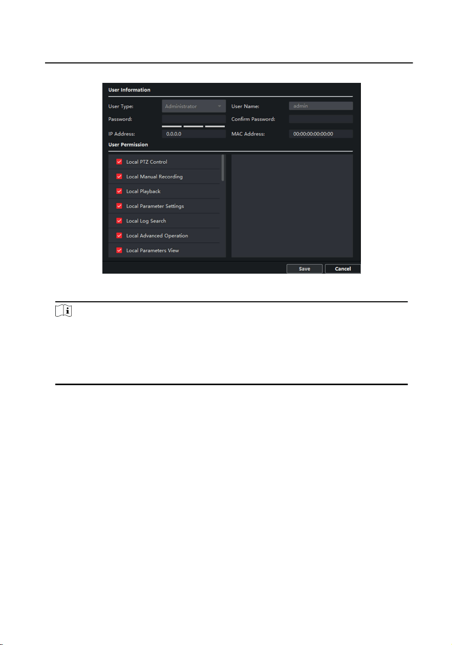
Figure 6-6 User Page
Note
●
The new password and conrm password should be idencal.
●
Aer eding the password of device, click refresh buon from the device
list, the added device will not be there. You should add the device again
with new password to operate the remote conguraon.
RS-485
Click RS485 to enter the RS-485 sengs page. You can view and edit the
RS-485 parameters of the device.
Video Intercom Face Recognion Door Staon User Manual
27
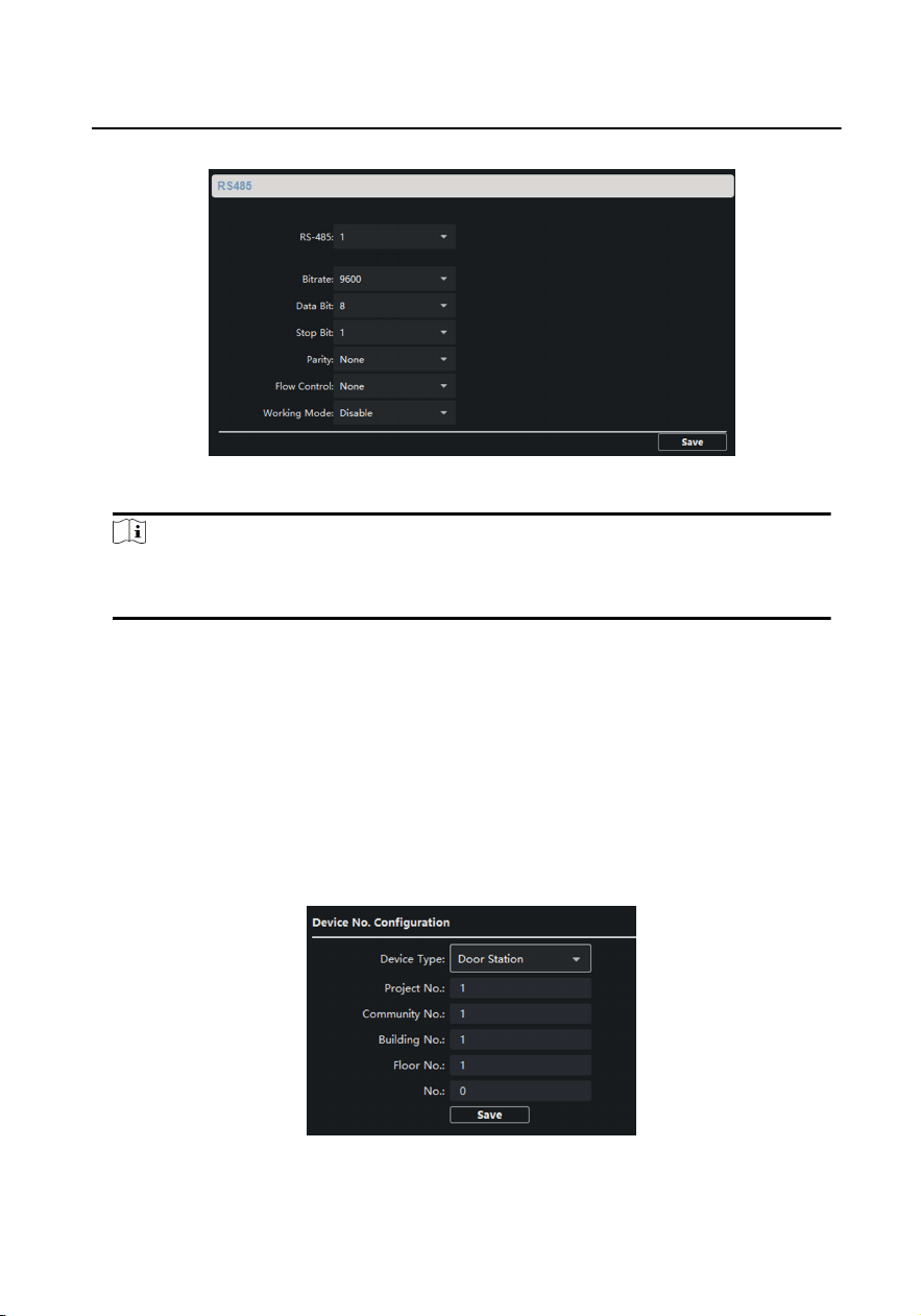
Figure 6-7 RS-485 Sengs
Note
For indoor staon and main staon, there are 3 choices for the working
mode: transparent channel, disable, and custom.
6.3.2 Video Intercom
Click Video Intercom to enter the Video Intercom Sengs page.
Device ID Conguraon
Steps
1. Click ID Conguraon to enter the device ID conguraon page.
Figure 6-8 Device No. Conguraon
Video Intercom Face Recognion Door Staon User Manual
28
2. Select the device type from the drop-down list, and set the corresponding
informaon.
Note
The device type select Door Staon as default. You can select Outer Door Staon
to change the device type.
3. Click Save to enable the device number conguraon.
Note
●
For main door staon, the serial No. is 0.
●
For sub door staon, the serial No. is higher than 0. Serial No. ranges from 1 to
99.
●
For each villa or building, at least one main door staon should be congured,
and sub door staons can be customized.
●
For one main door staon, at most 8 sub door staons can be customized.
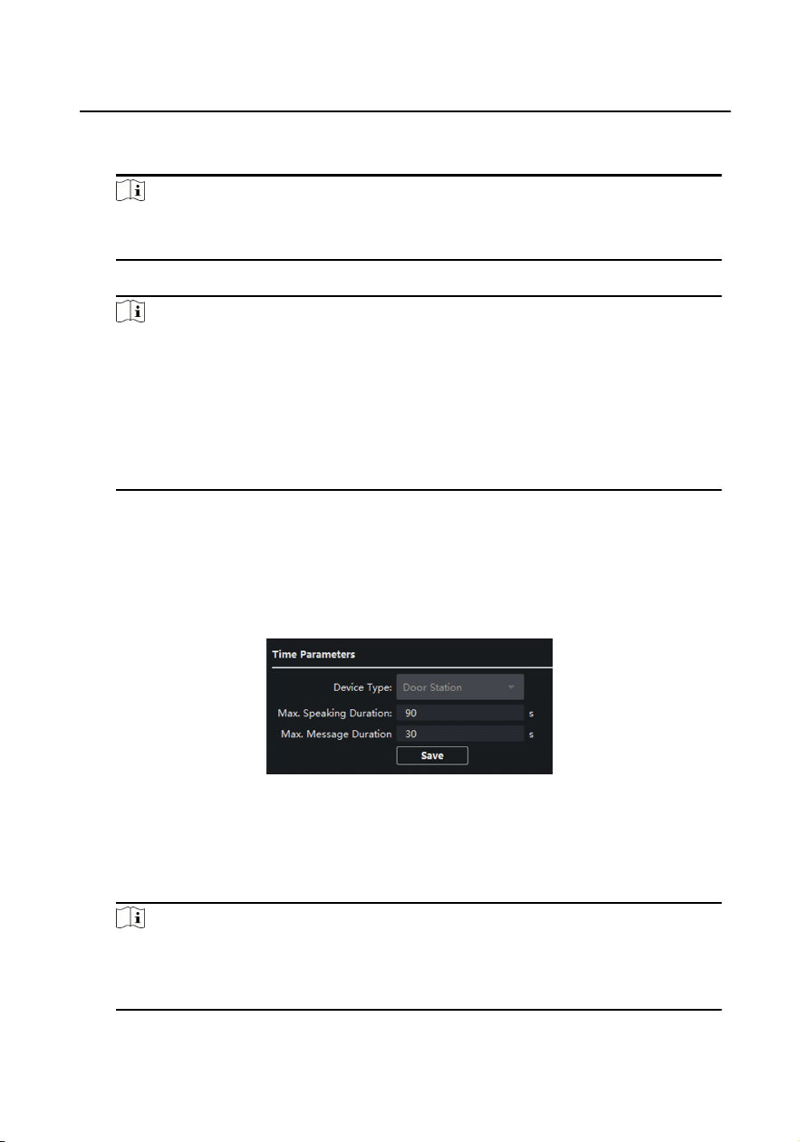
Time Parameters
Steps
1. Click Time Parameters to enter me parameters sengs page.
Figure 6-9 Time Parameters
2. Congure the maximum ring duraon, maximum live view me, and call
forwarding me.
3. Click Save.
Note
For door staon, maximum speaking me and maximum message me should be
congured. Maximum speaking me varies from 90 s to 120 s, and maximum
message me varies from 30 s to 60 s.
Video Intercom Face Recognion Door Staon User Manual
29

Permission Password
Steps
1. Click Permission Password to enter the sengs page.
2. Select Type of the password.
3. Edit the password.
4. Click Save to enable the sengs.
Access Control and Elevator
Before You Start
●
Make sure your door staon is in the mode of main door staon. Only the main
door staon support elevator control funcon.
●
Connecon between the door staon and the elevator controller supports
network interface.
Steps
1. Click Access Control and Elevator to enter corresponding conguraon page.
Video Intercom Face Recognion Door Staon User Manual
30
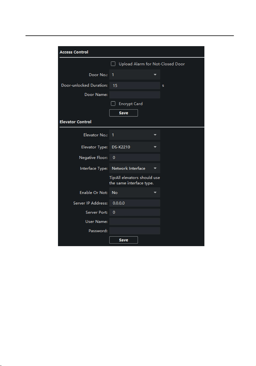
Figure 6-10 Access Control and Elevator
2. Set the Access Control parameters.
1) Select the door No.
2) Set the Door-unlocked Duraon.
3) Oponal: Enable Upload Alarm for Not-Closed Door.
4) Click Save to enable the sengs.
Video Intercom Face Recognion Door Staon User Manual
31
Note
●
The door-unlocked duraon ranges from 1 s to 255 s.
●
If you check Upload Alarm for Not-Closed Door, an alarm will be triggered
automacally if the door is not locked in the congured duraon.
●
Enabling Card Encrypt, the door staon can recognize the encrypted
informaon of the card when you swiping the card on the door staon.
3. Set the Elevator Control parameters.
1) Select an elevator No., and select an elevator controller type for the elevator.
2) Set the negave oor.
3) Select network interface as interface type. Enter the elevator controller's IP
address, port No., user name, and password.
4) Enable the elevator control.
Note
●
Up to 4 elevator controllers can be connected to one door staon.
●
Up to 10 negave oors can be added.
●
Make sure the interface types of elevator controllers, which are connected to
the same door staon, are consistent.
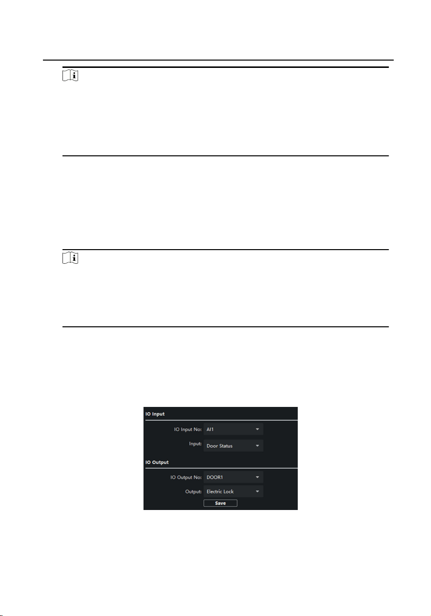
I/O Input and Output
Steps
1. Click I/O Input and Output to enter the I/O input and output sengs page.
Figure 6-11 I/O Input and Output
2. Select I/O input No., input mode, output No., and output mode.
3. Click Save to enable the sengs.
Video Intercom Face Recognion Door Staon User Manual
32

Note
●
For door staon, there are 4 I/O input terminals. By default, Terminal 1 and 2
correspond to Door Status. Terminal 3 and 4 correspond to interfaces of Door
Switch.
●
For door staon, there are 2 I/O Output Terminals. Terminal 1 and 2 correspond
to Door interfaces (NO1/COM/NC1; NO2/COM/NC2) of door staon. Door 1 is
enabled by default. You can enable/disable IO Out according to needs.
Volume Input and Output
Steps
1. Click Volume Input/Output to enter the volume input and output page.
2. Slide the slider to adjust the Volume Input and Volume Output.
3. Click Save to enable the sengs.
Face and Fingerprint Sengs
Steps
1. Click Face and Fingerprint to enter the sengs page.
2. Congure the parameters.
3. Click Save to enable the sengs.
Adversement Sengs
Steps
1. Click Adversement to enter the sengs page.
2. Select the Mode.
3. Click + to add the picture.
4. Slide to set the duraon.
5. Click Save to enable the sengs.
Video Intercom Face Recognion Door Staon User Manual
33
Note
●
Up to 5 pictures can be added. Picture formats requires JPG. The size of the
pictures should be less than 1MB. The switching duraon of the picture ranges
from 1 to 10 seconds. Refers to the Appendix C for the details.
●
When the device has no ads, the default picture displayed on the main page.
6.3.3 Network Sengs
Click Network to enter the Network Sengs page.
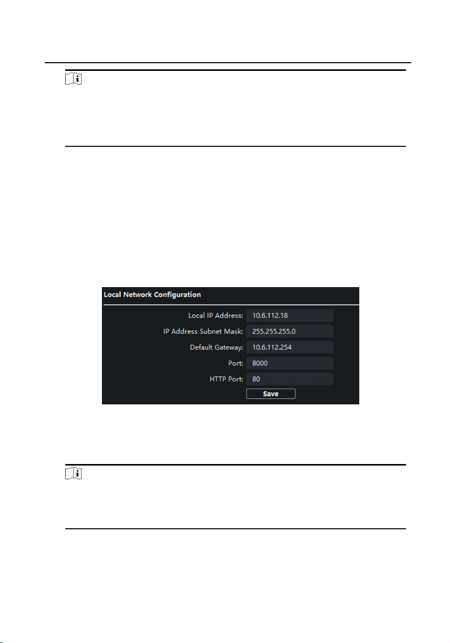
Local Network Conguraon
Steps
1. Click Local Network Conguraon to enter local network conguraon page.
Figure 6-12 Local Network Conguraon
2. Enter the Local IP Address, Subnet Mask, Default Gateway, Port and HTTP Port.
3. Click Save to enable the sengs.
Note
●
The default port No. is 8000.
●
Aer eding the local network parameters of device, you should add the
devices to the device list again.
Linked Device Network Conguraon
Video Intercom Face Recognion Door Staon User Manual
34

Before You Start
On the linked devices network conguraon page, you can congure the network
parameters of main staons, SIP servers and management centers of the same LAN.
The devices can be linked to the door staon and realize the linkage between these
devices.
Steps
1. Click Linked Network Conguraon to enter linked network conguraon page.
2. Enter the main Staon IP Adderss, (Main) Door Staon IP Address, SIP Server IP
Address, Security Control Panel IP Address and Port No.
3. Select the main door staon type from the drop-down list.
4. Click Save to enbale the sengs.
Note
●
Aer adding main staon IP Address, the linkage between indoor staon and
main staon can be realized.
●
Aer adding the door staon IP Address, the video intercom between indoor
staons of same building can be realized.
●
Aer adding SIP Server Address IP, the video intercom of same community:
video intercom between indoor staons of dierent building, calling indoor
staon from outer door staon and video intercom between management
center and indoors.
●
Aer adding management center IP Address, the events can be uploaded to the
management center.
●
For indoor extension, only parameter about the main indoor staon should be
congured.
FTP
Aer conguring the FTP parameters, the captured pictures of door staon will be
uploaded to the FTP server automacally.
Steps
1. Click FTP to enter the FTP parameters sengs page.
Video Intercom Face Recognion Door Staon User Manual
35
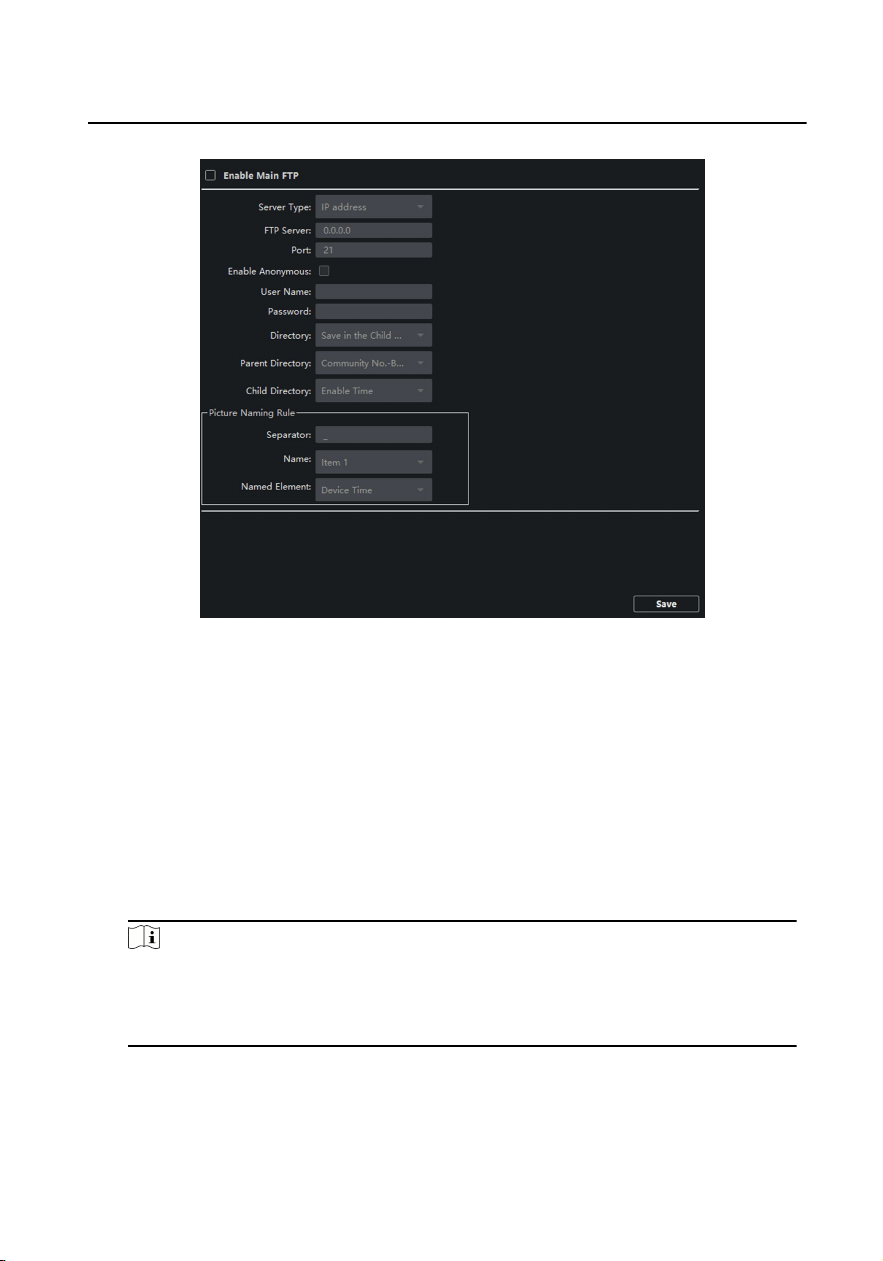
Figure 6-13 FTP Sengs
2. Enable Enable Main FTP.
3. Select IP address from the drop-down list of server mode.
4. Enter the FTP server address, and port No.
5. Oponal: Enable the anonymity.
6. Enter the name and password.
7. Select the directory structure and set the separator, naming item, and naming
element.
8. Click Save to enable the sengs.
Note
●
The default port No. is 21.
●
To enable anonymity or not is according to whether the FTP server enables
anonymity.
Advanced Sengs
Video Intercom Face Recognion Door Staon User Manual
36

Steps
1. Click Advanced Sengs to enter the advanced network sengs page.
Figure 6-14 Advanced Sengs
2. Enter the DNS server addresses.
3. Click Save to enable the sengs.
6.3.4 Video Display Sengs
Click Video Display to enter the Video Display Sengs page.
Video Parameters
Steps
1. Click Video Parameters to enter the video parameters sengs page.
Video Intercom Face Recognion Door Staon User Manual
37
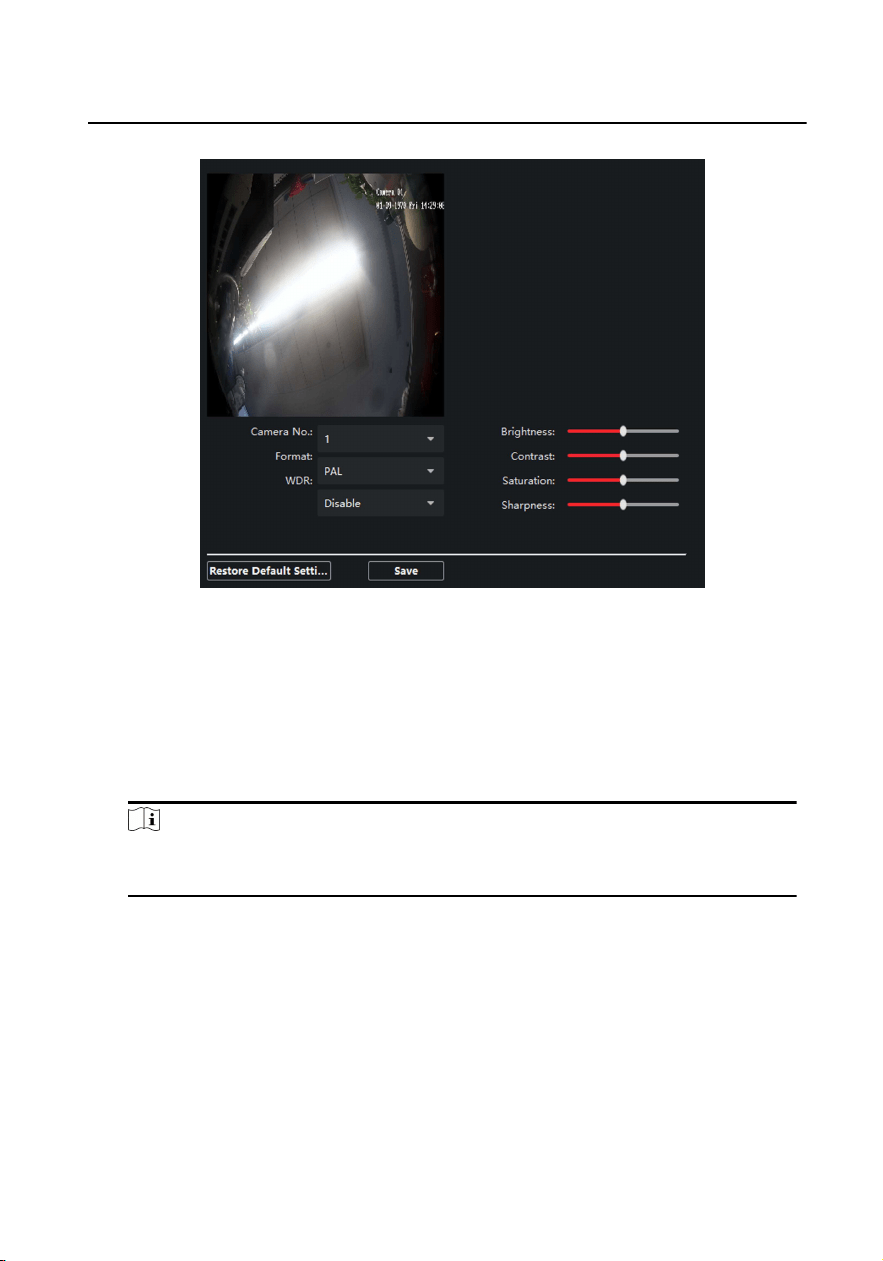
Figure 6-15 Video Parameters
2. Select the Camera No.
3. Select the video standard (PAL and NTSC can be selected).
4. Oponal: Enable WDR mode.
5. Set the Brightness, Contrast, Saturaon and Sharpness of the video.
6. Click Save.
Note
Click Restore Default Sengs to restore all video parameters excluding network
parameters to the factory sengs.
Video & Audio
Steps
1. Click Video & Audio to enter the video parameters sengs page.
Video Intercom Face Recognion Door Staon User Manual
38
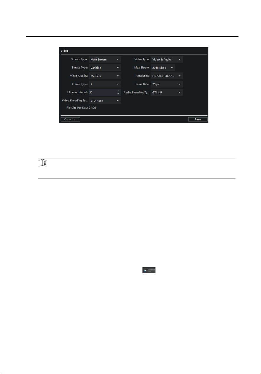
Figure 6-16 Video & Audio
2. Set the parameters.
3. Click Save.
Note
It's suggested to keep the default sengs to ensure the video/image quality.
6.4 Device Management
Device management includes device acvaon, adding device, eding device, and
deleng device, and so on.
Aer running the iVMS-4200, video intercom devices should be added to the client
soware for remote conguraon and management.
6.5 Organizaon Management
On the main page of the Client Soware, click
PersonalManagement to enter
the conguraon page.
6.5.1 Add Organizaon
Steps
1. In the organizaon list on the le, click +Add.
2. Enter the Organizaon Name as desired.
3. Click OK to save the adding.
Video Intercom Face Recognion Door Staon User Manual
39
4. Oponal: You can add mulple levels of organizaons according to the actual
needs.
1) You can add mulple levels of organizaons according to the actual needs.
2) Then the added organizaon will be the sub-organizaon of the upper-level
organizaon.
Note
Up to 10 levels of organizaons can be created.
6.5.2 Modify and Delete Organizaon
You can select the added organizaon and click
to modify its name.
You can select an organizaon, and click X buon to delete it.
Note
●
The lower-level organizaons will be deleted as well if you delete an organizaon.
●
Make sure there is no person added under the organizaon, or the organizaon
cannot be deleted.
6.6 Person Management
Aer adding the organizaon, you can add person to the organizaon and manage
the added person such as issuing cards in batch, imporng and exporng person's
informaon in batch, etc.
Note
●
Up to 2,000 persons can be added.
●
Up to 5 cards can be added to each person.
6.6.1 Add Person
Person informaon is necessary for the video intercom system. And when you set
linked device for the person, the intercom between intercom devices can be realized.
Steps
1. Select an organizaon in the organizaon list and click Add on the Person panel to
pop up the adding person dialog.
Video Intercom Face Recognion Door Staon User Manual
40
Note
The Person No. will be generated automacally and is editable.
2. Set basic person informaon.
1) Enter basic informaon: name, tel, birthday details, eecve period and email
address.
Note
The length of person name should be less than 15 characters.
2) Click Add face to upload the photo.
Note
The picture should be in *.jpg format.
Click Upload Select the person picture from the local PC to upload it
to the client.
Click Take Phone Take the person's photo with the PC camera.
Click Remote
Collecon
Take the person's photo with the collecon device.
3. Issue the card for the person.
1) Click Credenal → Card .
2) Click + to pop up the Add Card dialog.
3) Select Normal Card as Card Type.
4) Enter the Card No.
5) Click Read and the card(s) will be issued to the person.
4. Link the device to the person.
1) Set the linked devices.
Linked Device
You can bind the indoor staon to the person.
Note
If you select Analog Indoor Staon in the Linked Device, the Door Staon
eld will display and you are required to select the door staon to
communicate with the analog indoor staon.
Room No.
You can enter the room No. of the person.
Video Intercom Face Recognion Door Staon User Manual
41

2) Click OK to save the sengs.
5. Click Add to save the sengs.
6.6.2 Modify and Delete Person
Select the person and click Edit to open the eding person dialog.
To delete the person, select a person and click Delete to delete it.
Note
If a card is issued to the current person, the linkage will be invalid aer the person is
deleted.
6.6.3 Import and Export Person Informaon
The person informaon can be imported and exported in batch.
Steps
1. Exporng Person: You can export the added persons' informaon in Excel format
to the local PC.
1) Aer adding the person, you can click Export Person to pop up the following
dialog.
2) Click ... to select the path of saving the exported Excel le.
3) Check the checkboxes to select the person informaon to export.
4) Click OK to start exporng.
2. Imporng Person: You can import the Excel le with persons informaon in batch
from the local PC.
1) Click Import Person.
2) You can click Download Template for Imporng Person to download the
template rst.
3) Input the person informaon to the downloaded template.
4) Click ... to select the Excel le with person informaon.
5) Click OK to start imporng.
6.6.4 Get Person Informaon from Device
Video Intercom Face Recognion Door Staon User Manual
42

If the added device has been congured with person informaon (including person
details, ngerprint, issued card informaon), you can get the person informaon
from the device and import to the client for further operaon.
Steps
Note
This funcon is only supported by the device the connecon mothod of which is
TCP/IP when adding the device.
1. In the organizaon list on the le, click to select an organizaon to import the
persons.
2. Click Get from Device to pop up the dialog box.
3. The added device will be displayed.
4. Click to select the device and then click Get to start geng the person informaon
from the device.
Note
●
The person informaon, including person details, person's ngerprint
informaon (if congured), and the linked card (if congured), will be imported
to the selected organizaon.
●
If the person name stored in the device is empty, the person name will be lled
with the issued card No. aer imporng to the client.
6.6.5 Change Person to Other Organizaon
You can move the person to another organizaon if needed.
Steps
1. Select the person in the list and click Change Organizaon.
2. Select the organizaon to move the person to.
3. Click OK to save the sengs.
6.6.6 Add Person in Batch
Enter a short descripon of your task here (oponal).
Before You Start
Enter the prerequisites here (oponal).
Enter the context of your task here (oponal).
Video Intercom Face Recognion Door Staon User Manual
43
Steps
1. Enter your rst step here.
Enter the result of your step here (oponal).
Example
Enter an example that illustrates the current task (oponal).
What to do next
Enter the tasks the user should do aer nishing this task (oponal).
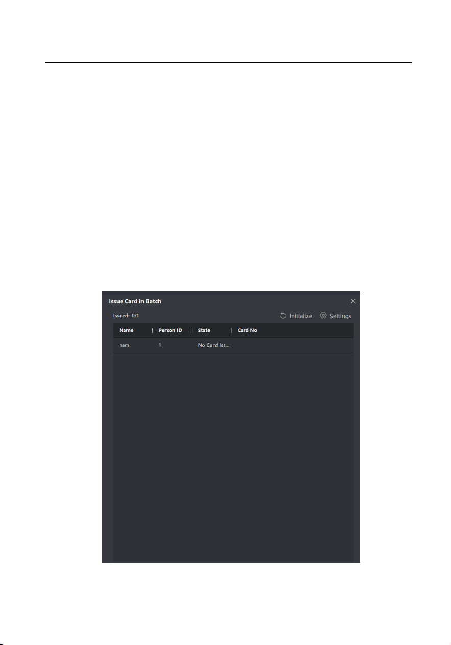
6.6.7 Issue Card in Batch
You can issue mulple cards for the person with no card issued in batch.
Steps
1. Click Batch Issue Cards to enter the dialog page. All the added person with no card
issued will display in the Person(s) with No Card Issued list.
Figure 6-17 Issue Card in Batch
Video Intercom Face Recognion Door Staon User Manual
44
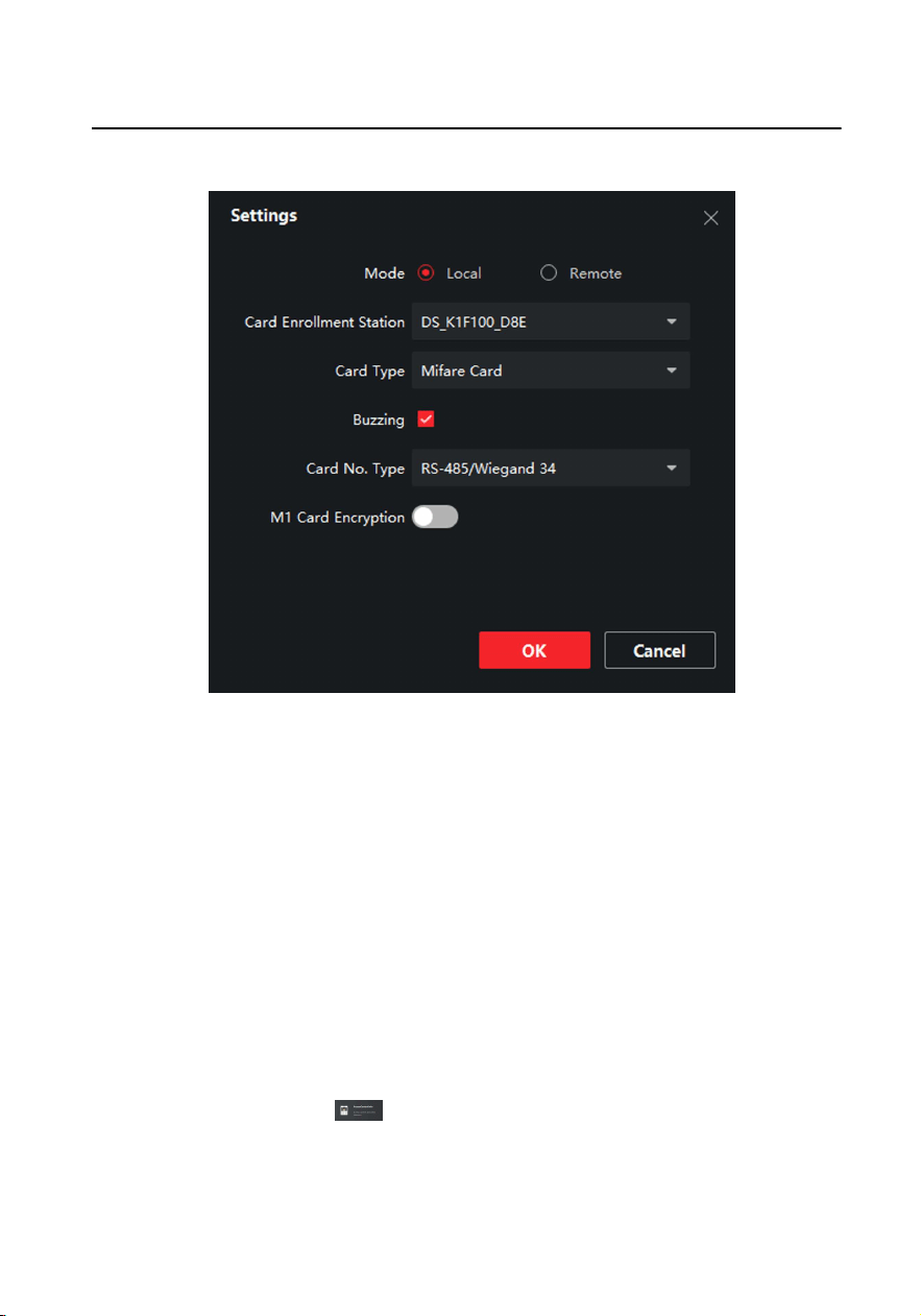
2. Click Sengs.
Figure 6-18 Card Sengs
3. Select Card Type and Card No. Type.
4. Click OK to save the sengs.
Result
Aer issuing the card to the person, the person and card informaon will display in
the Person(s) with Card Issued list.
6.6.8 Permission Sengs
Add Permissions
Steps
1.
On the main page, click
AccessControlInfo → Access Group to enter the
page.
2. Click +Add to pop up the adding dialog box.
Video Intercom Face Recognion Door Staon User Manual
45

3. Congure the parameters.
1) Enter the Name of the permission.
2) Select the Template of the schedule.
3) Check the person to Selected according to your needs.
4) Check the device to Selected according to your needs.
4. Click Save.
5. Check the permission and click Apply All to Device.
The status of the permission displays as Applied.
6. Oponal: Click Applying Status to check the details.
Modify/Delete Permissions
On the page of the permission sengs, click
to edit the parameters of the
permission.
Select one or more permissions, click Delete to remove the permissions.
6.7 Video Intercom Sengs
The Video Intercom Management module provides the funcon of video intercom,
checking call logs and managing noce via the iVMS-4200 Client Soware.
Note
For the user with access control module permissions, the user can enter the Access
Control module and manage video intercom and search informaon.
You should add the device to the soware and congure the person to link the
device in Access Control module before your conguraon remotely.
On the main page, click
AccessControlInfo → Video Intercom → Video
Intercom on the le bar to enter the Video Intercom page.
6.7.1 Receive Call from Door Staon
Steps
1. Select the client soware in the device page to start calling the iVMS-4200 Client
Soware and an incoming call dialog will pop up in the client soware.
2. Click Answer to answer the call. Or click Hang Up to decline the call.
Video Intercom Face Recognion Door Staon User Manual
46

3. Aer you answer the call, you will enter the In Call window.
●
Click
to adjust the volume of the loudspeaker.
●
Click
to adjust the volume of the microphone.
●
Click Hang Up to hang up the dialog.
●
Click
to open the door remotely.
Note
●
One video intercom device can only connect with one client soware.
●
The maximum ring duraon can be set from 15s to 60s via the Remote
Conguraon of the video intercom device.
●
The maximum speaking duraon between indoor staon and iVMS-4200 can be
set from 120s to 600s via the Remote Conguraon of indoor staon.
●
The maximum speaking duraon between door staon and iVMS-4200 can be
set from 90s to 120s via the Remote Conguraon of door staon.
6.7.2 Live View via Door Staon
Steps
1. On the main page of the client soware, click Main View to enter the Live View
page.
2. In the le list of the window, double-click the device IP or click the play icon to live
view.
3. Oponal: On the Live View page, control-click and select Capture to get the
picture of the live view.
6.7.3 Release Noce
You can create dierent types of noces and send them to the residents. Four noce
types are available, including Adversing, Property, Alarm and Noce Informaon.
Before You Start
Make sure the person has been added to the client.
Steps
1. On the video intercom sengs page, click Noce to enter the page.
2. Click +Add to pop up the adding dialog box.
3. Select the person according to your needs.
Video Intercom Face Recognion Door Staon User Manual
47
4. Edit the Subject, Type and Informaon.
5. Click View to select the picture.
6. Click Send.
Note
●
Up to 63 characters are allowed in the Subject eld.
●
Up to 6 pictures in the JPGE format can be added to one noce. And the
maximum size of one picture is 512KB.
●
Up to 1023 characters are allowed in the Informaon eld.
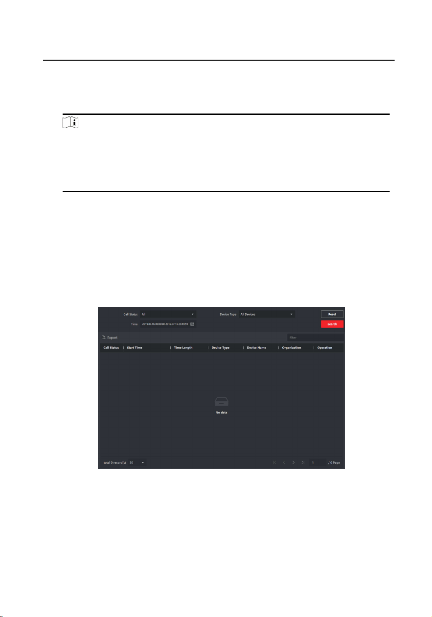
6.7.4 Search Video Intercom Informaon
Search Call Logs
Steps
1. On the Video Intercom page, click Call Log to enter the page.
Figure 6-19 Search Call Logs
2. Set the search condions, including call status, device type, start me and end
me.
Call Status
Click ˅ to unfold the drop-down list and select the call status as Dialed,
Received or Missed. Or select All to search logs with all statuses.
Video Intercom Face Recognion Door Staon User Manual
48

Device Type
Click ˅ to unfold the drop-down list and select the device type as Indoor
Staon, Door Staon, Outer Door Staon or Analog Indoor Staon. Or select
All Devices to search logs with all device types.
Start Time/End Time
Click the me icon to specify the start me and end me of a me period to
search the logs.
Reset the Sengs Click Reset to reset all the congured search condions.
3. Click Search and all the matched call logs will display on this page.
4. Oponal: Check the detailed informaon of searched call logs, such as call status,
ring/speaking duraon, device name, resident organizaon, etc.
5. Oponal: Input keywords in the Search eld to lter the desired log.
6. Oponal: Click Export to export the call logs to your PC.
Search Noce
Steps
1. On the Video Intercom page, click Noce to enter the page.
2. Set the search condions, including noce type, start me and end me.
Type
Select Adversing Informaon, Property Informaon, Alarm Informaon or
Noce Informaon as Type according to your needs.
Start Time/End Time
Click the me icon to specify the start me and end me of a me period to
search the logs.
Reset the Sengs Click Reset to reset all the congured search condiions.
3. Click Search and the matched noce will display on this page.
4. Oponal: Click Export to export the noces to your PC.
Video Intercom Face Recognion Door Staon User Manual
49

UD16891B